

69-2041 - R182J, R482J, YHR845A,R847A ... - PexSupply.com
69-2041 - R182J, R482J, YHR845A,R847A ... - PexSupply.com
69-2041 - R182J, R482J, YHR845A,R847A ... - PexSupply.com

Create successful ePaper yourself
Turn your PDF publications into a flip-book with our unique Google optimized e-Paper software.
<strong>R182J</strong>, <strong>R482J</strong>, <strong>YHR845A</strong>,<strong>R847A</strong>, RA89A, RA832A SWITCHING RELAYS<br />
INSTALLATION<br />
When Installing this Product<br />
1. Read these instructions carefully. Failure to follow<br />
instructions can damage product or cause a hazardous<br />
condition.<br />
2. Check the ratings given in the instructions and on<br />
the product to make sure the product is suitable for<br />
your application.<br />
3. Make sure installer is a trained, experienced service<br />
technician.<br />
4. After <strong>com</strong>pleting installation, use these instructions<br />
to check out product operation.<br />
WARNING<br />
Electrocution Hazard.<br />
Can cause property damage, severe injury, or<br />
death.<br />
Transformer core not bonded.<br />
Disconnect power supply before wiring to prevent<br />
electrical shock or equipment damage.<br />
Mounting<br />
For replacement, mount the relay in the same location as<br />
the old relay. If this is a new installation, locate the relay<br />
vertically on a solid wall or partition as close as possible to<br />
the device to be controlled. Select a location that is easily<br />
accessible for installation and service.<br />
NOTE:<br />
To reduce the possible transformer hum and<br />
relay noise that is sometimes amplified by<br />
mounting surfaces such as sheet metal, plasterboard,<br />
and similar materials, place rubber or felt<br />
washers between the case and the mounting<br />
surface.<br />
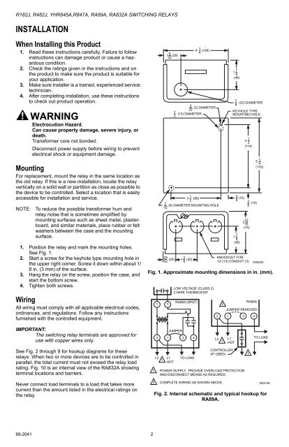
1. Position the relay and mark the mounting holes.<br />
See Fig. 1.<br />
2. Start a screw for the keyhole type mounting hole in<br />
the upper right corner. Screw it down within about 1/<br />
8 in. (3 mm) of the surface.<br />
3. Hang the relay on the screw, position the case, and<br />
start the bottom screw.<br />
4. Tighten both screws.<br />
Wiring<br />
All wiring must <strong>com</strong>ply with all applicable electrical codes,<br />
ordinances, and regulations. Follow any instructions<br />
furnished with the controlled equipment.<br />
5<br />
1 (29)<br />
32<br />
1<br />
3 (89)<br />
2<br />
1<br />
4 (108)<br />
4<br />
3<br />
(2) DIAMETER<br />
32<br />
7<br />
1<br />
8<br />
(48)<br />
7<br />
(22) DIAMETER<br />
8<br />
1<br />
2 (13) DIAMETER KEYHOLE TYPE<br />
MOUNTING HOLE<br />
7<br />
32 (6) DIAMETER MOUNTING HOLE 1<br />
3<br />
8 (10)<br />
7<br />
8<br />
(48)<br />
1<br />
4<br />
2<br />
(114)<br />
25<br />
32 (20) 3<br />
KNOCKOUT FOR<br />
1 (35)<br />
8<br />
1/2 (13) CONDUIT (3)<br />
3<br />
8 (10)<br />
15<br />
2<br />
16<br />
(75)<br />
1<br />
5<br />
4<br />
(133)<br />
M3823B<br />
Fig. 1. Approximate mounting dimensions in in. (mm).<br />
T<br />
T<br />
LOW VOLTAGE (CLASS 2)<br />
2-WIRE THERMOSTAT<br />
RA89A (SPST)<br />
RA89A<br />
2<br />
JUMPER REMOVED<br />
2 1 3 4<br />
IMPORTANT:<br />
The switching relay terminals are approved for<br />
use with copper wires only.<br />
JUMPER<br />
2 1 3 4<br />
L2<br />
1<br />
L1<br />
HOT<br />
TO LOAD<br />
See Fig. 2 through 9 for hookup diagrams for these<br />
relays. When two or more devices are to be controlled in<br />
parallel, the total current must not exceed the relay load<br />
rating. Fig. 10 is an internal view of the RA832A showing<br />
terminal locations and barriers.<br />
Never connect load terminals to a load that takes more<br />
current than the amount listed in the electrical ratings on<br />
the relay.<br />
L2<br />
1<br />
L1<br />
HOT<br />
TO LOAD<br />
CONTROLLER<br />
(IF USED) 1<br />
1 POWER SUPPLY. PROVIDE OVERLOAD PROTECTION<br />
AND DISCONNECT MEANS AS REQUIRED.<br />
2 COMPLETE WIRING AS SHOWN ABOVE.<br />
M3819A<br />
Fig. 2. Internal schematic and typical hookup for<br />
RA89A.<br />
<strong>69</strong>-<strong>2041</strong> 2


