

69-2041 - R182J, R482J, YHR845A,R847A ... - PexSupply.com
69-2041 - R182J, R482J, YHR845A,R847A ... - PexSupply.com
69-2041 - R182J, R482J, YHR845A,R847A ... - PexSupply.com

You also want an ePaper? Increase the reach of your titles
YUMPU automatically turns print PDFs into web optimized ePapers that Google loves.
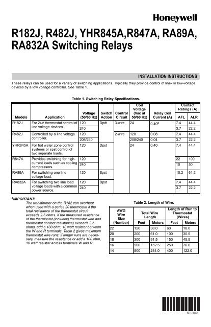
<strong>R182J</strong>, <strong>R482J</strong>, <strong>YHR845A</strong>,<strong>R847A</strong>, RA89A,<br />
RA832A Switching Relays<br />
INSTALLATION INSTRUCTIONS<br />
These relays can be used for a variety of switching applications. Typically they provide control of line- or low-voltage<br />
devices by a low voltage controller. See Table 1.<br />
Models<br />
<strong>R182J</strong><br />
<strong>R482J</strong><br />
<strong>YHR845A</strong><br />
<strong>R847A</strong><br />
RA89A<br />
RA832A<br />
Application<br />
For 24V thermostat control of<br />
line voltage devices.<br />
Controlled by a line voltage<br />
controller.<br />
For hot water zone control<br />
systems or spst control of<br />
two separate loads.<br />
Table 1. Switching Relay Specifications.<br />
Voltage<br />
(50/60 Hz)<br />
Switch<br />
Action<br />
Control<br />
Circuit<br />
Coil<br />
Voltage<br />
(Vac at<br />
50/60 Hz)<br />
Relay Coil<br />
Current (A)<br />
Contact<br />
Ratings (A)<br />
AFL<br />
ALR<br />
120 Dpdt 3-wire 24 a<br />
0.40 7.4 44.4<br />
240 3.7 22.2<br />
120 2-wire 120 0.08 7.4 44.4<br />
208/240 208/240 0.04 3.7 22.2<br />
120 Dpst 24 0.40 7.4 44.4<br />
Provides switching for highcurrent<br />
loads such as cooling<br />
120 22 100<br />
240 10 50<br />
<strong>com</strong>pressors.<br />
For switching one line<br />
voltage load.<br />
For switching two line load<br />
voltage loads with a <strong>com</strong>mon<br />
power source.<br />
120 Spst 10.2 61.2<br />
120 Dpst 7.4 44.4<br />
240 3.7 22.2<br />
a IMPORTANT:<br />
The transformer on the R182 can overheat<br />
when used with a series 20 thermostat if the<br />
total resistance of the thermostat circuit<br />
exceeds 2.5 ohms. If the measured resistance<br />
of the thermostat (including thermostat wire and<br />
thermostat contact resistance) exceeds 2.5<br />
ohms, add a 100 ohm, 10 watt resistor between<br />
the W and R terminals. Table 2 gives maximum<br />
thermostat wire runs; if longer runs are necessary,<br />
measure the resistance or add a 100 ohm,<br />
10 watt resistor across terminals W and R.<br />
AWG<br />
Wire<br />
Size<br />
(Number)<br />
Table 2. Length of Wire.<br />
Total Wire<br />
Length<br />
Length of Run to<br />
Thermostat<br />
(Wires)<br />
Feet Meters Feet Meters<br />
22 120 38.0 60 18.0<br />
20 200 61.0 100 30.5<br />
18 300 91.5 150 45.5<br />
16 500 152.5 250 76.0<br />
14 800 244.0 400 122.0<br />
<strong>69</strong>-<strong>2041</strong>
<strong>R182J</strong>, <strong>R482J</strong>, <strong>YHR845A</strong>,<strong>R847A</strong>, RA89A, RA832A SWITCHING RELAYS<br />
INSTALLATION<br />
When Installing this Product<br />
1. Read these instructions carefully. Failure to follow<br />
instructions can damage product or cause a hazardous<br />
condition.<br />
2. Check the ratings given in the instructions and on<br />
the product to make sure the product is suitable for<br />
your application.<br />
3. Make sure installer is a trained, experienced service<br />
technician.<br />
4. After <strong>com</strong>pleting installation, use these instructions<br />
to check out product operation.<br />
WARNING<br />
Electrocution Hazard.<br />
Can cause property damage, severe injury, or<br />
death.<br />
Transformer core not bonded.<br />
Disconnect power supply before wiring to prevent<br />
electrical shock or equipment damage.<br />
Mounting<br />
For replacement, mount the relay in the same location as<br />
the old relay. If this is a new installation, locate the relay<br />
vertically on a solid wall or partition as close as possible to<br />
the device to be controlled. Select a location that is easily<br />
accessible for installation and service.<br />
NOTE:<br />
To reduce the possible transformer hum and<br />
relay noise that is sometimes amplified by<br />
mounting surfaces such as sheet metal, plasterboard,<br />
and similar materials, place rubber or felt<br />
washers between the case and the mounting<br />
surface.<br />
1. Position the relay and mark the mounting holes.<br />
See Fig. 1.<br />
2. Start a screw for the keyhole type mounting hole in<br />
the upper right corner. Screw it down within about 1/<br />
8 in. (3 mm) of the surface.<br />
3. Hang the relay on the screw, position the case, and<br />
start the bottom screw.<br />
4. Tighten both screws.<br />
Wiring<br />
All wiring must <strong>com</strong>ply with all applicable electrical codes,<br />
ordinances, and regulations. Follow any instructions<br />
furnished with the controlled equipment.<br />
5<br />
1 (29)<br />
32<br />
1<br />
3 (89)<br />
2<br />
1<br />
4 (108)<br />
4<br />
3<br />
(2) DIAMETER<br />
32<br />
7<br />
1<br />
8<br />
(48)<br />
7<br />
(22) DIAMETER<br />
8<br />
1<br />
2 (13) DIAMETER KEYHOLE TYPE<br />
MOUNTING HOLE<br />
7<br />
32 (6) DIAMETER MOUNTING HOLE 1<br />
3<br />
8 (10)<br />
7<br />
8<br />
(48)<br />
1<br />
4<br />
2<br />
(114)<br />
25<br />
32 (20) 3<br />
KNOCKOUT FOR<br />
1 (35)<br />
8<br />
1/2 (13) CONDUIT (3)<br />
3<br />
8 (10)<br />
15<br />
2<br />
16<br />
(75)<br />
1<br />
5<br />
4<br />
(133)<br />
M3823B<br />
Fig. 1. Approximate mounting dimensions in in. (mm).<br />
T<br />
T<br />
LOW VOLTAGE (CLASS 2)<br />
2-WIRE THERMOSTAT<br />
RA89A (SPST)<br />
RA89A<br />
2<br />
JUMPER REMOVED<br />
2 1 3 4<br />
IMPORTANT:<br />
The switching relay terminals are approved for<br />
use with copper wires only.<br />
JUMPER<br />
2 1 3 4<br />
L2<br />
1<br />
L1<br />
HOT<br />
TO LOAD<br />
See Fig. 2 through 9 for hookup diagrams for these<br />
relays. When two or more devices are to be controlled in<br />
parallel, the total current must not exceed the relay load<br />
rating. Fig. 10 is an internal view of the RA832A showing<br />
terminal locations and barriers.<br />
Never connect load terminals to a load that takes more<br />
current than the amount listed in the electrical ratings on<br />
the relay.<br />
L2<br />
1<br />
L1<br />
HOT<br />
TO LOAD<br />
CONTROLLER<br />
(IF USED) 1<br />
1 POWER SUPPLY. PROVIDE OVERLOAD PROTECTION<br />
AND DISCONNECT MEANS AS REQUIRED.<br />
2 COMPLETE WIRING AS SHOWN ABOVE.<br />
M3819A<br />
Fig. 2. Internal schematic and typical hookup for<br />
RA89A.<br />
<strong>69</strong>-<strong>2041</strong> 2
<strong>R182J</strong>, <strong>R482J</strong>, <strong>YHR845A</strong>,<strong>R847A</strong>, RA89A, RA832A SWITCHING RELAYS<br />
LOW VOLTAGE (CLASS 2)<br />
2-WIRE THERMOSTAT<br />
T<br />
T<br />
X<br />
X<br />
AUXILIARY TO LOW<br />
OR MILLIVOLTAGE<br />
(POWERPILE) LOAD<br />
RA832A<br />
<strong>R482J</strong><br />
2 1 3 4<br />
3<br />
3<br />
CONTROLLER<br />
1 2 4 5 3 8 7 6<br />
1<br />
L2<br />
1<br />
L1<br />
HOT<br />
LOAD 1<br />
LOAD 2<br />
(OPTIONAL)<br />
POWER SUPPLY. PROVIDE OVERLOAD PROTECTION<br />
AND DISCONNECT MEANS AS REQUIRED. M3821A<br />
Fig. 3. Internal schematic and typical hookup for<br />
RA832A.<br />
1<br />
2<br />
L1<br />
(HOT)<br />
N.O. N.C. COM. N.O. N.C. COM.<br />
L2 TO LOAD TO LOAD<br />
1<br />
POWER SUPPLY. PROVIDE OVERLOAD PROTECTION<br />
AND DISCONNECT MEANS AS REQUIRED.<br />
<strong>R182J</strong><br />
2<br />
CONTROLLER (IF USED) MUST BE SNAP ACTION OR<br />
MERCURY SWITCH TYPE.<br />
W X R B<br />
3<br />
OHMS<br />
K1<br />
K1<br />
K2<br />
3<br />
N.O. CONTACTS MAKE BEFORE N.C CONTACTS BREAK,<br />
AND N.C. CONTACTS MAKE BEFORE N.O. CONTACTS BREAK.<br />
M8234A<br />
Fig. 6. Internal schematics and typical hookup for<br />
<strong>R482J</strong>.<br />
K1<br />
K2<br />
2<br />
HYDRONIC HEATING<br />
CONTROL TERMINALS<br />
TO ADDITIONAL <strong>YHR845A</strong><br />
RELAYS FOR OTHER ZONES<br />
1<br />
2<br />
L1 L2 4 3 7 6<br />
L1 L2<br />
(HOT)<br />
1<br />
LOAD<br />
LOAD<br />
N.O. N.C. N.O. N.C.<br />
POWER SUPPLY. PROVIDE OVERLOAD PROTECTION AND<br />
DISCONNECT MEANS AS REQUIRED.<br />
N.O. CONTACTS MAKE BEFORE N.C CONTACTS BREAK,<br />
AND N.C. CONTACTS MAKE BEFORE N.O. CONTACTS BREAK.<br />
M8232A<br />
Fig. 4. Internal schematic and typical hookup for<br />
<strong>R182J</strong>.<br />
T<br />
THERM.<br />
T<br />
ZC<br />
ZP<br />
B1<br />
BURNER<br />
B2<br />
C1<br />
CIRC.<br />
C2<br />
THERMOSTAT<br />
ZONE 1<br />
BURNER<br />
CONTROL<br />
CIRCULATOR<br />
ZONE 1<br />
YHRA845A RELAY<br />
2<br />
1<br />
4<br />
3<br />
5<br />
6<br />
THERMOSTAT<br />
ZONE 2<br />
CIRCULATOR<br />
ZONE 2<br />
THREE-WIRE<br />
LOW VOLTAGE<br />
(SERIES 10)<br />
THERMOSTAT<br />
THREE-WIRE<br />
LOW VOLTAGE<br />
1<br />
(SERIES 20)<br />
THERMOSTAT<br />
2<br />
TWO-WIRE<br />
LOW VOLTAGE<br />
(SERIES 80)<br />
THERMOSTAT<br />
1<br />
LINE<br />
2<br />
1<br />
L1<br />
HOT<br />
L2<br />
2<br />
3<br />
W<br />
R<br />
B B W R<br />
1<br />
POWER SUPPLY. PROVIDE OVERLOAD PROTECTION<br />
AND DISCONNECT MEANS AS REQUIRED.<br />
2<br />
IF CONTROLLING TWO LOADS, USE:<br />
3 AND 4 FOR LINE VOLTAGE LOAD<br />
5 AND 6 FOR LINE OR LOW VOLTAGE LOAD<br />
W<br />
X<br />
R<br />
B<br />
W X R B<br />
W X R B<br />
3<br />
IF USING LOW VOLTAGE, USE A SEPARATE TRANSFORMER.<br />
M23784<br />
<strong>R182J</strong><br />
<strong>R182J</strong><br />
JUMPER<br />
<strong>R182J</strong><br />
Fig. 7. Schematic diagram showing <strong>YHR845A</strong> in<br />
multizone, forced hydronic heating system. This<br />
arrangement is suitable for any number of additional<br />
zones.<br />
1 MAKES CONTACT ON TEMPERATURE FALL ONLY.<br />
2 MAKES CONTACT ON BOTH A TEMPERATURE RISE AND FALL.<br />
M8233B<br />
Fig. 5. Thermostat connections for <strong>R182J</strong>.<br />
3 <strong>69</strong>-<strong>2041</strong>
<strong>R182J</strong>, <strong>R482J</strong>, <strong>YHR845A</strong>,<strong>R847A</strong>, RA89A, RA832A SWITCHING RELAYS<br />
LOW VOLTAGE (CLASS 2)<br />
2-WIRE THERMOSTAT<br />
T<br />
X<br />
<strong>YHR845A</strong><br />
T<br />
T<br />
T<br />
X<br />
RELAY<br />
2 1 4 3<br />
5<br />
6<br />
24V TRANSFORMER<br />
3<br />
L2<br />
1<br />
L1<br />
HOT<br />
TO<br />
POWER<br />
1 2 1<br />
LOAD 1<br />
TO<br />
POWER LOAD 2<br />
1<br />
2<br />
POWER SUPPLY. PROVIDE OVERLOAD PROTECTION<br />
AND DISCONNECT MEANS AS REQUIRED.<br />
WHEN CONTROLLING TWO LOADS, USE 3 AND 4<br />
FOR LINE VOLTAGE LOAD AND 5 AND 6 FOR LINE<br />
OR LOW VOLTAGE LOAD.<br />
2<br />
1<br />
3<br />
IF USING LOW VOLTAGE, USE A SEPARATE<br />
TRANSFORMER.<br />
M23783<br />
3 4<br />
Fig. 8. <strong>YHR845A</strong> hookup for controlling two loads.<br />
1<br />
T<br />
L2<br />
T<br />
L2 L1 4 3<br />
1<br />
LOW VOLTAGE (CLASS 2)<br />
2-WIRE THERMOSTAT<br />
TO<br />
L1 POWER LOAD 1<br />
(HOT)<br />
1 2 1<br />
<strong>R847A</strong><br />
POWER SUPPLY. PROVIDE OVERLOAD PROTECTION<br />
AND DISCONNECT MEANS AS REQUIRED.<br />
7<br />
3<br />
6<br />
TO<br />
POWER LOAD 2<br />
Fig. 10. Internal view of RA832A Switching Relay.<br />
SERVICE AND CHECKOUT<br />
M3824A<br />
1. Never use oil on any part of the relay coil or contacts.<br />
2. Keep the cover on the relay during normal operation<br />
and remove only for service and checkout.<br />
3. Relay contacts require no cleaning; they are<br />
arranged so they close with a wiping action and are<br />
self-cleaning. The contacts may turn black after<br />
being in service for some time; this discoloration<br />
does not prevent proper operation.<br />
4. After installation is <strong>com</strong>plete, operate system<br />
through at least one cycle from the controller to<br />
make certain the relay controls the equipment as<br />
intended.<br />
2<br />
WHEN CONTROLLING TWO LOADS, USE 3 AND 4<br />
FOR LINE VOLTAGE LOAD AND 5 AND 6 FOR LINE<br />
OR LOW VOLTAGE LOAD.<br />
3<br />
IF USING LOW VOLTAGE, USE A SEPARATE<br />
TRANSFORMER.<br />
M8231B<br />
Fig. 9. Internal schematics and hookup for <strong>R847A</strong>.<br />
Automation and Control Solutions<br />
Honeywell International Inc. Honeywell Limited-Honeywell Limitée<br />
1985 Douglas Drive North 35 Dynamic Drive<br />
Golden Valley, MN 55422 Toronto, Ontario M1V 4Z9<br />
customer.honeywell.<strong>com</strong><br />
® U.S. Registered Trademark<br />
© 2006 Honeywell International Inc.<br />
<strong>69</strong>-<strong>2041</strong> M.S. 12-06


