ColorPAL (#28380): Color and Ambient Light Sensor and Color ...
ColorPAL (#28380): Color and Ambient Light Sensor and Color ...
ColorPAL (#28380): Color and Ambient Light Sensor and Color ...

Create successful ePaper yourself
Turn your PDF publications into a flip-book with our unique Google optimized e-Paper software.
Web Site: www.parallax.com<br />
Forums: forums.parallax.com<br />
Sales: sales@parallax.com<br />
Technical: support@parallax.com<br />
Office: (916) 624-8333<br />
Fax: (916) 624-8003<br />
Sales: (888) 512-1024<br />
Tech Support: (888) 997-8267<br />
<strong><strong>Color</strong>PAL</strong> (<strong>#28380</strong>): <strong>Color</strong> <strong>and</strong> <strong>Ambient</strong> <strong>Light</strong><br />
<strong>Sensor</strong> <strong>and</strong> <strong>Color</strong> Generator<br />
General Description<br />
The <strong><strong>Color</strong>PAL</strong> is a miniature color <strong>and</strong> light sensor which, through its RGB LED, doubles as a color<br />
generator.<br />
Features<br />
• Detects a full range of colors <strong>and</strong> outputs data as RGB (Red/Green/Blue) components.<br />
• Detects broad-spectrum ambient light with sensitivity down to 44µW/cm 2 per lsb.<br />
• Generates 24-bit color using onboard RGB LED.<br />
• Plugs into servo headers (with optional cable) or wireless breadboards.<br />
• Single-pin interface uses a simple serial protocol to define <strong>and</strong> initiate color detection <strong>and</strong><br />
generation.<br />
• <strong>Color</strong> detection <strong>and</strong> generation details h<strong>and</strong>led by onboard microcontroller.<br />
• Onboard EEPROM for saving custom color detection <strong>and</strong> generation programs.<br />
• Autorun feature permits running a pre-designated EEPROM program with only a power<br />
supply.<br />
Out of the Box<br />
What’s Included<br />
What You Need to Provide<br />
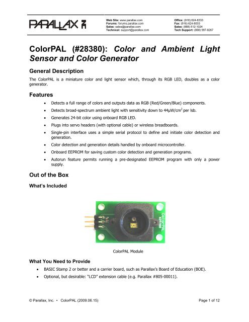
<strong><strong>Color</strong>PAL</strong> Module<br />
• BASIC Stamp 2 or better <strong>and</strong> a carrier board, such as Parallax’s Board of Education (BOE).<br />
• Optional, but desirable: “LCD” extension cable (e.g. Parallax #805-00011).<br />
© Parallax, Inc. • <strong><strong>Color</strong>PAL</strong> (2009.06.15) Page 1 of 12
Quick Start (<strong>Color</strong> Sensing)<br />
1. Hook up your <strong><strong>Color</strong>PAL</strong> as shown below in the Installation section, using P15 for the signal.<br />
2. Download the color match software zip file from the <strong><strong>Color</strong>PAL</strong> product page on parallax.com.<br />
3. Load the program <strong><strong>Color</strong>PAL</strong>_sense.bs2 into your BASIC Stamp <strong>and</strong> RUN it.<br />
4. Close the DEBUG window.<br />
5. Start the program TCS230_<strong><strong>Color</strong>PAL</strong>_match.exe on your PC.<br />
6. Follow the instructions included with the color match zip file.<br />
Quicker Start (<strong>Color</strong> Sensing)<br />
1. Hook up your <strong><strong>Color</strong>PAL</strong> as shown below in the Installation section, using P15 for the signal.<br />
2. Download the BASIC Stamp program, <strong><strong>Color</strong>PAL</strong>_mimic.bs2, <strong>and</strong> RUN it in your BASIC Stamp.<br />
3. Calibrate on black <strong>and</strong> white subjects, using the “b” <strong>and</strong> “w” keys.<br />
4. Sample a color using the “s” key, then look at the LED to see that color being mimicked.<br />
Quickest Start (LED Demo)<br />
1. Hook up your <strong><strong>Color</strong>PAL</strong> as shown below in the Installation section, using P15 for the signal.<br />
2. Download the BASIC Stamp program, <strong><strong>Color</strong>PAL</strong>_transit.bs2, <strong>and</strong> RUN it in your BASIC Stamp.<br />
3. Hold the <strong><strong>Color</strong>PAL</strong> above a white sheet of paper, <strong>and</strong> watch as the LED’s colors change, blending<br />
from one to another. CAUTION: The LED is much too bright <strong>and</strong> concentrated to stare at<br />
directly. Use the above technique to view the color changes.<br />
Principle of Operation<br />
The <strong><strong>Color</strong>PAL</strong> uses an RGB LED to illuminate a sample, one color at a time, along with a broad-spectrum<br />
light-to-voltage converter to measure the light reflected back. The amount of light reflected from the<br />
sample under illumination from each red, green, <strong>and</strong> blue LED can be used to determine the sample’s<br />
color.<br />
The light sensor used in the <strong><strong>Color</strong>PAL</strong> is a TAOS (www.taosinc.com) TSL13T, which has the following<br />
spectral sensitivity curve (taken from the TSL13T datasheet <strong>and</strong> superimposed with the LED<br />
wavelengths:<br />
© Parallax, Inc. • <strong><strong>Color</strong>PAL</strong> (2009.06.15) Page 2 of 12
The sensor outputs a voltage proportional to all the light that it sees, weighted by the above curve.<br />
Therefore, when a subject is illuminated with a red LED only, it will respond with a voltage proportional<br />
to the red component of the subject’s color, <strong>and</strong> similarly with blue <strong>and</strong> green. When there is ambient<br />
light mixed in with the LED’s illumination, its effect can be eliminated by sampling first without any LEDs<br />
turned on, then subtracting this reading, in turn, from each of the red, green, <strong>and</strong> blue components. This<br />
reference measurement should be taken before each color measurement to eliminate any effects from<br />
varying ambient conditions. In the paragraphs that follow, it will be assumed that an ambient reference is<br />
taken <strong>and</strong> subtracted from each measurement discussed.<br />
Because the LED <strong>and</strong> sensor sit next to each other on the <strong><strong>Color</strong>PAL</strong>’s circuit board, <strong>and</strong> because the<br />
plastic snorkel itself reflects some light back (primarily from its threads), the light response from a<br />
completely black subject will be non-zero. For this reason, the black response for each color component<br />
has to be determined experimentally, so that it, too, can be subtracted from the overall response. The<br />
three components thus measured (with an ambient reference subtracted), Kr, Kg, <strong>and</strong> Kb, are known as<br />
the “black reference”. A black reference is typically obtained only once before each measurement session.<br />
The TSL13T light sensor does not respond equally to the red, green, <strong>and</strong> blue LEDs, <strong>and</strong> those LEDs<br />
don’t put out equal amounts of light at the red, green, <strong>and</strong> blue wavelengths. So, in addition to the<br />
ambient reference <strong>and</strong> black reference, it is also necessary to take a “white reference”, wherein the<br />
<strong><strong>Color</strong>PAL</strong> is presented with a completely white surface. Again, after subtracting the ambient lighting, the<br />
red, green, <strong>and</strong> blue components of this reference will be called, Wr, Wg, <strong>and</strong> Wb.<br />
Now we have a way of determining a subject’s actual color as a percentage of the difference between the<br />
white <strong>and</strong> black references. This percentage can be expressed as a value between 0 (0%) <strong>and</strong> 255<br />
(100%), as follows for red, say:<br />
Cr = 255 · (Ur – Kr) / (Wr – Kr) , where<br />
Ur is the uncorrected (except for ambient) reading, <strong>and</strong> Cr is the corrected reading.<br />
Because the <strong><strong>Color</strong>PAL</strong> uses an integrated RGB LED to emit the sampling colors, it is also capable of<br />
generating a wide range of colors in the visible spectrum by means of its onboard microcontroller, which<br />
pulse-width modulates the LED segments to produce 24-bit RGB color.<br />
Comparison to TCS230-DB<br />
The <strong><strong>Color</strong>PAL</strong> <strong>and</strong> TCS230-DB (Parallax #28302) are both capable of detecting colors in the RGB color<br />
space. The <strong><strong>Color</strong>PAL</strong> is designed as an inexpensive sensor for hobby <strong>and</strong> educational use, whereas the<br />
TCS230-DB also finds use in professional <strong>and</strong> OEM color detection applications. The following chart will<br />
help to illustrate the similarities <strong>and</strong> differences between the two devices, as an aid to selecting the<br />
proper one for a given application. The more stars in a given column, the more applicable or desirable<br />
the feature will be.<br />
© Parallax, Inc. • <strong><strong>Color</strong>PAL</strong> (2009.06.15) Page 3 of 12
Feature or Capability <strong><strong>Color</strong>PAL</strong> TCS230-DB<br />
Price <br />
<strong>Color</strong> detection accuracy with normal reflective subjects <br />
<strong>Color</strong> detection accuracy with fluorescent (e.g. Day-Glo,<br />
Astrobrite) reflective subjects<br />
<br />
<br />
<strong>Color</strong> detection on very glossy surfaces <br />
<strong>Color</strong> detection of radiant subjects (e.g. LEDs, CRTs) Not possible <br />
<strong>Color</strong> sensor output Serial I/O Frequency<br />
Pins needed for interface (including +5V <strong>and</strong> ground) 3 6<br />
<strong>Color</strong> detection resolution (per RGB component)<br />
Up to 8 bits, using<br />
onboard 10-bit ADC<br />
8 bits or more,<br />
limited only by<br />
sample time<br />
Compatibility with Parallax’s PC color-matching software <br />
Accurate color detection requires ambient light correction Automatic Yes<br />
Accurate color detection requires white balance Yes Yes<br />
Accurate color detection requires black balance Yes No<br />
<strong>Color</strong> sensing averaged over spot diameter of: 0.47” (12mm) 0.14” (3.5mm)<br />
<strong>Color</strong> generation Not possible<br />
On-board programmable sensing <strong>and</strong> generation sequences None<br />
Installation<br />
The <strong><strong>Color</strong>PAL</strong> requires three connections: regulated +5V supply, ground, <strong>and</strong> open-collector serial data.<br />
It can be plugged directly into a BOE, for example, like so:<br />
Vdd Vin Vss<br />
P15<br />
P14<br />
P13<br />
P12<br />
P11<br />
P10<br />
P9<br />
P8<br />
P7<br />
P6<br />
P5<br />
P4<br />
P3<br />
P2<br />
P1<br />
P0<br />
Using the Parallax “LCD” Extension Cable, it can also be plugged into a servo header:<br />
Sig<br />
+5V<br />
Gnd<br />
IMPORTANT: When connecting to a servo header on the BOE, make sure that the header is jumpered<br />
for Vdd <strong>and</strong> not Vin!<br />
© Parallax, Inc. • <strong><strong>Color</strong>PAL</strong> (2009.06.15) Page 4 of 12
Programming<br />
Communication with the <strong><strong>Color</strong>PAL</strong> takes place using serial I/O, transmitting <strong>and</strong> receiving at between<br />
2400 <strong>and</strong> 7200 baud, using a non-inverted, open-drain protocol. The <strong><strong>Color</strong>PAL</strong> includes a pullup<br />
resistor to Vdd, so you do not need to apply one externally. Because of the open-drain protocol, the pin<br />
used to communicate with the <strong><strong>Color</strong>PAL</strong> should always be configured as an input, except when being<br />
driven low. Also, when starting up, you should wait for this pin to be pulled high by the <strong><strong>Color</strong>PAL</strong> before<br />
trying to send it any comm<strong>and</strong>s. This is particularly important when connecting it to one of the BOE’s<br />
servo headers, since the three-way power switch will start your PBASIC program before powering up the<br />
<strong><strong>Color</strong>PAL</strong>.<br />
The pin <strong>and</strong> baudmode settings for the BS2 on pin 15 at 7200 baud, for example, would be:<br />
sio PIN 15<br />
baud CON 119 + 32768<br />
The <strong><strong>Color</strong>PAL</strong> has several modes of operation:<br />
• Direct: Comm<strong>and</strong>s are received <strong>and</strong> executed immediately.<br />
• Buffering: Comm<strong>and</strong>s are received <strong>and</strong> buffered for future execution.<br />
• Executing: Comm<strong>and</strong>s which were buffered <strong>and</strong>/or saved in EEPROM are being executed.<br />
There are three different ways to reset a <strong><strong>Color</strong>PAL</strong>:<br />
• Powerup: When first powered up, the <strong><strong>Color</strong>PAL</strong> begins executing the comm<strong>and</strong>s saved in its<br />
internal EEPROM at location 00. In a new, unprogrammed <strong><strong>Color</strong>PAL</strong>, this program simply exits<br />
into Direct mode.<br />
• Short Break: A low logic level applied for about 7 milliseconds will reset the <strong><strong>Color</strong>PAL</strong> <strong>and</strong> begin<br />
execution as above for Powerup.<br />
• Long Break: A low logic level applied for 50 milliseconds or more will reset the <strong><strong>Color</strong>PAL</strong> <strong>and</strong><br />
enter Direct mode. This is the only way to grab the <strong><strong>Color</strong>PAL</strong>’s attention when it’s running a<br />
program.<br />
Here is an example of a reset routine that will always cause the <strong><strong>Color</strong>PAL</strong> to enter Direct mode:<br />
Reset:<br />
LOW sio<br />
INPUT sio<br />
DO UNTIL sio : LOOP<br />
LOW sio<br />
PAUSE 50<br />
INPUT sio<br />
PAUSE 10<br />
RETURN<br />
'Pull sio low to eliminate any residual charge.<br />
'Return pin to input.<br />
'Wait for pin to be pulled high by <strong><strong>Color</strong>PAL</strong>.<br />
'Pull pin low.<br />
'Keep low for 50ms to enter Direct mode.<br />
'Return pin to input.<br />
'Pause another 10ms<br />
© Parallax, Inc. • <strong><strong>Color</strong>PAL</strong> (2009.06.15) Page 5 of 12
Direct Comm<strong>and</strong>s<br />
To begin programming the <strong><strong>Color</strong>PAL</strong>, you will need to be in Direct mode. In this mode, the <strong><strong>Color</strong>PAL</strong> will<br />
accept any of four different comm<strong>and</strong>s. These are:<br />
• = (Equal sign): Begin buffering comm<strong>and</strong>s.<br />
• ! (Exclamation point): Begin executing the buffered code.<br />
• # (Pound sign): Save the buffered code to an address in EEPROM.<br />
• + (Plus sign): Receive a “network” address.<br />
= Begin Buffering Comm<strong>and</strong>s<br />
! Execute Buffered Comm<strong>and</strong>s<br />
Any programming (i.e. color-related) comm<strong>and</strong>s that the <strong><strong>Color</strong>PAL</strong> executes must first be buffered before<br />
they can be executed. Here is a typical buffer-<strong>and</strong>-execute sequence that causes the RGB LED to light up<br />
red:<br />
SEROUT sio, baud, ["= R !"]<br />
Note: Any blanks embedded within a buffered comm<strong>and</strong> sequence (i.e. after the “=” <strong>and</strong> before a “!” or<br />
“#”) are optional <strong>and</strong> can be added to enhance program readability. Adding them affects neither the<br />
speed of a program nor the amount of memory it requires. However, do not embed blanks in a direct<br />
comm<strong>and</strong> sequence! Doing so will cause the <strong><strong>Color</strong>PAL</strong>’s automatic baud rate detection to fail.<br />
#nn Save Buffered Program to EEPROM<br />
Saving a program to EEPROM requires an address to be supplied in hexadecimal <strong>and</strong> ranging from 00 to<br />
3F. All numerical arguments passed to the <strong><strong>Color</strong>PAL</strong> are done so as two-digit hexadecimal constants (00<br />
to FF). To store the “light up red” program to EEPROM location zero (for automatic startup), say, you’d<br />
do this:<br />
SEROUT sio, baud, ["= R #00"]<br />
This, along with the prior example, also illustrates that both the execute (!) <strong>and</strong> save (#) comm<strong>and</strong>s will<br />
immediately exit Buffer mode <strong>and</strong> enter Direct mode.<br />
IMPORTANT: If the program you save starts automatically (i.e. is stored at location 00) <strong>and</strong> outputs<br />
data, it will do so at an uncalibrated baud rate, somewhere around 4800 baud. The reason is that the<br />
<strong><strong>Color</strong>PAL</strong> calibrates its baud rate from comm<strong>and</strong>s sent to it in Direct mode. Lacking any such comm<strong>and</strong>s<br />
when autostarting, it has to pick a default value. Because the <strong><strong>Color</strong>PAL</strong> uses an RC oscillator for its<br />
timebase, it’s hard to predict with any degree of accuracy what the actual output baud rate will be.<br />
There are two ways around this. One is to restart the stored program manually by entering Direct mode<br />
<strong>and</strong> issuing an Execute comm<strong>and</strong>. The <strong><strong>Color</strong>PAL</strong> will pick up the desired baud rate from this.<br />
The other option is to auto-detect the baud rate at which the <strong><strong>Color</strong>PAL</strong> is transmitting <strong>and</strong> use it instead.<br />
Here’s a PBASIC program that will do that. It will work with any BASIC Stamp, except the BS2px:<br />
© Parallax, Inc. • <strong><strong>Color</strong>PAL</strong> (2009.06.15) Page 6 of 12
' {$STAMP BS2}<br />
' {$PBASIC 2.5}<br />
sio PIN 15<br />
baud VAR Word<br />
pwidth VAR Word<br />
i VAR Byte<br />
PAUSE 100<br />
baud = $ffff<br />
FOR i = 0 TO 255<br />
PULSIN sio, 0, pwidth<br />
baud = baud MAX pwidth<br />
NEXT<br />
baud = baud
DO<br />
SEROUT sio, baud, ["+01= G !+02= B !"] : PAUSE 1000<br />
SEROUT sio, baud, ["+01= B !+02= G !"] : PAUSE 1000<br />
SEROUT sio, baud, ["+00= R !"] : PAUSE 1000<br />
LOOP<br />
Program Comm<strong>and</strong>s<br />
While the <strong><strong>Color</strong>PAL</strong> is in Buffering mode, you can enter the comm<strong>and</strong>s that actually do something, like<br />
light up the LEDs or take a color sample. Here are the comm<strong>and</strong>s that it can accept.<br />
— LED Comm<strong>and</strong>s —<br />
WARNING! The light from the RGB LED is very concentrated <strong>and</strong> can be very bright. Just as you would<br />
not stare at the sun (<strong>and</strong> for the same reason), do not stare directly at the LED.<br />
rnnnnnn<br />
Display RGB <strong>Color</strong> on LED<br />
A lowercase r followed by six hex digits will cause the LED to display the selected color components, with<br />
00 being fully “off”, FF being fully “on”, <strong>and</strong> numbers in between representing various intermediate<br />
intensities. To display the color orange, for example, you can send the following comm<strong>and</strong>:<br />
SEROUT sio, baud, ["= rC04000 !"]<br />
This causes the red LED segment to light up at 75% intensity (C0) <strong>and</strong> the green segment to light at<br />
25% intensity (40). The blue segment remains “off” (00).<br />
A - Z<br />
Display Named <strong>Color</strong> on LED<br />
The uppercase letters represent predefined color names. These are, in order by hue (with letter<br />
designators in boldface, along with their hexadecimal equivalents):<br />
<strong>Color</strong> Hex <strong>Color</strong> Hex<br />
Red FF0000 roSe E00020<br />
Tangerine E02000 Pink C00040<br />
Orange C04000 orchiD A00060<br />
Flame A06000 Magenta 800080<br />
Yellow 808000 Amethyst 6000A0<br />
cHartreuse 60A000 Violet 4000C0<br />
Lime 40C000 Indigo 2000E0<br />
Emerald 20E000 Blue 0000FF<br />
Green 00FF00 sKy 0020E0<br />
Jade 00E020 aZure 0040C0<br />
maNganese 00C040 tUrquoise 0060A0<br />
aQua 00A060 Cyan 008080<br />
X LED Off 000000 White 555555<br />
For example, to display the color “jade”, you’d send the following:<br />
SEROUT sio, baud, ["= J !"]<br />
© Parallax, Inc. • <strong><strong>Color</strong>PAL</strong> (2009.06.15) Page 8 of 12
tnn<br />
Set Inter-color Transition Time<br />
By default, when colors are displayed in sequence, it’s done one color after the other without any kind of<br />
transition. This behavior can be modified by setting a non-zero transition time between colors. The twohex-digit<br />
argument accompanying this comm<strong>and</strong> establishes the rate at which one color blends into the<br />
next during a transition. The overall transition time depend on how dissimilar the two colors are to begin<br />
with. <strong>Color</strong>s whose RGB components differ by a lot will take more time in their transition than those<br />
whose components are closer. Here’s an example of red blending into blue:<br />
SEROUT sio, baud, ["= R tC0 B !"]<br />
— <strong>Light</strong> Sensing Comm<strong>and</strong>s —<br />
s Sample Output from <strong>Light</strong> <strong>Sensor</strong> Returns: nnn<br />
The <strong><strong>Color</strong>PAL</strong> incorporates a 10-bit analog-to-digital converter to read the voltage output from the<br />
TSL13T light sensor. When the sample comm<strong>and</strong> is executed, it takes a reading then outputs it as three<br />
hexadecimal digits. Here is how you might take a green color reading, subtracting the ambient light, for<br />
example:<br />
Red VAR Word<br />
Grn VAR Word<br />
Blu VAR Word<br />
Amb VAR Word<br />
...<br />
SEROUT sio, baud, ["= X s !"]<br />
SERIN sio, baud, [HEX3 Amb]<br />
SEROUT sio, baud, ["= G s !"]<br />
SERIN sio, baud, [HEX3 Grn]<br />
Grn = Grn – Amb<br />
IMPORTANT: When sampling colors with the LED on, use only pure, fully-saturated colors such as R, G,<br />
<strong>and</strong> B. The reason is that color blends use pulse-width modulation to attain the different shades, <strong>and</strong> the<br />
sensor is fast enough not to average what it sees over the PWM period. With pure colors, the LED is on<br />
constantly, so this is not an issue.<br />
m Multi-sample RGB colors Returns: nnnnnnnnn<br />
This macro function performs an ambient light measurement, then individual measurements with each of<br />
the red, green, <strong>and</strong> blue LEDs, subtracting the ambient reading from each. It then outputs three 3-digit<br />
hex numbers representing the ambient-corrected red, green, <strong>and</strong> blue readings. Here’s an example:<br />
Red VAR Word<br />
Grn VAR Word<br />
Blu VAR Word<br />
...<br />
SEROUT sio, baud, ["= m !"]<br />
SERIN sio, baud, [HEX3 Red, HEX3 Grn, HEX3 Blu]<br />
h<br />
l<br />
Select High Sensitivity<br />
Select Low Sensitivity<br />
© Parallax, Inc. • <strong><strong>Color</strong>PAL</strong> (2009.06.15) Page 9 of 12
The <strong><strong>Color</strong>PAL</strong> normally references the full-scale output of the light sensor to +5V. For very low-light<br />
situations, this output can be referenced to 1.1V instead, which effectively multiplies the sensitivity by<br />
more than 4.5. This setting is not recommended for normal ambient lighting conditions or cases where<br />
the internal LED is used to illuminate a subject. This is because the reading will saturate just from the<br />
ambient light or reflections from the plastic snorkel. But for low-ambient conditions with external color<br />
illumination, the high sensitivity setting may well be useful. As a complement, the low sensitivity<br />
comm<strong>and</strong> can be used to return to the default setting.<br />
In the following example, a sample is taken at high sensitivity, returning to low sensitivity when finished:<br />
SEROUT sio, baud, ["= h s l!"]<br />
SERIN sio, baud, [HEX3 Value]<br />
pnn Pause<br />
— Program Flow <strong>and</strong> Miscellaneous Comm<strong>and</strong>s —<br />
The pause comm<strong>and</strong> takes a two-hex-digit argument <strong>and</strong> pauses execution for time approximately equal<br />
to nn · 5ms. Here’s an example that displays yellow, cyan, <strong>and</strong> magenta each for one second, then<br />
fades to black:<br />
SEROUT sio, baud, ["= Y pC8 C pC8 M pC8 t50 X !"]<br />
(nn<br />
Begin a Program Loop<br />
) End a Program Loop<br />
This comm<strong>and</strong> pair defines a loop within a program. The “begin” comm<strong>and</strong> takes a two-hex-digit<br />
argument, which tells how many times the loop is to be executed. If this amount is 00 the loop is<br />
executed infinitely. Loops can be nested. Here’s an example that alternates between red <strong>and</strong> green ten<br />
times, finishing with a transition to blue:<br />
SEROUT sio, baud, ["= (0A R p64 G p64 ) t50 B !"]<br />
>nn Call a Subroutine in EEPROM<br />
Programs saved with the #nn direct comm<strong>and</strong> can be called as subroutines from a running program. The<br />
two-hex-digit argument (00 – 3F) specifies the EEPROM address of the program to call. In this example,<br />
the program from the prior example is called as a subroutine, then its blue finale slowly fades to black:<br />
SEROUT sio, baud, ["= (0A R p64 G p64 ) t50 B #20"]<br />
PAUSE 100<br />
SEROUT sio, baud, ["= >20 tFF X !"]<br />
The PAUSE statement is in there because the micro requires some time to store the program. Without it,<br />
the following SEROUT would occur too soon, <strong>and</strong> the <strong><strong>Color</strong>PAL</strong> would ignore it.<br />
?nn<br />
Set R<strong>and</strong>om Deviation<br />
Sometimes it’s nice to mix things up a little for certain color displays (e.g. flickering c<strong>and</strong>les). The set<br />
r<strong>and</strong>om deviation comm<strong>and</strong> (?) lets you do just that. The parameter following the question mark is kept<br />
as the current r<strong>and</strong>om deviate. Once it’s been established, any subsequent parameter to the pause,<br />
transition-time, rgb-color, <strong>and</strong> (loop) comm<strong>and</strong>s will be affected by r<strong>and</strong>omization. It works as follows:<br />
© Parallax, Inc. • <strong><strong>Color</strong>PAL</strong> (2009.06.15) Page 10 of 12
1. If the parameter is even, it is taken as a minimum, to which a r<strong>and</strong>om number between 0 <strong>and</strong><br />
(deviate – 1) is added. The sum cannot go above FE.<br />
2. If the parameter is odd, it is taken as a maximum, to which a r<strong>and</strong>om number between 0 <strong>and</strong><br />
(deviate – 1) is subtracted. The sum cannot go below 01.<br />
To turn off r<strong>and</strong>omization, just do a ?00. In the following example, completely r<strong>and</strong>om colors blend<br />
together ad infinitum:<br />
SEROUT sio, baud, ["= t40 (00 ?FF r000000 ?00 p11) !"]<br />
There are a few things to point out here: 1) the t40 is not r<strong>and</strong>omized, since it occurs before the “?FF”;<br />
2) the loop constant remains at 00 because it’s loaded only once, when the loop begins, <strong>and</strong> placed on<br />
the stack; <strong>and</strong> 3) the p11 is not r<strong>and</strong>omized, since it occurs after the ?00.<br />
Because this example produces so many unsaturated (i.e. whitish) colors, it’s pretty boring. Here’s an<br />
example that will produce fully-saturated colors at the end of each transition, since one component is<br />
always held at nearly zero:<br />
SEROUT sio, baud, ["= t10 (00 ?FF (07 r808001) (07 r800180) (07 r018080) )<br />
!"]<br />
v Get Firmware Version Number Returns: nn<br />
The version comm<strong>and</strong> allows you to get the version number of the <strong><strong>Color</strong>PAL</strong>’s firmware. Version numbers<br />
are output as two hex digits, begin at 01, <strong>and</strong> will increment by one with each new version. Version<br />
changes are expected to be infrequent. The following program reads <strong>and</strong> prints the current version<br />
number:<br />
Version VAR Byte<br />
SEROUT sio, baud, ["= v !"]<br />
SERIN sio, baud, [HEX2 version]<br />
DEBUG "Current version is: ", DEC version, "."<br />
“other” Echo Miscellaneous Character Returns: “other”<br />
Any ASCII character not mentioned here will be buffered <strong>and</strong> simply echoed when the program runs. This<br />
can be h<strong>and</strong>y for synchronizing the BASIC Stamp to a free-running <strong><strong>Color</strong>PAL</strong>’s output. For example, you<br />
could program the <strong><strong>Color</strong>PAL</strong>’s EEPROM to sense <strong>and</strong> output a continuous stream of color data, like so:<br />
SEROUT sio, baud, ["= (00 $ m) #00"]<br />
Then your program can simply sync on the “$” in the data stream to catch the next available sequence of<br />
color data, thus:<br />
SERIN sio, baud, [WAIT("$"), HEX3 red, HEX3 grn, HEX3 blu]<br />
Be sure to read the important note in the “Save Buffered Program to EEPROM” section regarding baud<br />
rates.<br />
Program Limitations<br />
The space available for user programs in the <strong><strong>Color</strong>PAL</strong> is limited by the onboard micro’s RAM <strong>and</strong><br />
EEPROM space. The space available for buffering programs is 40 bytes. The amount of space required in<br />
the buffer for each comm<strong>and</strong> is one byte, plus one byte for every two-digit numerical parameter it<br />
requires. The space available in the EEPROM is 64 bytes, including the byte at the end that determines<br />
the unit number. Spaces are not buffered <strong>and</strong> do not count toward the memory occupied by a program.<br />
© Parallax, Inc. • <strong><strong>Color</strong>PAL</strong> (2009.06.15) Page 11 of 12
Deeply- or incorrectly-nested subroutine calls <strong>and</strong> loops may cause the stack to encroach upon the end of<br />
the buffer space in RAM. Each call adds one byte to the stack; each loop, two bytes. There is no error<br />
checking for excess nesting or unterminated loops. It is the programmer’s responsibility to ensure that<br />
programs are correctly structured.<br />
<strong>Color</strong> Matching Program<br />
The Parallax website includes a PC color-matching program that you can use to demo your <strong><strong>Color</strong>PAL</strong>. The<br />
zip file includes the exe file for the PC, a BASIC Stamp program for the <strong><strong>Color</strong>PAL</strong>, <strong>and</strong> a couple BASIC<br />
Stamp programs for the TCS230-DB, along with some documentation.<br />
Schematic<br />
+5V<br />
LED1<br />
OVSARGB3R8<br />
B<br />
RP1<br />
4 x 68R<br />
G<br />
R<br />
J1<br />
+5V<br />
C1<br />
10µF<br />
R1<br />
10K<br />
R2<br />
330R<br />
U1<br />
1 N/C OUT 4<br />
2 Gnd Vdd 3<br />
TSL13T<br />
U2<br />
1<br />
8<br />
/RST Vdd<br />
2<br />
7<br />
PB.3 PB.2<br />
3 PB.4 PB.1 6<br />
4 5<br />
Gnd PB.0<br />
ATTiny13A<br />
+5V<br />
C2<br />
0.1µF<br />
© Parallax, Inc. • <strong><strong>Color</strong>PAL</strong> (2009.06.15) Page 12 of 12