Grafik Eye RK-CS - Lutron Lighting Installation Specialists
Grafik Eye RK-CS - Lutron Lighting Installation Specialists
Grafik Eye RK-CS - Lutron Lighting Installation Specialists

You also want an ePaper? Increase the reach of your titles
YUMPU automatically turns print PDFs into web optimized ePapers that Google loves.
TM<br />
®<br />
TM<br />
®<br />
Data A OK<br />
TM<br />
Data B OK<br />
w/Zone Capture TM<br />
Data B OK<br />
w/Zone Capture TM<br />
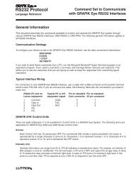
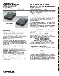
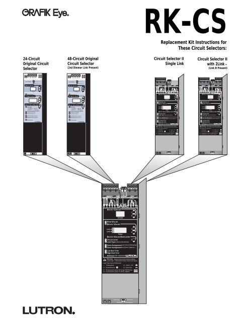
<strong>RK</strong>-<strong>CS</strong><br />
Replacement Kit Instructions for<br />
These Circuit Selectors:<br />
24-Circuit<br />
Original Circuit<br />
Selector<br />
48-Circuit Original<br />
Circuit Selector<br />
(2nd Dimmer Link Present)<br />
Circuit Selector II<br />
Single Link<br />
Circuit Selector II<br />
with 2Link <br />
(Link B Present)<br />
1 2 3 4 5<br />
1 2 3 4 5<br />
Link Status<br />
Power OK (Pins 1,2)<br />
Link Status<br />
Power OK (Pins 1,2)<br />
1 2 3 4 D 5<br />
1 2 3 4 5 D C D<br />
Data OK (Pins 3,4)<br />
Data OK (Pins 3,4)<br />
SELECT CIRCUIT<br />
SELECT CIRCUIT<br />
Data A OK<br />
Power OK<br />
Data A OK<br />
Power OK<br />
Circuit<br />
VIEW VALUE<br />
SELECT VALUE<br />
1<br />
2<br />
3<br />
Circuit<br />
VIEW VALUE<br />
SELECT VALUE<br />
1<br />
2<br />
3<br />
Common<br />
24VFW<br />
MUX<br />
MUX<br />
Drain<br />
Sense<br />
Comm<br />
Link Link<br />
A B<br />
SELECT CIRCUIT<br />
1<br />
2<br />
Circuit<br />
MUX<br />
MUX<br />
Drain<br />
1 2 3 4 D 5 C D<br />
Common<br />
24VFW<br />
MUX<br />
MUX<br />
Drain<br />
Sense<br />
Comm<br />
Link Link<br />
A B<br />
SELECT CIRCUIT<br />
1<br />
2<br />
Circuit<br />
MUX<br />
MUX<br />
Drain<br />
1 2 3 4 D 5 C D<br />
4<br />
Value<br />
SELECT VALUE DISPLAYED<br />
4<br />
Value<br />
SELECT VALUE DISPLAYED<br />
VIEW VALUE<br />
SELECT VALUE<br />
VIEW VALUE<br />
SELECT VALUE<br />
Load Type<br />
1 Inc/Mag LV 4 Non-dim<br />
2 Fluorescent 5 Elec. LV<br />
3 Neon/CC – Unassigned<br />
Control and Zone Assigned<br />
Using circuit schedule<br />
Using Zone Capture<br />
Low End Trim (optional)<br />
High End Trim (optional)<br />
Load Type<br />
1 Inc/Mag LV 4 Non-dim<br />
2 Fluorescent 5 Elec. LV<br />
3 Neon/CC – Unassigned<br />
Control and Zone Assigned<br />
Using circuit schedule<br />
Using Zone Capture<br />
Low End Trim (optional)<br />
High End Trim (optional)<br />
Link A<br />
Link B<br />
Value<br />
SELECT VALUE DISPLAYED<br />
Circuit Level<br />
Load Type (See Instructions)<br />
Zone Assignment w/ Circuit Schedule<br />
Zone Assignment<br />
3<br />
4<br />
5<br />
Link A<br />
Link B<br />
Value<br />
SELECT VALUE DISPLAYED<br />
Circuit Level<br />
Load Type (See Instructions)<br />
Zone Assignment w/ Circuit Schedule<br />
Zone Assignment<br />
3<br />
4<br />
5<br />
Circuit Level<br />
Circuit Level<br />
Low-End Trim<br />
High-End Trim<br />
Low-End Trim<br />
High-End Trim<br />
Address ('Ad' displayed)<br />
Address ('Ad' displayed)<br />
Warning - Read instructions before setting<br />
Load Type. Instructions show more load types.<br />
Warning - Read instructions before setting<br />
Load Type. Instructions show more load types.<br />
Load Type Quick Reference:<br />
Load Type Quick Reference:<br />
--- Unassigned<br />
3-1<br />
Neon / CC<br />
--- Unassigned<br />
3-1<br />
Neon / CC<br />
1-1 Incandescent<br />
4-1 Non-Dim<br />
1-1 Incandescent<br />
4-1 Non-Dim<br />
2-1 Fluorescent <strong>Lutron</strong> Hi-lume FDB Ballast<br />
2-2 Fluorescent <strong>Lutron</strong> Tu-Wire TM Ballast<br />
2-1 Fluorescent <strong>Lutron</strong> Hi-lume FDB Ballast<br />
2-2 Fluorescent <strong>Lutron</strong> Tu-Wire TM Ballast<br />
(Non-Ess)<br />
(Essential)<br />
(Non-Ess)<br />
(Essential)<br />
Normal<br />
Emergency<br />
Normal<br />
Emergency<br />
1 2 3 4 D 5 C D<br />
Power OK<br />
Data B OK<br />
Common<br />
24VFW<br />
MUX<br />
MUX<br />
Drain<br />
Sense<br />
Link Link<br />
A B<br />
Comm<br />
SELECT CIRCUIT<br />
1<br />
MUX<br />
MUX<br />
Drain<br />
1 2 3 4 D 5 C D<br />
Circuit<br />
2<br />
VIEW VALUE<br />
SELECT VALUE<br />
Link A<br />
Link B<br />
Value<br />
3<br />
4<br />
SELECT VALUE DISPLAYED<br />
Circuit Level<br />
Load Type (See Instructions)<br />
Zone Assignment w/ Circuit Schedule<br />
Zone Assignment w/Zone Capture<br />
Low-End Trim<br />
High-End Trim<br />
Address ('Ad' displayed)<br />
Warning Read instructions before setting<br />
Load Type. Instructions show more load types.<br />
Load Type Quick Reference:<br />
--- Unassigned<br />
3-1 Neon / CC<br />
1-1 Incandescent<br />
4-1 Non-Dim<br />
2-1 Fluorescent <strong>Lutron</strong> Hi-lume FDB Ballast<br />
2-2 Fluorescent <strong>Lutron</strong> Tu-Wire TM Ballast<br />
5<br />
(Non-Ess)<br />
Normal<br />
(Essential)<br />
Emergency
LP-RPM-4U<br />
-120<br />
Listed 243C<br />
Ind. Cont. Eq.<br />
500-xxxx<br />
LUTRON R<br />
Coopersburg USA<br />
Main Feed:<br />
120VAC<br />
50/60 Hz<br />
Input Current :<br />
16A maximum<br />
Load Current:<br />
16A (TOTAL of<br />
4 loads)<br />
Load Types :<br />
Incandescent,<br />
Magnetic<br />
Low Voltage,<br />
Non-Dim, or<br />
Neon<br />
LED diagnosis:<br />
Slow Blink<br />
=OK, Fast<br />
Blink=No Data<br />
Address<br />
1<br />
8<br />
Switch<br />
Class 2<br />
Control<br />
Harness<br />
1/96<br />
1 2 3 4 D 5 C D<br />
Data A OK<br />
Power OK Data B OK<br />
Link Link<br />
1 2 3 4 D 5 A B C D<br />
SELECT CIRCUIT<br />
1<br />
2<br />
Common<br />
24VFW<br />
MUX<br />
Link A<br />
Link B<br />
MUX<br />
Drain<br />
Sense<br />
VIEW VALUE<br />
SELECT VALUE<br />
Circuit<br />
Comm<br />
MUX<br />
Value<br />
SELECT VALUE DISPLAYED<br />
Circuit Level<br />
5<br />
Load Type (See Instructions)<br />
Zone Assignment w/ Circuit Schedule<br />
Zone Assignment w/Zone Capture TM<br />
Low-End Trim<br />
High-End Trim<br />
Address ('Ad' displayed)<br />
Warning - Read instructions before setting the<br />
Load Type. Instructions show more load types.<br />
Load Type Quick Reference:<br />
--- Unassigned<br />
3-1 Neon / CC<br />
1-1 Incandescent<br />
4-1 Non-Dim<br />
2-1 Fluorescent <strong>Lutron</strong> Hi-lume FDB Ballast<br />
2-2 Fluorescent <strong>Lutron</strong> Tu-Wire TM Ballast<br />
(Non-Ess)<br />
Normal<br />
3<br />
4<br />
(Essential)<br />
Emergency<br />
MUX<br />
Drain<br />
1 2 3 4 D 5 C D<br />
Data A OK<br />
Power OK Data B OK<br />
Link Link<br />
1 2 3 4 D 5 C D<br />
SELECT CIRCUIT<br />
1<br />
2<br />
Circuit<br />
24VFW<br />
MUX<br />
MUX<br />
Drain<br />
Sense<br />
VIEW VALUE<br />
SELECT VALUE<br />
Link A<br />
Link B<br />
1 2 3 4 D 5 C D<br />
Data A OK<br />
Power OK Data B OK<br />
Link Link<br />
1 2 3 4 D 5 A B C D<br />
SELECT CIRCUIT<br />
1<br />
2<br />
Common<br />
24VFW<br />
MUX<br />
MUX<br />
Drain<br />
Sense<br />
Circuit<br />
Link A<br />
3<br />
Link B<br />
4<br />
Value<br />
SELECT VALUE DISPLAYED<br />
Circuit Level<br />
5<br />
Load Type (See Instructions)<br />
Zone Assignment w/ Circuit Schedule<br />
Zone Assignment w/Zone Capture TM<br />
Low-End Trim<br />
High-End Trim<br />
Address ('Ad' displayed)<br />
Warning - Read instructions before setting the<br />
Load Type. Instructions show more load types.<br />
Load Type Quick Reference:<br />
--- Unassigned<br />
3-1 Neon / CC<br />
1-1 Incandescent<br />
4-1 Non-Dim<br />
2-1 Fluorescent <strong>Lutron</strong> Hi-lume FDB Ballast<br />
2-2 Fluorescent <strong>Lutron</strong> Tu-Wire TM Ballast<br />
Comm<br />
MUX<br />
Value<br />
SELECT VALUE DISPLAYED<br />
Circuit Level<br />
5<br />
Load Type (See Instructions)<br />
Low-End Trim<br />
High-End Trim<br />
Address ('Ad' displayed)<br />
Warning - Read instructions before setting<br />
Load Type. Instructions show more load types.<br />
Load Type Quick Reference:<br />
--- Unassigned<br />
3-1 Neon / CC<br />
1-1 Incandescent<br />
4-1 Non-Dim<br />
2-1 Fluorescent <strong>Lutron</strong> Hi-lume FDB Ballast<br />
2-2 Fluorescent <strong>Lutron</strong> Tu-Wire TM Ballast<br />
Comm<br />
MUX<br />
3<br />
4<br />
MUX<br />
Drain<br />
Zone Assignment w/ Circuit Schedule<br />
Zone Assignment w/Zone Capture TM<br />
MUX<br />
Drain<br />
(Non-Ess)<br />
Normal<br />
D25<br />
079-226<br />
Each of four switching circuits rated for:<br />
16A continuous max.<br />
100 through 277VAC 50/60 Hz<br />
1/3 HP at 120VAC, 1/2HP at 277VAC<br />
CAUTION - Risk of Electric Shock - More than<br />
one disconnect switch may be required to<br />
de-energize the equipment before servicing.<br />
Listed 243C<br />
Ind. Cont. Eq.<br />
COOPERSBURG, PA 18036 USA<br />
VIEW VALUE<br />
SELECT VALUE<br />
(Non-Ess)<br />
Normal<br />
(Essential)<br />
Emergency<br />
(Essential)<br />
Emergency<br />
N<br />
N<br />
H<br />
H<br />
2122 2A2B<br />
R<br />
S<br />
T<br />
TEST<br />
NORMAL<br />
1 2 3 4 D 5 C D<br />
Data A OK<br />
Power OK Data B OK<br />
Link Link<br />
1 2 3 4 D 5 C D<br />
SELECT CIRCUIT<br />
1<br />
2<br />
Circuit<br />
24VFW<br />
MUX<br />
MUX<br />
Drain<br />
Sense<br />
VIEW VALUE<br />
SELECT VALUE<br />
Link A<br />
Link B<br />
Comm<br />
MUX<br />
Value<br />
SELECT VALUE DISPLAYED<br />
Circuit Level<br />
5<br />
Load Type (See Instructions)<br />
Low-End Trim<br />
High-End Trim<br />
Address ('Ad' displayed)<br />
Warning - Read instructions before setting<br />
Load Type. Instructions show more load types.<br />
Load Type Quick Reference:<br />
--- Unassigned<br />
3-1 Neon / CC<br />
1-1 Incandescent<br />
4-1 Non-Dim<br />
2-1 Fluorescent <strong>Lutron</strong> Hi-lume FDB Ballast<br />
2-2 Fluorescent <strong>Lutron</strong> Tu-Wire TM Ballast<br />
3<br />
4<br />
MUX<br />
Drain<br />
Zone Assignment w/ Circuit Schedule<br />
Zone Assignment w/Zone Capture TM<br />
(Non-Ess)<br />
Normal<br />
(Essential)<br />
Emergency<br />
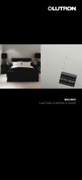
Overview<br />
<strong>Lighting</strong> Control Panels with Circuit Selectors<br />
GP<br />
Replacement Circuit Selector<br />
Common<br />
A B<br />
Dimmer Card<br />
LP<br />
Dimming Module<br />
JDP<br />
Dimmer Card<br />
Replacement<br />
Circuit Selector<br />
Common<br />
A B<br />
Replacement Circuit Selector<br />
XP<br />
Softswitch Module<br />
XP<br />
XP Panel Switching Module<br />
Replacement Circuit Selector<br />
2
Believe it<br />
Believe it<br />
or not, this i su<br />
or not, this i su<br />
posed to l ok like a dictionary!<br />
posed to l ok like a dictionary!<br />
July 6,<br />
Nye, 1995.<br />
July 6,<br />
Nye,<br />
M.<br />
1995,<br />
M.<br />
Brent<br />
Brent<br />
by<br />
by<br />
created<br />
created<br />
was<br />
was<br />
icon<br />
icon<br />
This<br />
This<br />
under<br />
the<br />
direction of Derek R. Thomas.<br />
This icon was created by Brent M. Nye, July 6, 1995.<br />
Believe it<br />
or not, this i su<br />
posed to l ok like a dictionary!<br />
This icon was created by Brent M. Nye, July 6, 1995.<br />
Believe it<br />
Believe it<br />
or not, this i su<br />
or not, this i su<br />
posed to l ok like a dictionary!<br />
posed to l ok like a dictionary!<br />
6, July 1995.<br />
Nye,<br />
6, July 1995.<br />
Nye,<br />
M.<br />
M.<br />
Brent<br />
Brent<br />
by<br />
by<br />
created<br />
created<br />
was<br />
was<br />
icon<br />
icon<br />
This<br />
This<br />
under<br />
the<br />
direction of Derek R. Thomas.<br />
This icon was created by Brent M. Nye, July 6, 1995.<br />
Believe it<br />
or not, this i su<br />
posed to l ok like a dictionary!<br />
This icon was created by Brent M. Nye, July 6, 1995.<br />
Table of Contents<br />
Step-by-Step Instructions<br />
Page<br />
STEP 1: Confirm Status of Existing Circuit Selector ......................4<br />
STEP 2: Record Present Data .....................................................5-8<br />
STEP 3: Remove Wiring from Existing Circuit Selector............ 9-10<br />
STEP 4: Remove Existing Circuit Selector...............................11-12<br />
STEP 5: Mount Replacement Circuit Selector................................13<br />
STEP 6: Rewire Replacement Circuit Selector...............................14<br />
STEP 7: Activate Replacement Circuit Selector..............................15<br />
STEP 8: Change Baud Rate...........................................................16<br />
STEP 9: Re-enter Settings ........................................................... 17<br />
STEP 10 Change Circuit Range (optional) ....................................18<br />
STEP 11 Change Circuit Offset (optional)......................................19<br />
Reference Section<br />
Page<br />
Circuit Directory .................................................................................20<br />
Optional Functions............................................................................. 21<br />
Troubleshooting Guide ......................................................................22<br />
Special Notes<br />
Text following this icon indicates instructions<br />
for an Original Circuit Selector<br />
(24 or 48-circuit).<br />
Text following this icon indicates instructions<br />
for a Circuit Selector II (Single or 2Link).<br />
3
Confirm Status of Existing<br />
Circuit Selector<br />
It may be possible to retrieve settings from the existing<br />
Circuit Selector and reenter them into the Replacement<br />
Circuit Selector. To determine this, proceed with the<br />
following steps.<br />
STEP 1:<br />
Confirm Status of Existing<br />
Circuit Selector<br />
A. Cycle power to ensure consistency with the<br />
following steps.<br />
1. Turn control breaker ‘C’ OFF.<br />
2. Wait 10 seconds.<br />
3. Turn control breaker ‘C’ back ON.<br />
Warning! For GP3, GP4 (breakers provided by<br />
customer), or LP Panel, the input breaker of<br />
Circuit 1 powers the control wiring as well as<br />
Circuit 1's dimmer and load.<br />
STOP<br />
■<br />
■<br />
C<br />
If you are performing an upgrade and the<br />
existing Circuit Selector is working properly,<br />
skip Step 1 and proceed to Step 2.<br />
If one of the following products are used, it<br />
may be possible to download the setup<br />
data to the Replacement Circuit Selector:<br />
Liaison , <strong>Grafik</strong> 5000 , <strong>Grafik</strong> 6000®, or<br />
HomeWorks Interactive . Call <strong>Lutron</strong> for<br />
details.<br />
OFF<br />
Wait<br />
10 sec.<br />
C<br />
ON<br />
4. If the displays read “ord” or “Lc,” the<br />
unit may be working properly. Please call the<br />
<strong>Lutron</strong> Technical Assistance Hotline at<br />
1-800-523-9466.<br />
SELECT CIRCUIT<br />
1<br />
2<br />
Circuit<br />
VIEW VALUE<br />
SELECT VALUE<br />
3<br />
4<br />
Value<br />
SELECT VALUE DISPLAYED<br />
Common<br />
24VFW<br />
MUX<br />
MUX<br />
Drain<br />
Sense<br />
Link Link<br />
A B<br />
Comm<br />
MUX<br />
MUX<br />
Drain<br />
1 2 3 4 D 5 C D<br />
SELECT CIRCUIT<br />
1<br />
2<br />
Circuit<br />
VIEW VALUE<br />
SELECT VALUE<br />
Link A<br />
3<br />
Link B<br />
4<br />
Value<br />
B. Activate Circuit display to check status.<br />
1. Press and release button 1.<br />
■ If the Circuit display reads “1”, proceed to<br />
Step 2.<br />
■ If the displays are empty and the Power OK<br />
LED is ON, the data cannot be retrieved.<br />
Proceed to Step 3.<br />
Power OK LED<br />
1 2 3 4 5<br />
Power OK (Pins 1,2)<br />
Link Status<br />
Data OK (Pins 3,4)<br />
SELECT CIRCUIT<br />
1<br />
2<br />
Circuit<br />
VIEW VALUE<br />
SELECT VALUE<br />
1 2 3 4 D 5 C D<br />
Common<br />
24VFW<br />
MUX<br />
Data A OK<br />
MUX<br />
Drain<br />
Sense<br />
Link Link<br />
A B<br />
Circuit<br />
Power OK<br />
Comm<br />
MUX<br />
1<br />
2<br />
Data B OK<br />
1 2 3 4 D 5 C D<br />
SELECT CIRCUIT<br />
VIEW VALUE<br />
SELECT VALUE<br />
Power OK LED<br />
MUX<br />
Drain<br />
4
Record Present Data<br />
STEP 2: Record Present Data<br />
■<br />
Use the Circuit Directory in the Reference<br />
Section while following the steps below to<br />
record the present data.<br />
STOP<br />
The Link A or B Hierarchy and Zone X<br />
columns are necessary only if the Circuit<br />
Selector you are replacing uses the 2Link<br />
option. To find instructions on how to<br />
view this information, refer to the<br />
2Link Options section of the GP<br />
<strong>Installation</strong> Guide included with this<br />
kit.<br />
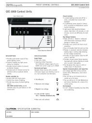
A. View and record load types.<br />
1. Press button 5 repeatedly until the Load Type<br />
LED lights.<br />
■ Use buttons 1 and 2 to view the present Load<br />
Type of each circuit in the Value display and<br />
record the data in the Circuit Directory.<br />
■ Note that ‘ - ’ or ‘ - - - ’ in the Value display<br />
means that the circuit’s load type is unassigned.<br />
Example below: Circuit “1” has a load type of 1<br />
(Circuit Selector II has a load type equivalent of<br />
1-1. See conversion chart on page 6.)<br />
SELECT CIRCUIT<br />
SELECT VALUE DISPLAYED<br />
Load Type<br />
1 Inc/Mag LV<br />
2 Fluorescent<br />
3 Neon/CC<br />
Circuit<br />
VIEW VALUE<br />
SELECT VALUE<br />
Value<br />
Control and Zone Assigned<br />
Using circuit schedule<br />
Using Zone Capture<br />
3<br />
4<br />
5<br />
4 Non-dim<br />
5 Elec. LV<br />
– Unassigned<br />
TM<br />
( )<br />
1<br />
2<br />
SELECT CIRCUIT<br />
VIEW VALUE<br />
SELECT VALUE<br />
Link A<br />
Link B<br />
Circuit<br />
Value<br />
SELECT VALUE DISPLAYED<br />
Circuit Level<br />
5<br />
Load Type (See Instructions)<br />
Zone Assignment w/ Circuit Schedule<br />
Zone Assignment w/ Zone Capture TM<br />
Low-End Trim<br />
High-End Trim<br />
Address (Ad displayed)<br />
1<br />
2<br />
3<br />
4<br />
Circuit Directory (See Reference Section)<br />
Circuit 1<br />
Load Type 2<br />
Low End<br />
Trim<br />
High End<br />
Trim<br />
1<br />
1<br />
2<br />
3<br />
4<br />
5
Record Present Data<br />
STEP 2: Record Present Data (cont’d)<br />
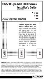
B. View and record low end and high end trim.<br />
1. Press button 5 repeatedly until the<br />
Low End / High End Trim LED lights.<br />
■ Use buttons 1 and 2 to view present settings for<br />
one or both of these options in the Value<br />
display and record the data into the Circuit<br />
Directory.<br />
■ Low end/ high end trim have default settings for<br />
each load type. If the settings were not changed<br />
and match the defaults, it is unnecessary to<br />
record them into the Circuit Directory.<br />
■ Use this chart to compare values and to translate<br />
load type settings (Original Circuit Selector<br />
to Replacement Circuit Selector II settings are<br />
different).<br />
SELECT CIRCUIT<br />
SELECT VALUE DISPLAYED<br />
Load Type<br />
1 Inc/Mag LV<br />
2 Fluorescent<br />
3 Neon/CC<br />
Circuit<br />
VIEW VALUE<br />
SELECT VALUE<br />
Value<br />
Control and Zone Assigned<br />
Using circuit schedule<br />
Using Zone Capture<br />
3<br />
4<br />
5<br />
4 Non-dim<br />
5 Elec. LV<br />
– Unassigned<br />
Low End Trim (optional)<br />
High End Trim (optional)<br />
Circuit Level<br />
TM<br />
1<br />
2<br />
1 2 3 4 D 5<br />
SELECT CIRCUIT<br />
VIEW VALUE<br />
SELECT VALUE<br />
Link A<br />
Link B<br />
Circuit<br />
Value<br />
SELECT VALUE DISPLAYED<br />
Circuit Level<br />
5<br />
Load Type (See Instructions)<br />
Zone Assignment w/ Circuit Schedule<br />
Zone Assignment w/ Zone Capture TM<br />
Low-End Trim<br />
High-End Trim<br />
Address (Ad displayed)<br />
C<br />
1<br />
2<br />
3<br />
4<br />
D<br />
Load Type<br />
Default Settings<br />
1<br />
2<br />
3<br />
8<br />
4<br />
6<br />
5<br />
7<br />
Incandescent<br />
Fluorescent<br />
Not Available<br />
Neon<br />
Not Available<br />
Non-Dim Slider<br />
Non-Dim<br />
Screen Non-Dim<br />
Elect. LV<br />
Included w/ Incandescent<br />
Fan<br />
1-1<br />
2-1<br />
2-2<br />
2-3<br />
2-4<br />
2-5<br />
2-7<br />
3-1<br />
4-1<br />
4-2<br />
4-3<br />
4-4<br />
5-1<br />
6-1<br />
7-1<br />
Incandescent<br />
FDB<br />
Tu-Wire ®<br />
0-10 w/ TVM<br />
PWM w/ TVM<br />
Tridonic ® DSI w/ TVM<br />
DALI 1<br />
Neon<br />
w/ TVM<br />
Non-Dim >0 On<br />
Non-Dim Slider<br />
Last On, First Off<br />
First On, First Off<br />
Elect. LV<br />
Magnetic LV<br />
Fan<br />
1<br />
Intensity broadcast only * Please call <strong>Lutron</strong> Technical Assistance Hotline at 1-800-523-9466.<br />
Low End<br />
Trim<br />
5<br />
28<br />
27<br />
10<br />
10<br />
10<br />
10<br />
24<br />
1<br />
1<br />
1<br />
1<br />
5<br />
5<br />
Custom Code*<br />
High End<br />
Trim<br />
90<br />
81<br />
95<br />
90<br />
90<br />
90<br />
90<br />
68<br />
99<br />
99<br />
99<br />
99<br />
90<br />
90<br />
6
Record Present Data<br />
STEP 2: Record Present Data (cont’d)<br />
C. View and record zone assignments.<br />
1. Press button 5 repeatedly until the Zone<br />
Assignment w/ Circuit Schedule LED lights.<br />
■ Use buttons 1 and 2 to view the present zone<br />
assignments in the Value display and record the data<br />
into the Circuit Directory under the appropriate<br />
column.<br />
Link Status<br />
S ELECT C IRCUIT<br />
Circuit<br />
V IEW V ALUE<br />
S ELECT V ALUE<br />
3<br />
4<br />
Value<br />
Load Type<br />
5<br />
1 Inc/Mag LV 4 Non-dim<br />
2 Fluorescent 5 Elec. LV<br />
3 Neon/CC – Unassigned<br />
S ELECT V ALUE D ISPLAYED<br />
Control and Zone Assigned<br />
Using circuit schedule<br />
Using Zone Capture<br />
Low End Trim (optional)<br />
High End Trim (optional)<br />
Power OK (Pins 1,2)<br />
Data OK (Pins 3,4)<br />
TM<br />
1<br />
2<br />
Common<br />
24VFW<br />
MUX<br />
MUX<br />
Drain<br />
Sense<br />
Comm<br />
Link Link<br />
A B<br />
MUX<br />
MUX<br />
Drain<br />
1 2 3 4 D 5 C D<br />
SELECT CIRCUIT<br />
1<br />
2<br />
Circuit<br />
VIEW VALUE<br />
SELECT VALUE<br />
Link A<br />
3<br />
Link B<br />
4<br />
Value<br />
SELECT VALUE DISPLAYED<br />
Circuit Level<br />
5<br />
Load Type (See Instructions)<br />
Zone Assignment w/ Circuit Schedule<br />
Zone Assignment w/Zone Capture TM<br />
Low-End Trim<br />
High-End Trim<br />
Address ('Ad' displayed)<br />
Warning Read instructions before setting<br />
L d T I t ti h l d t<br />
D. Record normal /emergency switch 6 (SW6) position.<br />
■ View the position of SW6 (located at the base of<br />
each Circuit Selector) and record its setting in the<br />
space provided at the bottom of the Circuit<br />
Directory.<br />
Example: The unit’s setting in this drawing is in<br />
the left position. See the Set Up System section of<br />
the GP <strong>Installation</strong> Guide included with this kit for<br />
details about this switch setting.<br />
E. View and record the address assigned to the Circuit<br />
Selector.<br />
1. Press and hold buttons 2 and 5 until the Select<br />
Value LED flashes once per second (must hold for<br />
about 9 seconds).<br />
2. Press button 5 until the Low End Trim LED lights.<br />
The address number (1-511 range) will appear in<br />
the Value display.<br />
To exit, press and hold buttons 1 and 5 on the Circuit<br />
Selector until the View Value LED lights.<br />
Link Status<br />
SELECT CIRCUIT<br />
SELECT VALUE DISPLAYED<br />
Load Type<br />
1 Inc/Mag LV<br />
2 Fluorescent<br />
3 Neon/CC<br />
Circuit<br />
VIEW VALUE<br />
SELECT VALUE<br />
Value<br />
Control and Zone Assigned<br />
Using circuit schedule<br />
Using Zone Capture<br />
3<br />
4<br />
5<br />
4 Non-dim<br />
5 Elec. LV<br />
– Unassigned<br />
TM<br />
Low End Trim (optional)<br />
High End Trim (optional)<br />
Power OK (Pins 1,2)<br />
Data OK (Pins 3,4)<br />
1<br />
2<br />
2<br />
1<br />
Common<br />
24VFW<br />
MUX<br />
MUX<br />
Drain<br />
Sense<br />
1 2 3 4 D 5 A Link<br />
SELECT CIRCUIT<br />
VIEW VALUE<br />
SELECT VALUE<br />
Link A<br />
Link B<br />
Circuit<br />
Value<br />
B<br />
SELECT VALUE DISPLAYED<br />
Circuit Level<br />
5<br />
Load Type (See Instructions)<br />
Zone Assignment w/ Circuit Schedule<br />
Zone Assignment w/ Zone Capture TM<br />
Low-End Trim<br />
High-End Trim<br />
Address (Ad displayed)<br />
Comm<br />
Link<br />
C<br />
MUX<br />
MUX<br />
1<br />
2<br />
3<br />
4<br />
Drain<br />
D<br />
2<br />
1<br />
Press button 5 until “Ad” is displayed in the Circuit<br />
display. The address number (1-512 range) will appear<br />
in the Value display.<br />
Circuit Level<br />
7
Record Present Data<br />
The PLL (Phase Lock Loop) is a software setting that<br />
helps prevent the lights from flickering. If the existing<br />
dimmers/modules do not have RTISS , the PLL<br />
setting on the Replacement Circuit Selector must be<br />
made to match the PLL setting of the existing Circuit<br />
Selector.<br />
STOP<br />
If this is a GP Panel that was shipped after<br />
July 2000, or all dimmers are being<br />
upgraded, this portion of Step 2 is unnecessary.<br />
These newer dimmers/modules<br />
have been equipped with the Real Time<br />
Illumination Stability System (RTISS ).<br />
STEP 2: Record Present Data (cont’d)<br />
F. View and record the PLL setting.<br />
PLL ON<br />
PLL OFF<br />
1. Turn the system power OFF, then back ON.<br />
Link Status<br />
Power OK (Pins 1,2)<br />
Data OK (Pins 3,4)<br />
Link Status<br />
Power OK (Pins 1,2)<br />
Data OK (Pins 3,4)<br />
■<br />
If only the first zone assignment LED is ON, the<br />
PLL setting is ON.<br />
SELECT CIRCUIT<br />
Circuit<br />
1<br />
2<br />
SELECT CIRCUIT<br />
Circuit<br />
1<br />
2<br />
■<br />
If both zone assignment LEDs are ON, the PLL<br />
setting is OFF.<br />
Record this setting in the space provided at the<br />
bottom of the Circuit Directory.<br />
VIEW VALUE<br />
SELECT VALUE<br />
SELECT VALUE DISPLAYED<br />
Load Type<br />
1 Inc/Mag LV<br />
2 Fluorescent<br />
3 Neon/CC<br />
Value<br />
3<br />
4<br />
5<br />
4 Non-dim<br />
5 Elec. LV<br />
– Unassigned<br />
VIEW VALUE<br />
SELECT VALUE<br />
SELECT VALUE DISPLAYED<br />
Load Type<br />
1 Inc/Mag LV<br />
2 Fluorescent<br />
3 Neon/CC<br />
Value<br />
3<br />
4<br />
5<br />
4 Non-dim<br />
5 Elec. LV<br />
– Unassigned<br />
Control and Zone Assigned<br />
Using circuit schedule<br />
Control and Zone Assigned<br />
Using circuit schedule<br />
Using Zone Capture<br />
TM<br />
Using Zone Capture<br />
TM<br />
Low End Trim (optional)<br />
Low End Trim (optional)<br />
High End Trim (optional)<br />
High End Trim (optional)<br />
Circuit Level<br />
Circuit Level<br />
®<br />
®<br />
1. Press and hold buttons 2 and 5 until the Select<br />
Value LED flashes in intervals of two.<br />
2. Press and hold buttons 1, 2, and 5 (for about<br />
9 seconds) until the Select Value LED flashes in<br />
intervals of three .<br />
3. Press button 5 repeatedly until “PL” appears in the<br />
Value display with either the number 1, 2, or 3 (PLL<br />
ON) or blank space (PLL OFF) next to it. Record this<br />
value in the PLL column of the Circuit Directory.<br />
4. Use buttons 1 and 2 to view and record the PLL<br />
setting for each circuit.<br />
Note: Circuit Selector II may have multiple PLL settings,<br />
so it is necessary to record the value for each<br />
circuit.<br />
5. To exit, press and hold buttons 1 and 5 until the<br />
View Value LED lights.<br />
PLL ON<br />
Common<br />
24VFW<br />
MUX<br />
MUX<br />
Drain<br />
Sense<br />
Link<br />
1 2 3 4 D 5 A Link B C D<br />
SELECT CIRCUIT<br />
1<br />
2<br />
Circuit<br />
VIEW VALUE<br />
1<br />
SELECT VALUE<br />
Link A<br />
Link B<br />
Value<br />
SELECT VALUE DISPLAYED<br />
Circuit Level<br />
5<br />
Load Type (See Instructions)<br />
Zone Assignment w/ Circuit Schedule<br />
Zone Assignment w/ Zone Capture TM<br />
Low-End Trim<br />
High-End Trim<br />
Address (Ad displayed)<br />
Comm<br />
MUX<br />
MUX<br />
3<br />
4<br />
Drain<br />
3<br />
2<br />
PLL OFF<br />
Common<br />
24VFW<br />
MUX<br />
MUX<br />
Drain<br />
Sense<br />
Link<br />
1 2 3 4 D 5 A Link B C D<br />
SELECT CIRCUIT<br />
1<br />
4<br />
2<br />
Circuit<br />
VIEW VALUE<br />
SELECT VALUE<br />
Comm<br />
MUX<br />
MUX<br />
Link A<br />
3<br />
Link B<br />
4<br />
Value<br />
SELECT VALUE DISPLAYED<br />
Circuit Level<br />
5<br />
Load Type (See Instructions)<br />
Zone Assignment w/ Circuit Schedule<br />
Zone Assignment w/ Zone Capture TM<br />
Low-End Trim<br />
High-End Trim<br />
Address (Ad displayed)<br />
Drain<br />
8
Remove Wiring from Existing<br />
Circuit Selector<br />
STEP 3: Remove Wiring from Existing<br />
Circuit Selector<br />
A. Turn control breaker ‘C’ OFF.<br />
OFF<br />
Warning! For GP3, GP4 (breakers provided by<br />
customer), or LP Panel, the input breaker of<br />
Circuit 1 powers the control wiring as well as<br />
Circuit 1's dimmer and load.<br />
C<br />
B. Remove wiring from the existing Circuit Selector.<br />
1. Carefully unplug the Class 2/PELV 24VAC<br />
<strong>Lutron</strong> Wiring with a screwdriver.<br />
Original Circuit Selector<br />
Circuit Selector II<br />
Caution! If the Circuit Selector has two (2)<br />
dimmer links, it is necessary to tag each<br />
link to ensure that they are reattached to the<br />
same outlets at the bottom of the<br />
Replacement Circuit Selector.<br />
2. Remove dimmer link(s) from the bottom of the<br />
Circuit Selector.<br />
9
Remove Wiring from Existing<br />
Circuit Selector<br />
STEP 3: Remove Wiring from Existing<br />
Circuit Selector (cont’d)<br />
3. Unplug the Link A Terminal Block from the<br />
Replacement Circuit Selector.<br />
1 2 3 4 D 5<br />
Link A<br />
Terminal<br />
Block<br />
C<br />
D<br />
Common<br />
24VFW<br />
MUX<br />
Data A OK<br />
MUX<br />
Drain<br />
Sense<br />
1 2 3 4 D 5<br />
SELECT CIRCUIT<br />
A Link<br />
Power<br />
Link<br />
B<br />
Comm<br />
C<br />
MUX<br />
Data B OK<br />
MUX<br />
Drain<br />
D<br />
4.<br />
Move one Control Link wire at a time and insert<br />
each into the corresponding openings of the Link A<br />
Terminal Block of the Replacement Circuit Selector.<br />
Make sure to tighten each terminal’s screw<br />
Unplug the existing Circuit Selector II’s Terminal<br />
Block(s). They will be reattached after the<br />
Replacement Circuit Selector is mounted.<br />
1<br />
2<br />
1 2 3 4 5<br />
Original Circuit<br />
Selector<br />
3<br />
4<br />
5<br />
1<br />
2<br />
1 2 3 4 D 5<br />
3<br />
Replacement<br />
Circuit Selector<br />
4<br />
5<br />
Skip<br />
10
Remove Existing<br />
Circuit Selector: Original<br />
Circuit Selector<br />
STEP 4: Remove Existing Circuit Selector:<br />
Original Circuit Selector<br />
For replacing an Original Circuit Selector:<br />
(See next page for Circuit Selector II)<br />
A. Loosen and remove the two nuts and star washers<br />
from behind the Circuit Selector by turning each<br />
counterclockwise using a 11/32” (9 mm) nut driver.<br />
Save these fasteners to use when mounting the<br />
Replacement Circuit Selector.<br />
Caution! When removing these nuts and star washers,<br />
do not allow them to fall into the panel. Contact with<br />
exposed wiring may cause damage.<br />
B. Remove the Circuit Selector by pulling the unit away<br />
from the side of the panel.<br />
11
Remove Existing Circuit<br />
Selector: Circuit Selector II<br />
STEP 4: Remove Existing Circuit<br />
Selector: Circuit Selector II<br />
For replacing a Circuit Selector II: (See<br />
previous page for Original Circuit Selector)<br />
A. Loosen (but do not remove) the two nuts behind the<br />
Circuit Selector II by turning each counterclockwise<br />
using a 11/32” (9 mm) nut driver.<br />
B. To remove the Circuit Selector II:<br />
1. Lift up,<br />
2. Pull towards the front of the panel.<br />
2<br />
1<br />
12
Mount Replacement<br />
Circuit Selector<br />
STEP 5: Mount Replacement Circuit<br />
Selector<br />
A.<br />
If the star washers and nuts were removed in Step<br />
4, replace them, but do no tighten completely.<br />
B. Mount Replacement Circuit Selector:<br />
1. Slide the Replacement Circuit Selector over the<br />
screw/stud<br />
2. Pull down.<br />
2<br />
1<br />
2. Firmly tighten both nuts and star washers.<br />
13
Rewire Replacement<br />
Circuit Selector<br />
STEP 6:<br />
Rewire Replacement Circuit<br />
Selector<br />
A. Plug Class 2/PELV 24VAC <strong>Lutron</strong> Wiring into the<br />
Replacement Circuit Selector.<br />
B. Plug Terminal Block(s) into the Replacement<br />
Circuit Selector.<br />
1 2 3 4 D 5<br />
Optional<br />
C<br />
D<br />
Data A OK<br />
Power<br />
Data B OK<br />
Common<br />
24VFW<br />
UX<br />
UX<br />
rain<br />
Sense<br />
Link<br />
Link<br />
omm<br />
UX<br />
UX<br />
rain<br />
C. Plug in dimmer link(s) to the corresponding<br />
outlet(s) at the bottom of the Replacement Circuit<br />
Selector.<br />
Caution! When replacing an Original<br />
Circuit Selector for an XP Panel, it is<br />
necessary to put the dimmer link(s) in<br />
upside down (wires should run towards the<br />
top of the Circuit Selector instead of towards<br />
the bottom).<br />
XP Panel Only!<br />
14
CAUTION - Risk of Electric Shock - More than<br />
one disconnect switch may be required to<br />
de-energize the equipment before servicing.<br />
LP-RPM-4U<br />
-120<br />
Listed 243C<br />
Ind. Cont. Eq.<br />
LUTRON R<br />
Coopersburg USA<br />
500-xxxx 1/96<br />
Main Feed:<br />
120VAC<br />
50/60 Hz<br />
Input Current :<br />
16A maximum<br />
Load Current:<br />
16A (TOTAL of<br />
4 loads)<br />
Load Types :<br />
Incandescent,<br />
Magnetic<br />
Low Voltage,<br />
Non-Dim, or<br />
Neon<br />
LED diagnosis:<br />
Slow Blink<br />
=OK, Fast<br />
Blink=No Data<br />
Address<br />
1<br />
8<br />
Switch<br />
Class 2<br />
Control<br />
Harness<br />
Activate Replacement<br />
Circuit Selector<br />
STEP 7:<br />
Activate Replacement Circuit<br />
Selector<br />
A. Turn control breaker ‘C’ ON. ON<br />
Warning! For GP3, GP4 (breakers provided by<br />
customer), or LP Panel, the input breaker of<br />
Circuit 1 powers the control wiring as well as<br />
Circuit 1's dimmer and load.<br />
C<br />
Power OK LED<br />
Data OK LEDs<br />
■ Power OK LED should remain ON, and the Data<br />
OK LED(s) should flash once per second (as long<br />
as that link is active).<br />
1 2 3 4 D 5 C D<br />
Optional Link<br />
Note: If the Power OK LED is not ON, turn OFF<br />
the control breaker, clear the short between wire #2<br />
and #1 (or ground), then reactivate the panel.<br />
Common<br />
24VFW<br />
MUX<br />
Data A OK<br />
MUX<br />
Drain<br />
Sense<br />
Link Link<br />
A B<br />
Power OK<br />
Comm<br />
MUX<br />
Data B OK<br />
MUX<br />
Drain<br />
1 2 3 4 D 5 C D<br />
■ If the dimmer card/ module diagnostic LEDs are all<br />
flashing once per second, skip Step 8 and proceed<br />
to Step 9.<br />
Front View of<br />
Dimmer Card in<br />
GP(JDP) Panel<br />
Front View of<br />
Softswitch Module<br />
in XP Panel<br />
Front View of<br />
Dimming Module<br />
in LP Panel<br />
■ If these LEDs are always ON (GP panels) or in<br />
“Light House” (flashing once every 7 seconds for<br />
XP, LP panels), proceed with Step 8.<br />
LED<br />
XP<br />
D25<br />
079-226<br />
XP Panel Switching Module<br />
Each of four switching circuits rated for:<br />
16A continuous max.<br />
100 through 277VAC 50/60 Hz<br />
1/3 HP at 120VAC, 1/2HP at 277VAC<br />
Listed 243C<br />
Ind. Cont. Eq.<br />
COOPERSBURG, PA 18036 USA<br />
LED<br />
LED<br />
?<br />
For more information, refer<br />
to the Troubleshooting Guide ..........pg. 23<br />
15
Change Baud Rate<br />
The Replacement Circuit Selector is capable of “talking”<br />
to the dimmer/module at various link speeds (baud<br />
rates). The dimmer/module baud rate must match the<br />
slowest “listening” dimmer/module on the link for all<br />
circuits to function.<br />
STOP<br />
If this is a GP Panel that was shipped<br />
after July 2000 or all dimmers are being<br />
upgraded, this portion of Step 8 is<br />
unnecessary.<br />
STEP 8:<br />
Change Baud Rate<br />
1. Press and hold buttons 2 and 5 until the Select<br />
Value LED flashes in intervals of two.<br />
2. Press and hold buttons 1, 2, and 5 (for about 9<br />
seconds) until the Select Value LED flashes in<br />
intervals of three.<br />
Common<br />
24VFW<br />
MUX<br />
MUX<br />
Drain<br />
Sense<br />
Link<br />
1 2 3 4 D 5 A Link B C D<br />
SELECT CIRCUIT<br />
1<br />
2<br />
Circuit<br />
VIEW VALUE<br />
SELECT VALUE<br />
1<br />
Link A<br />
3<br />
Link B<br />
4<br />
Value<br />
SELECT VALUE DISPLAYED<br />
Circuit Level<br />
5<br />
Load Type (See Instructions)<br />
Zone Assignment w/ Circuit Schedule<br />
Zone Assignment w/ Zone Capture TM<br />
Low-End Trim<br />
High-End Trim<br />
Address (Ad displayed)<br />
Comm<br />
MUX<br />
MUX<br />
Drain<br />
2<br />
3. Press button 5 until ‘bd’ appears in the Circuit<br />
display. The Value display will show the current baud<br />
rate.<br />
4. Press button 4 once to lower the baud rate.<br />
5. To exit, press and hold buttons 1 and 5 until the<br />
View Value LED lights.<br />
Note: If the status of the diagnostic LED does not change<br />
(as specified in Step 7), repeat Step 8. If this does<br />
not work, please call <strong>Lutron</strong> Technical Assistance<br />
Hotline at 1-800-523-9466.<br />
Common<br />
24VFW<br />
MUX<br />
MUX<br />
Drain<br />
Sense<br />
1 2 3 4 D 5 A Link<br />
SELECT CIRCUIT<br />
VIEW VALUE<br />
SELECT VALUE<br />
Link A<br />
Link B<br />
Circuit<br />
Value<br />
B<br />
SELECT VALUE DISPLAYED<br />
Circuit Level<br />
5<br />
Load Type (See Instructions)<br />
Zone Assignment w/ Circuit Schedule<br />
Zone Assignment w/ Zone Capture TM<br />
Low-End Trim<br />
High-End Trim<br />
Address (Ad displayed)<br />
Comm<br />
Link<br />
C<br />
MUX<br />
MUX<br />
1<br />
2<br />
3<br />
4<br />
Drain<br />
D<br />
4<br />
3<br />
16
Reenter Settings<br />
STEP 9:<br />
Reenter Settings<br />
A. Reenter PLL settings.<br />
1. Press and hold buttons 2 and 5 until the Select<br />
Value LED flashes in intervals of two.<br />
Common<br />
24VFW<br />
MUX<br />
MUX<br />
Drain<br />
Sense<br />
1 2 3 4 D 5<br />
B<br />
Comm<br />
Link<br />
C<br />
MUX<br />
MUX<br />
Drain<br />
D<br />
Common<br />
24VFW<br />
MUX<br />
MUX<br />
Drain<br />
Sense<br />
1 2 3 4 D 5<br />
B<br />
Comm<br />
Link<br />
C<br />
MUX<br />
MUX<br />
Drain<br />
D<br />
A Link 4<br />
2. Press and hold buttons 1, 2, and 5 (for about 9<br />
seconds) until the Select Value LED flashes in<br />
intervals of three .<br />
3. Press button 5 repeatedly until “PL” appears in the<br />
Value display (PLL OFF).<br />
4. Use buttons 3 and 4 to change the PLL settings for<br />
each circuit (use buttons 1 and 2 to move to different<br />
circuits).<br />
■<br />
If the PLL setting recorded in the Circuit Directory<br />
was ON, it is necessary to reenter the PLL setting<br />
as “PL 1” for each circuit (if the PLL was OFF,<br />
it is unnecessary to change the PLL setting in the<br />
Replacement Circuit Selector).<br />
A Link<br />
SELECT CIRCUIT<br />
1<br />
2<br />
Circuit<br />
VIEW VALUE<br />
1<br />
SELECT VALUE<br />
Link A<br />
Link B<br />
Value<br />
SELECT VALUE DISPLAYED<br />
Circuit Level<br />
5<br />
Load Type (See Instructions)<br />
Zone Assignment w/ Circuit Schedule<br />
Zone Assignment w/ Zone Capture TM<br />
Low-End Trim<br />
High-End Trim<br />
Address (Ad displayed)<br />
3<br />
4<br />
3<br />
2<br />
SELECT CIRCUIT<br />
Circuit<br />
VIEW VALUE<br />
SELECT VALUE<br />
Link A<br />
3<br />
Link B<br />
4<br />
Value<br />
SELECT VALUE DISPLAYED<br />
Circuit Level<br />
5<br />
Load Type (See Instructions)<br />
Zone Assignment w/ Circuit Schedule<br />
Zone Assignment w/ Zone Capture TM<br />
Low-End Trim<br />
High-End Trim<br />
Address (Ad displayed)<br />
1<br />
2<br />
4<br />
■<br />
Enter the PLL settings as recorded in the Circuit<br />
Directory for each circuit (if the PLL setting for<br />
each circuit was “PL”, it is unnecessary to change<br />
the PLL setting in the Replacement Circuit<br />
Selector).<br />
5. To exit, press and hold buttons 1 and 5 until the<br />
View Value LED lights.<br />
To reenter all other settings<br />
recorded in the Circuit Directory,<br />
please refer to the “Start Up<br />
System” section of the GP<br />
<strong>Installation</strong> Guide included with<br />
this kit for complete<br />
instructions.<br />
17
Change Circuit Range<br />
The circuit range is factory set from 1 to 24 (as appears in the Circuit display of the Circuit Selector). It can be set to<br />
accommodate individual panel specifications with settings ranging from 1 to 48 circuits.<br />
If the Replacement Circuit Selector is installed in a panel with 24 or fewer circuits, changing the circuit range is<br />
STOP<br />
not necessary.<br />
Example: If a panel has 7 modules with 4 circuits each (total of 28 circuits), it is necessary to change the circuit range<br />
upper limit to 28.<br />
■ For personal preference, it is possible to change the circuit range to eliminate unused circuits.<br />
Example: Change the circuit range of a GP 8 to 1-8 and eliminate 9-24 (not used).<br />
STEP 10: Change Circuit Range<br />
1. Press and hold buttons 2 and 5 until the Select<br />
Value LED flashes in intervals of two.<br />
2. Press and hold buttons 1, 2, and 5 (for about 9<br />
seconds) until the Select Value LED flashes in<br />
intervals of three.<br />
Common<br />
24VFW<br />
MUX<br />
MUX<br />
Drain<br />
Sense<br />
Link<br />
1 2 3 4 D 5 A Link B C D<br />
SELECT CIRCUIT<br />
1<br />
2<br />
Circuit<br />
VIEW VALUE<br />
SELECT VALUE<br />
1<br />
Comm<br />
MUX<br />
MUX<br />
Drain<br />
Link A<br />
Link B<br />
Value<br />
3<br />
4<br />
2<br />
SELECT VALUE DISPLAYED<br />
Circuit Level<br />
5<br />
Load Type (See Instructions)<br />
Zone Assignment w/ Circuit Schedule<br />
Zone Assignment w/ Zone Capture TM<br />
Low-End Trim<br />
High-End Trim<br />
Address (Ad displayed)<br />
3. Press button 5 repeatedly until ‘rg’ appears in the<br />
Circuit display. The Value display will show the<br />
current upper limit for the circuit range (factory set<br />
at 24).<br />
Common<br />
24VFW<br />
MUX<br />
MUX<br />
Drain<br />
Sense<br />
1 2 3 4 D 5 A Link<br />
SELECT CIRCUIT<br />
Circuit<br />
B<br />
Comm<br />
Link<br />
C<br />
MUX<br />
1<br />
2<br />
MUX<br />
Drain<br />
D<br />
4. Press button 3 to raise the circuit range upper<br />
limit or button 4 to lower the circuit range limit.<br />
5. To exit, press and hold buttons 1 and 5 until<br />
the View Value LED lights.<br />
VIEW VALUE<br />
SELECT VALUE<br />
Link A<br />
Link B<br />
Value<br />
SELECT VALUE DISPLAYED<br />
Circuit Level<br />
5<br />
Load Type (See Instructions)<br />
Zone Assignment w/ Circuit Schedule<br />
Zone Assignment w/ Zone Capture TM<br />
3<br />
4<br />
4<br />
3<br />
5<br />
Low-End Trim<br />
High-End Trim<br />
Address (Ad displayed)<br />
18
Change Circuit Offset<br />
The circuit offset is factory set to 0 (as appears in the Circuit display of the Circuit Selector). It can be set to offset the<br />
1st circuit by a count of 24 or 48.<br />
STOP<br />
The circuit offset is changed generally for GP-36 or GP-72 panels only.<br />
Example: The Circuit display would scroll from 25 to 48 (with a circuit range of 24 - see previous page) when the<br />
circuit offset is switched from 0 to 24.<br />
■ For personal preference, it is possible to change the circuit offset to designate two different panels’ circuit numbers<br />
as unique.<br />
Example: Change the circuit offset of one GP 24 panel to 24 so it displays circuit 25-48, while leaving a<br />
previous GP 24 panel’s circuit offset unchanged to read 1-24.<br />
STEP 11: Change Circuit Offset<br />
1. Press and hold buttons 2 and 5 until the Select<br />
Value LED flashes in intervals of two.<br />
2. Press and hold buttons 1, 2, and 5 (for about 9<br />
seconds) until the Select Value LED flashes in<br />
intervals of three.<br />
Common<br />
24VFW<br />
MUX<br />
MUX<br />
Drain<br />
Sense<br />
Link<br />
1 2 3 4 D 5 A Link B C D<br />
SELECT CIRCUIT<br />
1<br />
2<br />
Circuit<br />
VIEW VALUE<br />
SELECT VALUE<br />
1<br />
Comm<br />
MUX<br />
MUX<br />
Drain<br />
Link A<br />
Link B<br />
Value<br />
3<br />
4<br />
2<br />
SELECT VALUE DISPLAYED<br />
Circuit Level<br />
5<br />
Load Type (See Instructions)<br />
Zone Assignment w/ Circuit Schedule<br />
Zone Assignment w/ Zone Capture TM<br />
Low-End Trim<br />
High-End Trim<br />
Address (Ad displayed)<br />
3. Press button 5 repeatedly until ‘oF’ appears in the<br />
Circuit display. The Value display will show the<br />
current setting for the circuit offset (factory set at<br />
0).<br />
Common<br />
24VFW<br />
MUX<br />
MUX<br />
Drain<br />
Sense<br />
1 2 3 4 D 5 A Link<br />
SELECT CIRCUIT<br />
Circuit<br />
B<br />
Comm<br />
Link<br />
C<br />
MUX<br />
1<br />
2<br />
MUX<br />
Drain<br />
D<br />
4. Press button 3 to raise the circuit offset or button<br />
4 to lower the circuit offset.<br />
5. To exit, press and hold buttons 1 and 5 until<br />
the View Value LED lights.<br />
VIEW VALUE<br />
SELECT VALUE<br />
Link A<br />
Link B<br />
Value<br />
SELECT VALUE DISPLAYED<br />
Circuit Level<br />
5<br />
Load Type (See Instructions)<br />
Zone Assignment w/ Circuit Schedule<br />
Zone Assignment w/ Zone Capture TM<br />
3<br />
4<br />
4<br />
3<br />
5<br />
Low-End Trim<br />
High-End Trim<br />
Address (Ad displayed)<br />
19
Circuit Directory<br />
Primary Zone<br />
Secondary Zone<br />
(only with 2Link )<br />
Circuit 1<br />
Load Type 2<br />
Low<br />
End<br />
Trim<br />
High<br />
End<br />
Trim<br />
Zone<br />
Assignment<br />
Link A<br />
or B<br />
Zone<br />
Assignment<br />
Link A<br />
or B<br />
Hierarchy<br />
Zone X (A2<br />
or b2 only)<br />
PLL<br />
1<br />
2<br />
3<br />
4<br />
5<br />
6<br />
7<br />
8<br />
9<br />
10<br />
11<br />
12<br />
13<br />
14<br />
15<br />
16<br />
17<br />
18<br />
19<br />
20<br />
21<br />
22<br />
23<br />
24<br />
1<br />
If replacing a 48-Zone Circuit Selector, make a copy of this chart and re-number the Circuit column 25-48.<br />
2<br />
Load Type settings are different for the Original Circuit Selector and the Circuit Selector II. See the chart on page 6 for the updated<br />
settings when reentering information.<br />
Switch 6<br />
20<br />
(LEFT, CENTER, or RIGHT)<br />
Address<br />
PLL
Other Functions<br />
The following functions have all been set to factory default<br />
for standard operation; any changes are optional.<br />
?<br />
Need more information? Call <strong>Lutron</strong> to find out more<br />
about these and other Circuit Selector functions.<br />
Chicago Setting-<br />
Override Setting-<br />
Sets a “floor” which the dimmer will not go below. This function is used<br />
for emergency circuits in situations where the lights are not allowed to<br />
turn off, such as in Chicago.<br />
Allows circuit(s) connected to an emergency panel to enter an intensity<br />
other than full (100%).<br />
Programmed OFF Level-<br />
Allows a dimmer to enter a specific intensity other than zero (0) when a<br />
dimmer’s intensity command is 0%.<br />
Warning! Defeating <strong>Lutron</strong>’s “Airgap OFF” feature must be carefully<br />
considered for safety reasons.<br />
“SL” Slushing-<br />
Allows for modification of a dimmer’s intensity change response time. An<br />
intensity change can have a “jump to” response or one of three “smooth<br />
out the transition” responses.<br />
“SF” Soft Start-<br />
“UC” Voltage Compensation-<br />
Allows the standard transition from OFF to ON to be defeated. It is<br />
recommended that the default settings for each load type<br />
remain unchanged.<br />
Allows the standard compensation for voltage changes to be defeated. It<br />
is recommended that the default settings for each load type<br />
remain unchanged.<br />
“AU” Autodetect-<br />
Allows the protocol of each control link to be autodetected (default) or<br />
manually assigned (OFF). This function is changed to OFF primarily if the<br />
control has not been installed but needs to be programmed beforehand to<br />
autodetect, or if the Circuit Selector has trouble detecting DMX 512<br />
protocol.<br />
21
LP-RPM-4U<br />
-120<br />
Listed 243C<br />
Ind. Cont. Eq.<br />
500-xxxx<br />
LUTRON R<br />
Coopersburg USA<br />
Main Feed:<br />
120VAC<br />
50/60 Hz<br />
Input Current :<br />
16A maximum<br />
Load Current:<br />
16A (TOTAL of<br />
4 loads)<br />
Load Types :<br />
Incandescent,<br />
Magnetic<br />
Low Voltage,<br />
Non-Dim, or<br />
Neon<br />
LED diagnosis:<br />
Slow Blink<br />
=OK, Fast<br />
Blink=No Data<br />
Address<br />
1<br />
8<br />
Switch<br />
Class 2<br />
Control<br />
Harness<br />
1/96<br />
D25<br />
079-226<br />
Each of four switching circuits rated for:<br />
16A continuous max.<br />
100 through 277VAC 50/60 Hz<br />
1/3 HP at 120VAC, 1/2HP at 277VAC<br />
CAUTION - Risk of Electric Shock - More than<br />
one disconnect switch may be required to<br />
de-energize the equipment before servicing.<br />
Listed 243C<br />
Ind. Cont. Eq.<br />
COOPERSBURG, PA 18036 USA<br />
LUTRON<br />
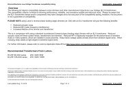
Troubleshooting<br />
Guide<br />
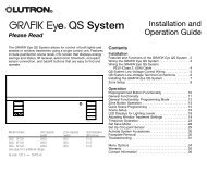
Troubleshooting Guide<br />
XP<br />
XP Panel Switching Module<br />
<strong>RK</strong>-<strong>CS</strong> Diagnostics<br />
Symptom<br />
None -<br />
Normal<br />
operation<br />
(as reference)<br />
Dimmer<br />
Card LED<br />
“Heartbeat”<br />
(~1 per sec)<br />
LP/ELV Module<br />
LED<br />
“Heartbeat”<br />
(~1 per sec)<br />
XP/XP2<br />
Module LED<br />
“Heartbeat”<br />
(~1 per sec)<br />
‘Power<br />
OK’ LED<br />
On<br />
‘Data OK’<br />
LED<br />
“Heartbeat”<br />
(~1 per sec)<br />
Circuit #<br />
Display<br />
OK<br />
Out<br />
GRX LEDs<br />
OK<br />
OK<br />
Possible Cause/Solutions<br />
All LEDs show OK,<br />
see below for other suggestions.<br />
Push any button on Circuit Selector<br />
(display turns off in 20 minutes).<br />
"LC"<br />
OK<br />
<strong>RK</strong>-<strong>CS</strong> locked out - contact <strong>Lutron</strong>.<br />
All dimmers<br />
controlled by<br />
1st zone<br />
“Heartbeat”<br />
(~1 per sec)<br />
“Heartbeat”<br />
(~1 per sec)<br />
“Heartbeat”<br />
(~1 per sec)<br />
On<br />
“Heartbeat”<br />
(~1 per sec)<br />
OK<br />
OK<br />
<strong>RK</strong>-<strong>CS</strong> not set up - see instructions for<br />
Zone Assignment.<br />
All outputs On<br />
FULL or Off<br />
only<br />
“Heartbeat”<br />
(~1 per sec)<br />
“Heartbeat”<br />
(~1 per sec)<br />
“Heartbeat”<br />
(~1 per sec)<br />
On<br />
“Heartbeat”<br />
(~1 per sec)<br />
OK<br />
OK<br />
XP panels only switch On or Off<br />
(no dimming).<br />
<strong>RK</strong>-<strong>CS</strong> not set up - see instructions for<br />
Load Types.<br />
No dimming -<br />
always FULL<br />
“Flutter”*<br />
(~5 per sec)<br />
“Flutter”*<br />
(~5 per sec)<br />
“Flutter”*<br />
(~5 per sec)<br />
On<br />
“Heartbeat”<br />
(~1 per sec)<br />
OK<br />
OK<br />
Dimmer in Bypass - see instructions on<br />
load wiring.<br />
Dimmer defective - contact <strong>Lutron</strong>.<br />
“Light House”<br />
(~1 per 7 sec)<br />
“Light House”<br />
(~1 per 7 sec)<br />
“Light House”<br />
(~1 per 7 sec)<br />
On<br />
“Heartbeat”<br />
(~1 per sec)<br />
OK<br />
OK<br />
2-pin plug(s) for dimmer communication<br />
link not connected at the bottom of<br />
the <strong>RK</strong>-<strong>CS</strong>.<br />
No dimming -<br />
Lights stuck at<br />
present light<br />
level/“frozen”<br />
“Light House”<br />
(~1 per 7 sec)<br />
“Light House”<br />
(~1 per 7 sec)<br />
“Light House”<br />
(~1 per 7 sec)<br />
Off<br />
Off<br />
Out<br />
Off<br />
Control breaker “C” Off.<br />
2 power plugs at top of <strong>RK</strong>-<strong>CS</strong> not<br />
connected.<br />
Control transformer may be damaged.<br />
“Light House”<br />
(~1 per 7 sec)<br />
All ON<br />
continuously<br />
“Light House”<br />
(~1 per 7 sec)<br />
“Light House”<br />
(~1 per 7 sec)<br />
“Light House”<br />
(~1 per 7 sec)<br />
“Light House”<br />
(~1 per 7 sec)<br />
On<br />
On<br />
“Flutter”<br />
(~5 per sec)<br />
N/A<br />
OK<br />
OK<br />
OK<br />
OK<br />
Miswire of control link wiring - wires 3<br />
and 4 may be swapped, shorted to<br />
ground, or open.<br />
Wrong Baud Rate - see section on<br />
Baud Rate.<br />
“Light House”<br />
(~1 per 7 sec)<br />
“Light House”<br />
(~1 per 7 sec)<br />
“Light House”<br />
(~1 per 7 sec)<br />
On<br />
Off<br />
OK<br />
Off<br />
Miswire of control link wiring -<br />
unplugged<br />
terminal block or open wire 1 or 2.<br />
Controls not<br />
working/“Dead”<br />
“Light House”<br />
(~1 per 7 sec)<br />
“Light House”<br />
(~1 per 7 sec)<br />
“Light House”<br />
(~1 per 7 sec)<br />
“Light House”<br />
(~1 per 7 sec)<br />
“Light House”<br />
(~1 per 7 sec)<br />
“Light House”<br />
(~1 per 7 sec)<br />
On<br />
Off<br />
Off<br />
Off<br />
OK<br />
Out<br />
OK<br />
Off<br />
Miswire of control link wiring - open<br />
wire 3 and/or 4.<br />
Miswire of control link wiring - wires 1<br />
and 2 shorted together or wire 2<br />
shorted to ground. Turn control breaker<br />
“C” Off a minimum of 30 sec., clear the<br />
short, then turn breaker back On.<br />
<strong>RK</strong>-<strong>CS</strong> does<br />
not function the<br />
same as<br />
previous Circuit<br />
Selector<br />
“Heartbeat”<br />
(~1 per sec)<br />
“Heartbeat”<br />
(~1 per sec)<br />
“Heartbeat”<br />
(~1 per sec)<br />
On<br />
“Heartbeat”<br />
(~1 per sec)<br />
OK<br />
OK<br />
Contact <strong>Lutron</strong> with job # (ex. 21022-<br />
01) and description of function desired.<br />
* An accurate “Flutter” rate requires that the circuit be cycled OFF, then ON to high end from the appropriate Control Unit.<br />
22
Internet: www.lutron.com<br />
E-mail: product@lutron.com<br />
WORLD HEADQUARTERS<br />
<strong>Lutron</strong> Electronics Co. Inc.,<br />
TOLL FREE: (800) 523-9466<br />
(U.S.A., Canada, Caribbean)<br />
Tel: (610) 282-3800;<br />
International 1- 610-282-3800<br />
Fax: (610) 282-3090;<br />
International 1-610-282-3090<br />
GREAT BRITAIN<br />
<strong>Lutron</strong> EA Ltd.,<br />
Tel: (171) 702-0657;<br />
International 44-207-702-0657<br />
Fax: (171) 480-6899;<br />
International 44-207-480-6899<br />
GERMANY<br />
<strong>Lutron</strong> Electronics GmbH<br />
Tel: (309) 710-4590;<br />
International 49 309 710-4590<br />
Fax: (309) 710-4591;<br />
International 49 309 710-4591<br />
ASIAN HEADQUARTERS<br />
<strong>Lutron</strong> Asuka Corporation (Japan)<br />
Tel: (03) 5405-7333;<br />
International 81-3-5405-7333<br />
Fax: (03) 5405-7496;<br />
International 81-3-5405-7496<br />
HONG KONG SALES OFFICE<br />
<strong>Lutron</strong> GL (Hong Kong)<br />
Tel: 2104-7733;<br />
International 852-2104-7733<br />
Fax: 2104-7633;<br />
International 852-2104-7633<br />
SINGAPORE<br />
<strong>Lutron</strong> GL (Singapore)<br />
Tel: 65 220 4666<br />
Fax: 65 220 4333<br />
LIMITED WARRANTY<br />
<strong>Lutron</strong> will, at its option, repair or replace any unit that is defective in<br />
materials or manufacture within one year after purchase. For warranty service,<br />
return unit to place of purchase or mail to <strong>Lutron</strong> at 7200 Suter Rd.,<br />
Coopersburg, PA 18036-1299, postage pre-paid.<br />
This warranty is in lieu of all other express warranties, and the<br />
implied warranty of merchantability is limited to one year from<br />
purchase. This warranty does not cover the cost of installation,<br />
removal or re-installation, or damage resulting from misuse,<br />
abuse, or improper or incorrect repair, or damage from<br />
improper wiring or installation. This warranty does not cover<br />
incidental or consequential damages. <strong>Lutron</strong>’s liability on any<br />
claim for damages arising out of or in connection with the<br />
manufacture, sale, installation, delivery, or use of the unit<br />
shall never exceed the purchase price of the unit.<br />
This warranty gives you specific legal rights, and you may also have other<br />
rights which vary from state to state. Some states do not allow limitations<br />
on how long an implied warranty lasts, so the above limitation may not<br />
apply to you. Some states do not allow the exclusion or limitation of incidental<br />
or consequential damages, so the above limitation or exclusion may<br />
not apply to you.<br />
This product may be covered under one or more of the following U.S.<br />
patents: 5,038,081; 5,309,068; 5,530,322; 5,633,540; 5,990,635;<br />
6,046,550; and 6,091,205, and corresponding foreign patents.<br />
<strong>Lutron</strong> , Tu-Wire, GRAFIK <strong>Eye</strong>, and GRAFIK 6000 are registered trademarks,<br />
and GRAFIK 5000, Liaison, Softswitch, 2Link, RTISS and HomeWorks<br />
Interactive are trademarks of <strong>Lutron</strong> Electronics Co., Inc.<br />
Tridonic is a registered trademark of Zumtobel AG.<br />
© 2001 <strong>Lutron</strong> Electronics Co., Inc.<br />
<strong>Lutron</strong> Electronics Co., Inc.<br />
Made and printed in U.S.A.<br />
P/N 030-690 Rev. B 8/01