030913a MW-PS install new.qxp - Lutron Lighting Installation ...
030913a MW-PS install new.qxp - Lutron Lighting Installation ...
030913a MW-PS install new.qxp - Lutron Lighting Installation ...

Create successful ePaper yourself
Turn your PDF publications into a flip-book with our unique Google optimized e-Paper software.
Junction Box Mounted<br />
<strong>Lighting</strong>Controller<br />
Coopersburg, PA18036<br />
Unoccupied<br />
Light Level<br />
microWATT<br />
powered<br />
when lit<br />
OFF + – +<br />
Dimming Range<br />
MIN MAX<br />
1 2 3 4 5 6 7 8 9 10 11 12 13 14 15 16<br />
Occupant<br />
Sensor<br />
FUNCTION INDICA<br />
Ballast<br />
Control<br />
Wall<br />
Control<br />
Photo<br />
Sensor<br />
LISTED<br />
Energy<br />
Management<br />
Equipment<br />
5C81<br />
TOR OPERATION (See <strong>install</strong>ation guide for more details)<br />
Off - microWATT is in Normal Operation Mode<br />
Slow Blinking - microWATT is in Override Mode<br />
On - microWATT is in 100hr Lamp Burn-in Mode (Depress the Lamp Burn-in<br />
Activation Button to Return to Normal Operation Mode)<br />
Daylight<br />
Comp.<br />
– + – +<br />
1 2 3 4 5 6 7 8 9 10 11 12 13 14 15 16<br />
CLA S 2 LOW VOLTAGE WIRING<br />
Function<br />
Indicator<br />
Lamp<br />
Burn-in<br />
P/N 500-8766 Rev. A<br />
R<br />
Coopersburg, PA 18036 USA<br />
D<strong>MW</strong>-LZC1<br />
<strong>Lighting</strong> Zone Controller<br />
Controlador de zona de luz<br />
Contrôleur de zone d'Éclairage<br />
For <strong>install</strong>ation, refer to<br />
the Digital microWATT<br />
Hardware Installer's<br />
Guide (p/n 031-268).<br />
+24V<br />
Para la instalación,<br />
consulte la Guía del<br />
Instalador de Digital<br />
microWATT Hardware<br />
(p/n 031-268).<br />
+24V<br />
+15V<br />
CLASS 2 LOW VOL TAGE WIRING<br />
Digital Link<br />
Enlace Digital<br />
Lien Digital<br />
1 2 3 4 5 6 7 8 9 10 11 12 13 14 15<br />
P/N 500-9066 Rev. F<br />
Pour <strong>install</strong>ation, référer au<br />
guide pour quincaillerie<br />
Digital microWATT<br />
(p/n 031-268) de<br />
l'<strong>install</strong>ateur.<br />
TEL<br />
FAX<br />
USA, Canada 1-800-523-9466 1-610-282-0298 www.lutron.com<br />
Mexico 1-888-235-2910 1-610-282-1243 www.lutron.com<br />
LUTRON<br />
MUX<br />
MUX<br />
TM<br />
Radio FrequencyController<br />
Coopersburg, PA 18036<br />
RECEIVER SWITCHSETTINGS<br />
1. UP-Prese t Lock DN.-Preset Adj.<br />
2. UP-Occ. Sensor DN.-Emerg. Set.<br />
3. UP-FDB Mode DN.-ECO Mode<br />
4. UP-OF DN.-Min. Light<br />
5. UP-Auto ON DN.-Manual ON<br />
See Installers Guide for System<br />
Addressing and Programming Instructions<br />
Receiver<br />
Settings<br />
1 2 3 4 5<br />
Powered<br />
When Lit<br />
1 2 3 4 5 Power Status Program 1 2 3<br />
Burn-In<br />
Shield<br />
1 2 3 4 5 6 7 8 9 10 11 12 13 14 15 16<br />
CLASS2 LOW VOLTAGE WIRING<br />
l 1<br />
R<br />
l 2<br />
LISTED243C<br />
Ind. Cont.Eq.<br />
1 2 3 4 5 6 7 8 9 10 11 12 13 14 15 16<br />
15V<br />
24V<br />
Status<br />
Indicator<br />
STATUSINDICATOR OPERATION<br />
ON - Burn-in Mode<br />
Slow Blink -Normal Operation Mode<br />
Fast Blink - Program Mode<br />
Very Fast Blink - Receiving RFData<br />
SHADE SWITCH SETT INGS<br />
1. UP-A/C Shades DN.-Normal Oper.<br />
Program<br />
Buton<br />
Shade<br />
Settings<br />
1 2 3<br />
Occ. Sensor 0-10 V Shade Switch Closures<br />
Burn-in<br />
Buton<br />
®<br />
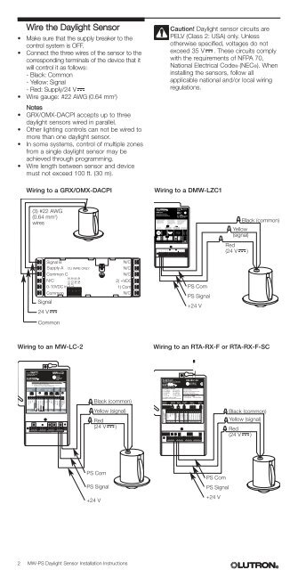
Wire the Daylight Sensor<br />
• Make sure that the supply breaker to the<br />
control system is OFF.<br />
• Connect the three wires of the sensor to the<br />
corresponding terminals of the device that it<br />
will control it as follows:<br />
- Black: Common<br />
- Yellow: Signal<br />
- Red: Supply/24 V<br />
• Wire gauge: #22 AWG (0.64 mm 2 )<br />
Notes<br />
• GRX/OMX-DACPI accepts up to three<br />
daylight sensors wired in parallel.<br />
• Other lighting controls can not be wired to<br />
more than one daylight sensor.<br />
• In some systems, control of multiple zones<br />
from a single daylight sensor may be<br />
achieved through programming.<br />
• Wire length between sensor and device<br />
must not exceed 100 ft. (30 m).<br />
Wiring to a GRX/OMX-DACPI<br />
Caution! Daylight sensor circuits are<br />
PELV (Class 2: USA) only. Unless<br />
otherwise specified, voltages do not<br />
exceed 35 V . These circuits comply<br />
with the requirements of NFPA 70,<br />
National Electrical Code® (NEC®). When<br />
<strong>install</strong>ing the sensors, follow all<br />
applicable national and/or local wiring<br />
regulations.<br />
Wiring to a D<strong>MW</strong>-LZC1<br />
(3) #22 AWG<br />
(0.64 mm 2 )<br />
wires<br />
<strong>PS</strong> Signal<br />
<strong>PS</strong> Com<br />
Circuit Com<br />
WC Com<br />
WC Signal<br />
OCC Signal<br />
OCC Com<br />
Link Com<br />
EMERG<br />
Black (common)<br />
Yellow<br />
(signal)<br />
Red<br />
(24 V )<br />
Signal B<br />
Supply A CU WIRE ONLY<br />
Common C<br />
Signal<br />
24 V<br />
N/C<br />
0-10VDC in<br />
Common<br />
4) IN<br />
3) IN<br />
4) OUT<br />
3) OUT<br />
N/C<br />
N/C<br />
N/C<br />
2) +VDC<br />
1) Com<br />
N/C<br />
<strong>PS</strong> Com<br />
<strong>PS</strong> Signal<br />
+24 V<br />
Common<br />
Wiring to an <strong>MW</strong>-LC-2<br />
Wiring to an RTA-RX-F or RTA-RX-F-SC<br />
® <strong>MW</strong>-LC-2<br />
RadioTouch<br />
RTA-RX-F-SC<br />
Common<br />
Signal<br />
15V<br />
24V<br />
Emergency ON<br />
Timeclock OFF<br />
Common<br />
Load Shed<br />
+ Purple<br />
– Gray<br />
20V<br />
Signal<br />
Common<br />
24V (1)<br />
Signal (2)<br />
Common (3)<br />
100hr Burn-in<br />
Activation<br />
Button<br />
Black (common)<br />
Yellow (signal)<br />
Red<br />
(24 V )<br />
Terminal connections<br />
are Clas 2.<br />
Occ.Com<br />
Signal<br />
<strong>PS</strong> Signal<br />
Circuit Com<br />
0-10 Purple<br />
0-10 Gray<br />
Sivoia Cntr<br />
Sivoia Cntr<br />
Sw Closure 1<br />
Sw Closure 2<br />
Sw Closure 3<br />
Sw Closure 4<br />
Sw Closure 5<br />
Closure Com<br />
© 2000-2002 <strong>Lutron</strong> Electronics Co., Inc.<br />
Black (common)<br />
Yellow (signal)<br />
Red<br />
(24 V )<br />
<strong>PS</strong> Com<br />
<strong>PS</strong> Com<br />
<strong>PS</strong> Signal<br />
<strong>PS</strong> Signal<br />
+24 V<br />
+24 V<br />
2 <strong>MW</strong>-<strong>PS</strong> Daylight Sensor <strong>Installation</strong> Instructions<br />
R