Wiring Diagram of 6A - Lextreme.com
Wiring Diagram of 6A - Lextreme.com
Wiring Diagram of 6A - Lextreme.com

Create successful ePaper yourself
Turn your PDF publications into a flip-book with our unique Google optimized e-Paper software.
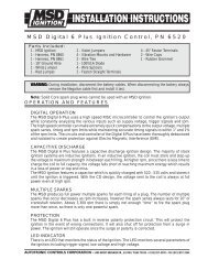
INSTALLATION INSTRUCTIONS 5<br />
Grounds: A poor ground connection can cause many frustrating problems. When a wire is<br />
specified to go to ground, it should be connected to the battery negative terminal, engine<br />
block or chassis. There should always be a ground strap between the engine and the<br />
chassis. Always securely connect the ground wire to a clean, paint free metal surface.<br />
Ballast Resistor: If your vehicle has a ballast resistor in line with the coil wiring, it is not<br />
necessary to bypass it. This is because the MSD receives its main power directly from the<br />
battery.<br />
ROUTING WIRES<br />
The MSD wires should be routed away from direct heat sources such as exhaust manifolds<br />
and headers and any sharp edges. The trigger wires should be routed separate from the<br />
other wires and spark plug wires. It is best if they are routed along a ground plane such as<br />
the block or firewall which creates an electrical shield. The magnetic pickup wires should<br />
always be routed separately and should be twisted together to help reduce extraneous<br />
interference.<br />
WIRE FUNCTIONS<br />
Power Leads<br />
Heavy Red<br />
Heavy Black<br />
Red<br />
Orange<br />
Black<br />
Trigger<br />
Wires<br />
White<br />
Violet<br />
and Green<br />
(Magnetic<br />
Pickup<br />
Connector)<br />
These are the two heavy gauge wires (12 gauge) and are<br />
responsible for getting direct battery voltage to the Ignition. The<br />
ignition has an internal fuse so no fuse is necessary.<br />
This wire connects directly to the battery positive (+) terminal or to<br />
a positive battery junction or the positive side <strong>of</strong> the starter solenoid.<br />
Note: Never connect the alternator.<br />
This wire connects to a good ground, either at the battery negative<br />
(-) terminal or to the engine.<br />
Connects to a switched 12 volt source. Such as the ignition key or switch.<br />
Connects to the positive (+) terminal <strong>of</strong> the coil.<br />
This is the only wire that makes electrical contact with the coil<br />
positive terminal.<br />
Connects to the negative (-) terminal <strong>of</strong> the coil.<br />
This is the only wire that makes electrical contact with the coil<br />
negative terminal.<br />
There are two circuits that can be used to trigger the MSD Ignition;<br />
a Points circuit (White wire) and a Magnetic Pickup circuit (Violet<br />
and Green wires). The two circuits will never be used together.<br />
This wire is used to connect to the points, electronic ignition<br />
amplifier output or to the Yellow wire <strong>of</strong> an MSD Timing Accessory.<br />
When this wire is used, the Magnetic Pickup connector is not used.<br />
These wires are routed together in one harness to form the Magnetic<br />
Pickup connector. The connector plugs directly into an MSD<br />
Distributor or Crank Trigger. It will also connect to factory magnetic<br />
pickups or other aftermarket pickups. The Violet wire is positive (+)<br />
and the Green is negative (-). When these wires are used, the White<br />
wire is not.<br />
AUTOTRONIC CONTROLS CORPORATION • 1490 HENRY BRENNAN DR., EL PASO, TEXAS 79936 • (915) 857-5200 • FAX (915) 857-3344