
Create successful ePaper yourself
Turn your PDF publications into a flip-book with our unique Google optimized e-Paper software.
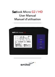
Thank You for purchasing the <strong>Emitor</strong> AB <strong>Satlook</strong> <strong>Color</strong> <strong>HD</strong> instrument.<br />
This manual covers the operation and maintenance of the <strong>Emitor</strong> AB <strong>Satlook</strong><br />
<strong>Color</strong> <strong>HD</strong> instrument used for satellite dish alignment and signal analysis.<br />
All information in this publication is based on the latest product information<br />
available at the time of printing.<br />
<strong>Emitor</strong> AB reserves the right to make changes at any time without notice and<br />
without incurring any obligation.<br />
No part of this publication may be reproduced without written permission.<br />
This manual should be considered a permanent part of the instrument and<br />
should remain with it if the instrument is resold.<br />
If a problem should arise, or if you have any questions about the instrument,<br />
consult an authorized <strong>Emitor</strong> AB dealer.<br />
Notice<br />
Operating the <strong>Satlook</strong> <strong>Color</strong> <strong>HD</strong> instrument requires special skills. Please<br />
read this User Manual thoroughly before operating the instrument.<br />
2<br />
Updated: September 5, 2010
Contents<br />
Overview 3<br />
Unpacking 6<br />
Operating Controls 6<br />
LCD 8<br />
Remote Control 9<br />
Basic Spectrum Operation 10<br />
Basic Digital Mode 12<br />
Digital Mode Functions 13<br />
Digital Picture Mode 14<br />
Analog Picture Mode 16<br />
Memory 17<br />
Text Editor 17<br />
DiSEqC 18<br />
Setup 19<br />
Special Functions 20<br />
UniCable LNB Functions 22<br />
Appendix A – Universal LNB Primer 23<br />
Appendix B – DiSEqC Primer 24<br />
Appendix C – DVB-S and DVB-S2 Primer 26<br />
Appendix D – UniCable Primer 27<br />
Appendix E – Maintenance 29<br />
Appendix F – Specifications 30<br />
Glossary 31<br />
3
Overview<br />
The <strong>Emitor</strong> <strong>Satlook</strong> <strong>Color</strong> <strong>HD</strong> is a Swedish designed spectrum analyzer and satellite<br />
television measuring instrument. The <strong>Satlook</strong> <strong>Color</strong> <strong>HD</strong> was engineered for the precision<br />
alignment and adjustment of satellite dishes.<br />
This instrument was designed for the professional when accurate and precise information<br />
is needed. With ease of operation through powerful processor technology, basic<br />
operation is achieved with only a few controls. The functions are easy to access and only<br />
take minutes to learn. Many functions can be controlled by the enclosed Remote<br />
control.<br />
A 5 inch 16:9 color TFT-LCD display is provided which shows either normal “Free to air”<br />
satellite TV channels in Analog or DVB-S, the frequency spectrum 950-2150 MHz or a<br />
Constellation diagram and digital information regarding the signal.<br />
Menus and help displays are shown on the LCD screen (64x128) beside the monitor and a<br />
keypad is used for the function selection. The knob is used for frequency and other<br />
operations. A remote control is provided which allows most of the commands to be used.<br />
The Spectrum Mode enables the measurement of the satellite spectrum in resolution<br />
steps of 1 MHz to 10 MHz making it easy for the skilled installer to know what satellite<br />
he is receiving and make more detailed measurements. The Spectrum function spans the<br />
frequency band 920-2150 MHz and can be expanded from 4 MHz down to 1 MHz steps.<br />
Cross polarization at a frequency can be easily checked with the cross polarization<br />
function. The instrument has high resolution for accuracy. It presents measured data ±2<br />
dB (at 20 o C). Frequency tuning is done with the main knob in frequency steps between 4<br />
MHz and 1 MHz depending on the span of the spectrum. When the spectrum is<br />
displayed, Automatic Spectrum Identification is provided by accessing the NIT<br />
information by hunting for a DVB-S signal from one of the transponders.<br />
The Analog Picture mode can display a multistandard PAL, NTSC and SECAM picture and<br />
accepts audio frequencies between 5.5 . 8.5 MHz. Analog pictures can be viewed either<br />
directly using the spectrum as a guide, or recalled from 100 user defined memory<br />
positions.<br />
The Digital Mode shows extended information of Modulation, SIG, SNR, BER, MER, and a<br />
constellation diagram. The Satellite Name and position are shown using the Network<br />
Information Table in the MPEG transport stream. Channel detail (or Service Information)<br />
can also be displayed for a transponder if needed.<br />
The user memory positions can save spectrum displays, analog channels, digital channels<br />
and Saved spectrum positions can be mixed simultaneously with an actual reading for<br />
easy comparison and control of signal-levels. Measurements on group of channels can<br />
be made with up to 10 frequencies simultaneously with automatic polarization and band<br />
selection.<br />
For Universal LNBs, the polarisation V/H is switchable by 13/18V and Lo/Hi band with 22<br />
kHz-tone.<br />
4
The instrument features circuitry protection to prevent short circuits during connection<br />
of the LNB.<br />
The DiSEqC function controls all DiSEqC accessories such as switches and positioners.<br />
The <strong>Satlook</strong> <strong>Color</strong> <strong>HD</strong> is powered by a built- in, rechargeable Li-Ion battery. The battery<br />
can be recharged using either the included external battery charger or the car-adaptor.<br />
The <strong>Satlook</strong> <strong>Color</strong> <strong>HD</strong> weighs less than 3kg including the battery and the carrying case.<br />
5
Unpacking<br />
Unpack the instrument and check that the following items are included:<br />
1. <strong>Satlook</strong> <strong>Color</strong> <strong>HD</strong> instrument.<br />
2. Nylon carrying case with shoulder strap.<br />
3. Power supply and charger 110-230VAC /14 VDC, center pin positive<br />
4. Auto Adapter cord (Car charger) 12V.<br />
Operating Controls<br />
The side view of the <strong>Satlook</strong> <strong>Color</strong> <strong>HD</strong> is shown below with the operating<br />
controls indicated.<br />
RS232<br />
Video and<br />
Audio Output<br />
RF Input<br />
from LNB<br />
Keypad<br />
Tuning Knob<br />
Audio Volume<br />
and Tuning<br />
Power<br />
Switch<br />
Charger<br />
Power input<br />
from charger<br />
Power Switch) On battery power, this turns the instrument on and off. When the charger<br />
is connected, the instrument will charge with the switch off, and operate when on. The<br />
instrument will not charge when operating.<br />
Charger Power Input) The instrument can be charged or operated using either the<br />
supplied 14V power supply or from a 12V car cigarette lighter plug using the supplied<br />
connector.<br />
Keypad) This is used to select most of the functions from the menu.<br />
6
RF Input from LNB) This is the LNB input. It supplies 13V/18V and the 22kHz signal<br />
when required.<br />
Audio Volume) The audio volume can be adjusted for either the Digital or Analog<br />
reception.<br />
Audio Tuning) This can tune the Audio passband from 5.5 MHz to 8.5 MHz for Analog TV<br />
reception.<br />
Tuning Knob) This knob is used for frequency selection and other functions. The knob<br />
includes a push button that is used for selection. In the Spectrum mode, the tuning knob<br />
is used for frequency adjustments, bandwidth (span) adjustments and signal Offset level.<br />
The knob button is used to change the mode. In the Digital Picture mode, the knob is<br />
used to select the next picture, and for memory selections. In the Analog Picture mode,<br />
the knob is used for frequency selection and for memory locations. In the Digital mode,<br />
the knob is used for frequency selection and memory selection.<br />
RS232) This port is used for firmware updates and updates of channel information.<br />
Video and Audio Output) The video and audio signal can be output to another device for<br />
viewing.<br />
7
LCD<br />
The LCD window shows the current functions available using the keypad or remote. For<br />
each function, the keypad number is shown to the left. Also shown is the current status of<br />
the LNB, the knob operation mode, and the battery/external power. Shown below is the<br />
LCD display in the Spectrum mode.<br />
LNB power 13V<br />
or 18V<br />
Enter Digital<br />
Mode using the<br />
keypad ‘2’<br />
Turning the knob will<br />
adjust frequency<br />
Battery state or e<br />
power supply<br />
connected<br />
Switch the LNB<br />
22kHz signal on<br />
or off using the<br />
keypad ‘#’<br />
Switch the LNB<br />
13V/18V using<br />
the keypad ‘0’<br />
When the operation can use a memory location, the lower portion of the LCD shows the<br />
current memory selection. For this case, the knob is used to change the memory position<br />
number that the ‘Save’ will use.<br />
Turning the knob<br />
will select the<br />
memory location<br />
Memory position<br />
and name<br />
8
Remote Control<br />
Power<br />
Not used<br />
Exit<br />
Used same as<br />
keypad entry<br />
Open TV<br />
or Radio<br />
channel<br />
Used for keypad ‘#’<br />
which is 22kHz<br />
control to select band<br />
Previous<br />
channel<br />
Next<br />
channel<br />
9
Basic Spectrum Operation<br />
The Spectrum Mode is displayed when the instrument is turned on. With a dish and LNB<br />
connected, it will show a display similar to that above. The spectrum is displayed with the<br />
Start frequency at the top of the screen and the Stop frequency at the bottom. The Span<br />
is the total frequency coverage or the difference between Stop frequency and Start<br />
frequency. The current signal level (11.6 dBmV in this example) is displayed for the<br />
frequency at the Marker. The knob is used to change this to the frequency of interest.<br />
When Spectrum Mode is entered, the peaks are checked to see if the demodulator can<br />
lock. If a lock occurs, the NIT data for the transponder is displayed for automatic<br />
satellite identification. NIT data on a transponder is repeated at least every 10 seconds<br />
and on most satellite more often than this.<br />
The span of the Spectrum can be changed in two ways. Pressing the keypad ‘3 Span’ will<br />
change the spectrum to the minimum span of 250MHz. For this span, each division is<br />
1MHz. An alternate method is to use the adjustable span. Pressing the knob allows the<br />
span to be adjusted from a minimum of 250MHz to the maximum of 1231MHz. At this<br />
maximum span, the entire IF band from 920MHz to 2150MHz is displayed.<br />
When span is adjusted by pressing the knob, a second press of the knob allows the “DC<br />
Offset” of the spectrum to be adjusted for best display. A further press of the knob<br />
restores the operation to frequency adjustment. The span setting from the knob remains<br />
as the current setting. The “DC Offset” is restored to 0.<br />
The current band being displayed can be changed with the 22kHz signal using the<br />
keypad ‘# 22kHz’. For Universal LNBs, when the 22kHz is off, the band is Lo Band<br />
(920MHz to 11900MHz) and when the 22kHz is on, the band is Hi band (11520MHz to<br />
2150MHz) There is a small overlap from 11520MHz to 11900MHz, so a Universal LNB<br />
can tune this range with 22kHz either on or off.<br />
.<br />
10
Picture) Allows the display of Analog or Digital channels. (see Analog Picture Mode page<br />
16 or Digital Picture Mode page 14)<br />
Digital) Changes to Digital mode at frequency of marker.<br />
Span Min/Max) Changes the spectrum bandwidth fro 250MHz to 1231MHz.<br />
X-Pol)<br />
Performs a cross polarisation check at the marker (or nearest peak) and displays<br />
the result at the lower right of the TFT.<br />
DiSEqC) See DiSEqC on page 18.<br />
Setup) See Setup on page 19.<br />
Beeper) The Beeper function is enabled or disabled and can be used to provide an audio<br />
signal of the signal level at the marker position.<br />
Spec) See the Special Spectrum functions on page 21.<br />
Memory) This allows saving or mixing the Spectrum with saved spectrum pictures. See<br />
the Special Spectrum Mix on page 21.<br />
13/18V) Switches the LNB voltage between 13V and 18V.<br />
22kHz) Switches the LNB 22kHz signal which switches between Lo band and Hi band for<br />
Universal LNBs.<br />
11
Basic Digital Mode<br />
This shows a typical constellation from a DVB-S QPSK signal. The frequency and offset<br />
are shown below the constellation diagram and the measured symbol rate is shown<br />
below the frequency. The two thermometer bars show the BER and SNR of the signal.<br />
The SNR thermometer increases from right to left and the BER thermometer gets smaller<br />
from right to left, so that the best signal is shown by a longer white bar.<br />
The lock time is shown at the top right and below this, the signal modulation and FEC.<br />
The MER (Modulation Error Ratio) and the Output Bit Rate for the total transport stream<br />
is also shown.<br />
The signal level at the tuned frequency is shown below the Output Bit Rate. When the<br />
NIT information is available, the NIT name and NIT Orbital Position appear. Reading the<br />
SDT data from the transponder shows the number of “Free to Air” channels. A running<br />
count of the CB (Corrected Bit) and UCB (Uncorrected Block) errors is shown as long as<br />
the signal is locked.<br />
For DVB-S2, the BER count is not available and the BER shown is an estimate formed<br />
from the Total Block Count, Correctable Block Count and Bad Block Count. It is<br />
recommended to use MER for DVB-S2 optimization. When the modulation is DVB-S2<br />
8PSK, the constellation is shown with target boxes overlayed. They may appear in two<br />
orientations as shown below. The target boxes will move to the ideal positions for the<br />
8PSK Constellation presentation.<br />
12
Digital Mode Functions<br />
Search +/-) A signal search can be initiated by using the keypad ‘1 Search +’ to search<br />
with increasing frequency or ‘2 Search –‘ with decreasing frequency. The search mode<br />
moves to the next peak in the spectrum and attempts a lock for DVB-S QPSK, DVB-S2<br />
QPSK and DVB-S2 8PSK signals. The symbol rate is determined automatically. Because<br />
the time to lock for low symbol rate signals increases the lower the symbol rate, symbol<br />
rate signals below about 16000 will not lock during a search.<br />
Memory) Frequencies are stored in the Digital memory. (see Memory page 13)<br />
Channels) When a signal is locked, the Digital services from the SDT Service Information<br />
will be displayed on the TFT screen.<br />
DiSEqC)<br />
DiSEqC commands can be initiated. (See DiSEqC page 18)<br />
Beeper) Enables or disables the Beeper at the frequency.<br />
13/18V) Switches the LNB voltage between 13V and 18V.<br />
22kHz) Switches the LNB 22kHz signal which switches between Lo band and Hi band for<br />
Universal LNBs.<br />
Exit) Returns to the Spectrum display.<br />
13
Digital Picture Mode<br />
From the Digital display, when the input frequency is locked and the modulation type<br />
displayed, the SDT data can be examined using the Channels function with keypad<br />
‘4 Channels’. This shows a list of the services on the transponder. Encrypted channels are<br />
shown in RED and cannot be selected. The current selected channel is shown in WHITE.<br />
FTA channels are shown in GREEN and radio channels are shown in YELLOW.<br />
When there are FTA channels available, the current selected channel can be opened by<br />
keypad ‘3’.<br />
Using the keypad ‘3 Open’ shows the selected picture or if a radio channel plays the<br />
audio.<br />
14
More details are available using the keypad ‘4 SNR Info’ function or the keypad ‘5 Pic<br />
Info’ functions.<br />
15
Analog Picture Mode<br />
The Analog Picture mode is selected from the Spectrum Mode by selecting ‘1 Picture’<br />
and then ‘2 Analog’ using the keypad. The knob tunes the desired frequency which is<br />
displayed at the bottom of the LCD and ‘0 13/18V’ and ‘# 22kHz’ can be used from the<br />
keypad to change polarisation and band.<br />
This is a screenshot of TV5Monde PAL on Hotbird at 11322V.<br />
Analog Picture Mode Functions<br />
Invert) This switches between normal video used in the Ku band and inverted video<br />
used in the C band. The selected position is displayed on the LCD.<br />
Sound) This mutes or enables the sound. The audio volume and frequency are<br />
adjusted using the small controls below the frequency knob.<br />
Memory) This is for storing your various Analog channels. First tune in the correct<br />
frequency to be saved. Then make sure that the memory will be saved to the correct<br />
position shown on the LCD using the knob. Enter the Memory function with keypad<br />
‘3 Memory’ and then use keypad ‘1 Save’. “SAVE. ARE YOU SURE ?” is shown and the<br />
confirmation is keypad ‘1 Yes’. Use the text editor to add the memory position name.<br />
After entering the name, use keypad ‘* Save’. The frequency, 13/18V, and 22kHz<br />
state will be saved.<br />
.<br />
Atten) The Attenuator of 15dB can be inserted or off. The LCD shows the attenuator<br />
state.<br />
13/18V) Selection of the LNB power to 13V or 18V. The LCD shows the current<br />
state at the top.<br />
#. 22kHz) This sets the 22 kHz signal On or Off. The LCD shows the current state at<br />
the top.<br />
16
Memory Functions<br />
There are four different user memory types in the <strong>Satlook</strong> <strong>Color</strong> <strong>HD</strong> instrument. They are<br />
divided according to the type of data storage required. Each memory area is chosen<br />
automatically depending on the type of data.<br />
Spectrum Memory: There are 100 memory positions reserved for User data of the<br />
spectrum waveforms. This data can be loaded and viewed or mixed with the current<br />
signal for comparison.<br />
Analog memory: There are 100 memory positions reserved for User data of Analog<br />
frequencies. Each position stores the Name, frequency, 13/18V, and 22kHz state.<br />
Digital Memory: There are 100 memory positions reserved for User data of Digital<br />
frequencies. Each position stores the Name, frequency, 13/18V, and 22kHz state.<br />
Digital Channel Memory: There are 100 memory positions reserved for User data of<br />
Digital Channels. Each position stores the Name, Service ID, frequency, 13/18V, and<br />
22kHz.<br />
Text Editor<br />
All the User memory areas use the Text Editor for saving the name for the memory<br />
position. With the Digital Channel memory, the current channel name is entered from<br />
the SDT data and usually this name is correct and all that is required is to save the name.<br />
With the other memory positions, a name requires manual entry. Use the knob to select<br />
the characters from the list and the knob select button to enter the character. Characters<br />
can be deleted by using the keypad ‘1 Delete’ and the current position can be changed<br />
by the keypad ‘2 Left’ or ‘3 Right’. The keypad ‘* Save’ completes the entry and saves the<br />
name to the memory position.<br />
17
DiSEqC Functions<br />
The <strong>Satlook</strong> <strong>Color</strong> <strong>HD</strong> instrument supports all usual DiSEqC commands for the DiSEqC<br />
specifications 1.0, 1.1 and also supports the Goto X function for easy positioner<br />
movement. The DiSEqC commands can be accessed from several menus for<br />
convenience.<br />
From the Spectrum Mode: keypad ‘5 DiSEqC’<br />
From the Digital Mode: keypad ‘5 DiSEqC’<br />
From the Multichannel Mode: keypad ‘ 8 Spec’, keypad ‘5 MultiCH’, keypad ‘5 DiSEqC’<br />
In the DiSEqC menu, the DiSEqC commands LNB1, LNB2, LNB3, LNB4 as well as Tone<br />
Burst A and Tone Burst B can be sent.<br />
For Switches, the SWx command allows the switch commands SW1 up to SW16 to be<br />
sent.<br />
The Motor command allows the operation of positioners. Go East and Go West move the<br />
positioner as long as the key is pressed. Calibrate moves the positioner to the home<br />
position, usually due south. Limits allow “soft” limits to be set or cleared for the<br />
positioner. Position allows the setting a movement to defined positions, The Go East<br />
command and Go West command are used to move the positioner to an optimum<br />
position, and then that position is saved from 1 to 31. (Goto position 0 commands the<br />
positioner to its home position.)<br />
The Goto X (also called USALS) command removes the necessity to find positions<br />
manually. To use the Goto X function, the instrument latitude and longitude must be<br />
known. Once these are set, they are stored in permanent memory and so will not be lost<br />
on power down. Once the latitude and longitude are correct, the positioner can be<br />
commanded to move directly to a satellite orbital position.<br />
18
Setup<br />
The Setup menu contains the functions which are used during<br />
setup.<br />
LNBLO) The LNB type can be selected in this menu. The LNB local<br />
oscillator down converts the satellite frequency (10670MHz to<br />
12750MHz) to the intermediate frequency ( 920MHz to<br />
2150MHz). If no conversion is desired, the IF setting is used.<br />
Analog) The default for the Analog Picture inversion can be set<br />
here. Normal is used by Ku Band and Invert is used for C Band.<br />
Motor) The positioner type can be set here. The most common<br />
positioner type is DiSEqC (Dis 1.2) and the other types supported<br />
are Satsel and Satscan.<br />
Display) The display units for signal level can be set to dBuV, dBm, or dBmV.<br />
The LCD contrast can be adjusted and the LCD backlight enabled or disabled. The<br />
Spectrum Graticule can be turned on for dB guidelines.<br />
AutoOff) AutoOff can be set to turn the unit off automatically after a number of minutes<br />
if no knob of key actions occur. AutoOff does not operate when on external power.<br />
Version) The version menu displays serial number, levels of the firmware and related<br />
information.<br />
KeyClick<br />
ick) The beep for a keypress can be enabled or disabled.<br />
Knob Dir) The direction of movement for the knob can be changed for frequency<br />
adjustments and for other functions such as selecting the displayed picture. The default<br />
is clockwise rotation of the knob is increasing frequency and moves the onscreen<br />
selection down.<br />
19
Special Functions<br />
MaxHold) This sets the measurement of signal level to hold and<br />
display the maximum received values. Once enabled, the<br />
measurements will remain in MaxHold until expressly disabled.<br />
Refmrkr) The Reference marker allows a second marker to be<br />
placed on the spectrum display. Adjust the marker to the required<br />
second location and set the reference marker. Now when the<br />
marker is moved to another location on the spectrum display, the<br />
difference in dB level and the frequency difference are displayed.<br />
Span Min/Max) The span can be changed when on this menu for<br />
convenience. It is the same as the span setting on the Spectrum<br />
menu.<br />
Memory) Samples of spectrum data can be saved in memory and<br />
then either displayed or mixed with the current spectrum. When the mix function is<br />
chosen, the current spectrum is adjusted to the same span and starting frequency, and<br />
then the spectrum from memory is overlayed as a line image so that you can compare the<br />
current signal with a saved spectrum.<br />
The spectrum memory is selected using the knob and the memory position is displayed<br />
on the TFT. Spectrum memory can be loaded for examination as well as mixed.<br />
20
Multi Channel)<br />
The <strong>Satlook</strong> <strong>Color</strong> <strong>HD</strong> has a mode Multi Channel which can be used for Analog or Digital<br />
memory. This function allows the display of up to 10 channels at a time to be shown on<br />
screen and the signal level for each is displayed. Any of the 100 Digital or Analog<br />
memories can be displayed in groups of 10 at a time. The real time signal level of the 10<br />
channels will be checked and the 13/18V and 22kHz signal will be changed as necessary<br />
automatically when measuring a channel.<br />
Atten) The 15dB attenuator can be inserted or disabled from this menu.<br />
13/18V) The 13V/18V LNB voltage can be changed at this menu for convenience.<br />
22kHz) The 22kHz LNB signal can be changed at this menu for convenience.<br />
UniCable) See the UniCableLNB Functions on page 22.<br />
21
UniCable LNB Functions<br />
When a UniCable LNB is first connected, there will be no signal. This is because in the<br />
Spectrum mode, no UniCable commands are issued. Command the UniCable LNB by<br />
switching to the Digital mode and back to the Spectrum mode and it will show a<br />
spectrum. (Turning on and off the LNB 13/18 or the LNB 22kHz will also command a<br />
UniCable frequency.) The span of the spectrum can be set to either 250MHz or<br />
1231MHz (the maximum or minimum) by pressing the keypad ‘Span’. The Marker<br />
frequency shows the IF frequency of the User Band. The translated UniCable signal will<br />
be at the chosen User Band and about 100MHz wide. For the UniCable LNB, the LNB<br />
13V/18V and the LNB 22kHz signal represent the Polarisation and the Band and are not<br />
sent to the UniCable LNB. In the Digital mode, the frequency shown is the UniCable<br />
commanded frequency.<br />
Remember that the displayed UniCable band is reflected in frequency about the User<br />
Band frequency as shown in the example below. For more details see Appendix D.<br />
User Band 1<br />
10936 MHz<br />
10906 MHz<br />
10878 MHz<br />
22
The UniCable test (Spec -> UniCable -> Uni Test) allows full testing of a UniCable LNB.<br />
This test takes about 20 seconds to check each User Band. During the test, the four User<br />
Bands are identified and any offset found is used for further UniCable tuning.<br />
User Band 1<br />
1210 MHz<br />
User Band 2<br />
1420 MHz<br />
User Band 1<br />
1680 MHz<br />
User Band 1<br />
2040 MHz<br />
At the end of the test, the results of measuring the User Bands are presented.<br />
The User Band is set to 1 by default, but for more detailed testing it<br />
can be set to any of the four bands, for Example: Spec -> UniCable<br />
-> UsrBand 4. Now User Band 4 will be used for any further<br />
UniCable Tuning.<br />
23
Appendix A – Universal LNB Primer<br />
The LNB (low noise block amplifier) has evolved since its early introduction in Satellite<br />
broadcasting. Signals broadcast from satellites are 10600 MHz to 12700 MHz for Ku<br />
band and 3000 MHz to 4500 MHz for C band. Because the losses in coax are quite high<br />
for these frequencies, the satellite signal is first downconverted to a more manageable<br />
950 MHz to 2150 MHz for transmission from the dish to the receiver. This is called the IF<br />
(intermediate frequency) or also the L Band. Most of the European broadcasting is in the<br />
Ku band. The satellite transmission can use either horizontal or vertical polarisation. This<br />
is a way of re-using the available spectrum since there can be two transponders at the<br />
same frequency with different polarisations. The Universal LNB can receive either<br />
horizontal or vertical polarisations depending on the LNB line voltage. 13V is used to<br />
select Vertical polarisation and 18V is used to select Horizontal polarisation.<br />
The Ku band for satellite reception is 2100 MHz wide (12700 – 10600) while the receiver<br />
input is only 1100 MHz wide (2150 – 950). To allow the full reception of the entire Ku<br />
band, two different local oscillator (LO) frequencies are used in the Universal LNB. This<br />
LO frequency is switched in the Universal LNB by using the 22 KHz tone. When it is off,<br />
then the LO frequency used is 9750 MHz and when on, 10600 MHz is used.<br />
The four frequency ranges for the Universal LNB are sometimes called quadrants and is<br />
diagrammed below showing the overlap.<br />
13V<br />
Vertical<br />
22 KHz Off<br />
Low Band 10700V MHz 11900V MHz<br />
13V<br />
Vertical<br />
22 KHz On<br />
Hi Band<br />
11550V MHz<br />
12750V MHz<br />
18V<br />
Horizontal<br />
22 KHz Off<br />
Low Band 10700H MHz 11900H MHz<br />
18V<br />
Horizontal<br />
22 KHz On<br />
Hi Band<br />
11550H MHz<br />
12750H MHz<br />
24
Appendix B – DiSEqC Primer<br />
About DiSEqC<br />
DiSEqC is an acronym for “Digital Satellite Equipment Control” and is achieved using the<br />
22kHz signalling tone. The 22 kHz signal is imposed on the LNB DC voltage of 13V or<br />
18V at a level of 0.65V p-p. Normally, the 22kHz signal is either continuously on or off.<br />
When a DiSEqC message is to be sent, if the 22kHz is on, it is turned off for a “quiet<br />
period” before the message. Then the DiSEqC message is sent as a series of bytes with an<br />
odd parity bit appended. The bits are formed by modulation of the 22kHz signal as<br />
shown below.<br />
Most DiSEqC commands are 3 bytes in length but some can be up to 6 bytes long, so the<br />
transmission time of a DiSEqC message is on the order of 40 to 80 milliseconds.<br />
DiSEqC Commands<br />
LNB1: 0xe0, 0x10, 0x38, 0xc0<br />
LNB2: 0xe0, 0x10, 0x38, 0xc4<br />
LNB3: 0xe0, 0x10, 0x38, 0xc8<br />
LNB4: 0xe0, 0x10, 0x38, 0xcc<br />
SW1: 0xe0, 0x10, 0x39, 0xf0<br />
SW2: 0xe0, 0x10, 0x39, 0xf1<br />
SW3: 0xe0, 0x10, 0x39, 0xf2<br />
SW4: 0xe0, 0x10, 0x39, 0xf3<br />
SW5: 0xe0, 0x10, 0x39, 0xf4<br />
SW6: 0xe0, 0x10, 0x39, 0xf5<br />
SW7: 0xe0, 0x10, 0x39, 0xf6<br />
SW8: 0xe0, 0x10, 0x39, 0xf7<br />
SW9: 0xe0, 0x10, 0x39, 0xf8<br />
SW10: 0xe0, 0x10, 0x39, 0xf9<br />
SW11: 0xe0, 0x10, 0x39, 0xfa<br />
SW12: 0xe0, 0x10, 0x39, 0xfb<br />
SW13: 0xe0, 0x10, 0x39, 0xfc<br />
SW14: 0xe0, 0x10, 0x39, 0xfd<br />
SW15: 0xe0, 0x10, 0x39, 0xfe<br />
SW16: 0xe0, 0x10, 0x39, 0xff<br />
TBA: Tone Burst 0 to select satellite A<br />
TBB: Tone Burst 1 to select satellite B<br />
Go East: 0xe0, 0x31, 0x68, 0x1e<br />
Go Home: 0xe0, 0x31, 0x6b, 0x00<br />
Go West: 0xe0, 0x31, 0x69, 0x1e<br />
25
Set East: 0xe0, 0x31, 0x66<br />
Clr Lim: 0xe0, 0x31, 0x63<br />
Set West: 0xe0, 0x31, 0x67<br />
Goto Pos: 0xe0, 0x31, 0x6b, <br />
Save Pos: 0xe0, 0x31, 0x6a, <br />
Goto X: 0xe0, 0x31, 0x6e, , <br />
For the full DiSEqC specifications, see http://www.eutelsat.com/satellites/4_5_5.html)<br />
26
Appendix C DVB-S and DVB-S2 Primer<br />
DVB-S and DVB-S2 both use phase shift keying to digitally modulate a carrier.<br />
Quadrature phase shift keying is used in both and the digital data is encoded as a 90<br />
degree phase shift in the signal. This gives 4 possible states for each sampling interval.<br />
The sampling interval is called the Symbol Rate and each state of 2 bits is a Symbol.<br />
During transmission, this data is interleaved to allow recovery during noise bursts and<br />
redundant data is added called FEC (forward error correction). During reception, the<br />
data is re-shuffled to restore the order and the FEC data is used to correct the bitstream<br />
as necessary. In DVB-S2, 8PSK (octal phase shift keying) can be used in transmission<br />
where there are 8 possible states from a 45 degree phase shift in the Analog signal. A<br />
different scrambling and FEC for DVB-S2 allows better noise immunity.<br />
The bitstream output for both DVB-S and DVB-S2 is the same. This bitstream is called<br />
“transport stream”. A transport stream is made up of packets. All packets are the same<br />
length of 188 bytes and they all start with the sync byte 0x47 so that when the data is<br />
read, a starting point can be located. Each packet also contains a PID (packet<br />
identification). The information in the transport stream consists of several video and<br />
audio streams and also SI tables (Service Information) to allow the receiver to decode<br />
and display the correct data. There are several types of tables in the SI called PSI data.<br />
This table data is generally longer than one packet so several packets are assembled<br />
together to make a “section” which can be up to 1024 bytes.<br />
1) Program Association Table (PAT): for each service in the multiplex, the PAT indicates<br />
the PID of the corresponding Program Map Table (PMT). It also gives the location of<br />
the Network Information Table (NIT).<br />
2) Program Map Table (PMT): the PMT identifies and indicates the PIDs of the video,<br />
audio, and other streams that make up each service.<br />
3) Network Information Table (NIT): the NIT gives the Network Number, Name and<br />
Satellite Position of the satellite. It also lists all the other transponders on the satellite.<br />
4) Service Description Table (SDT): the SDT gives information about each service in this<br />
transport stream.<br />
Once these tables are decoded by the receiver, the correct PID for the audio and video<br />
streams can be found and presented to the video and audio decoders. In DVB-S, the<br />
video streams are presented in MPEG-1 or MPEG-2 encoding (usually MPEG-2). For<br />
DVB-S2, the video streams can be presented in these formats or in the newer <strong>HD</strong> format<br />
MPEG-4.<br />
(For a more complete understanding, see ISO 13818-1 “Information technology, Generic<br />
coding of moving pictures and associated audio information: Systems” and DVB EN 300<br />
468 “Specification for Service Information”)<br />
27
Appendix D UniCable Primer<br />
UniCable or SCIF (Single Cable Interface) is a method of translating Satellite frequencies<br />
from the LNB to the user. It is intended to allow multiple receivers to share the same<br />
coaxial cable.<br />
With a standard Universal LNB, with Horizontal and Vertical polarity and low and high<br />
band, there are four frequency ranges that can be selected from the LNB by using the<br />
13V/18V and the 22kHz signal. In order to allow multiple receivers to operate using a<br />
single coax cable, UniCable operation requires the receiver to send the desired<br />
frequency using a DiSEqC command. A UniCable LNB or Switch may be used. For a<br />
UniCable Switch, the LNB input is usually a Quattro LNB which provides the four<br />
frequency ranges to the switch. For a UniCable LNB, the Switch and the Quattro LNB are<br />
integral.<br />
To tune a frequency on the UniCable LNB (or Switch), the receiver issues a DiSEqC<br />
command which indicates the Satellite Frequency needed, the Polarisation, the Band and<br />
what User Band to use. The number of User bands differs but normal is 4 or 8.<br />
The User Bands which are available can be determined by sending a DiSEqC command to<br />
emit RF tones at the centre frequencies of the User bands. By scanning the frequencies,<br />
the User Bands are located. To find out what number User Band this is, another DiSEqC<br />
command is sent to turn off the tone at User Band XX. By selectively turning the RF tones<br />
off, the number of the User Band is determined. Alternatively, The User Band Frequency<br />
allocation is usually provided on the LNB/Switch description. The placement of the User<br />
bands within the spectrum is not the same between manufacturers.<br />
For further detail on UniCable, see the specification EN 50494 – Satellite signal<br />
distribution over a single coaxial cable in single dwelling installations.<br />
28
UniCable Commands: (only the 5 byte commands are shown)<br />
ODU_Power_OFF: (0xe0 0x00 0x5a D1 0x00)<br />
Turn power off for the selected User Band.<br />
D1 is defined as bit 5,6,7 select the User Band and bit 0,1,2,3,4 = 0;<br />
ODU_UBxSignal_ON: (0xe0 0x00 0x5b 0x00 0x00)<br />
Generate an RF tone at the centre of each User Band.<br />
ODU_Config: (0xe0 0x00 0x5b D1 D2)<br />
D1 is defined as bit 5,6,7 select the User Band and bit 0 = 1, bit 1,2,3,4 = 0;<br />
Generate an RF tone answer at the selected User Band for the question in D2<br />
ODU_LoFreq: (0xe0 0x00 0x5b D1 D2)<br />
D1 is defined as bit 5,6,7 select the User Band and bit 1 = 1, bit 0,2,3,4 = 0;<br />
Generate an RF tone answer at the selected User Band for the question in D2<br />
ODU_Channel_change (0xe0 0x00 0x5a D1 D2)<br />
D1 is defined as D1 is defined as bit 5,6,7 select the User Band, bit 3 selects polarisation,<br />
bit 2 selects low/high band, bits 0,1 of D1 and D2 are 10 bit Tuning Word.<br />
TuningWord<br />
( F − F + F )/ 4 − 350<br />
=<br />
Satellite LO UserBand<br />
29
Appendix E- Maintenance<br />
The instrument is equipped with a rechargeable battery and it is important that the<br />
battery is maintained. Recharging should be done using the included car adaptor or<br />
external power supply. (110-220V/14V DC, center-pin positive and chassis earth)<br />
Please note that instrument can be operated, for shorter periods of time, by the external<br />
power supply, however, the <strong>Satlook</strong> <strong>Color</strong> <strong>HD</strong> is not made for permanent operation with<br />
the external power supply. This will degrade the battery. Contact your dealer for more<br />
information.<br />
Adjustments for vertical hold, brightness and contrast are located under the instrument.<br />
Contact your dealer for proper adjustments.<br />
The battery needs recharging when the battery symbol at the top of the LCD appears<br />
empty. Remember that a cold battery has much lower capacity than one at room<br />
temperatures. The <strong>Satlook</strong> <strong>Color</strong> <strong>HD</strong> is designed for outside use in rough conditions but<br />
it should not be exposed to rain or snow as this can damage or shorten the lifetime of the<br />
instrument.<br />
Checking/charging the battery:<br />
Because the instrument has been stored for some time before transportation it is<br />
important to check the battery-condition. To do this turn the main switch On.<br />
When starting the instrument, the LCD color monitor and LCD display turns On.<br />
There is a battery symbol at the top of the LCD display that shows the status of the<br />
battery. All black means that the battery is fully charged. If the symbol is empty it means<br />
that the battery is nearly completely discharged.<br />
If the battery needs recharging, use the power supply included with the instrument.<br />
A thermometer scale (0-100%) is displayed on the LCD as the recharging starts.<br />
Please note that the instrument should be turned off when being recharged. Charging<br />
will not be performed with the instrument is on. Recharging from fully discharged<br />
battery to about 98% capacity takes approximately 30 hours. When the battery been<br />
recharged the <strong>Satlook</strong> <strong>Color</strong> <strong>HD</strong> is ready to be used.<br />
30
Appendix F – Specification<br />
Input frequency: 920-2150MHz<br />
Spectrum bandwidth from 250MHz to 1230MHz<br />
Frequency display: Yes, IF default. All standard LNB LO can be used<br />
Min level in, About 35 dBuV (noiselevel).<br />
Max level in, About 90 dBuV.<br />
Attenuation: 15 dB manual attenuator on/off.<br />
Display of signal level (Analog): dB-level on Spectrum display<br />
Pitch-tone on loudspeaker for dish signal strength optimisation<br />
Accuracy: +2 dB (at +20 C)<br />
Display of signal level (Digital): SNR (signal/noise-ratio), BER (bit error rate), MER<br />
Constellation diagram (DVB-S, DVB-S2, QPSK, 8PSK normal, 8PSK rotated)<br />
Symbol rate display: 1 to 45 MSymbols/sec<br />
Satellite identification: Yes, NIT display (Network Information Table) according to<br />
the DVB standard. Identifies Satellite Name and position. Name of TV and radio<br />
channels from SDT (Service Description Table)<br />
Analog TV/Audio standard: Multi TV/Audio (PAL, NTSC, SECAM).<br />
Digital DVB-S decoder. MPEG-2 display (MPEG-4 not decoded)<br />
Ku - C-band: Yes, selectable from LNB type defined.<br />
Audio bandwidth : Adjustable between 5.5 MHz and 8.5 MHz<br />
Input impedance: 75 Ohm, F Connector<br />
Picture-screen: 5. 16:9 TFT color display.<br />
Menus: On LCD 64x128 next to the monitor.<br />
Memory: -100 spectrum pictures can be stored with name.<br />
Stored spectrum can be mixed for easy identification of satellite.<br />
Maxhold function.<br />
PC-connection Yes, RS232-output.<br />
Power out: Yes, 13-18V for LNB can be adjusted.<br />
22 kHz tone: Yes, on/off.<br />
DiSEqC Yes, all 1.0 and 1.1. Also Toneburst on/off.<br />
DiSEqC actuator: Built in positioner for DiSEqC 1.2, SatScan and SatSelect.<br />
DiSEqC Goto X for USALS operation.<br />
Battery: Li-Ion, rechargable 12v, 3.5 amp/hour<br />
Operational: About 1.5 hour on a fully charged battery.<br />
Weight: About 3 kg including battery and carrying-case.<br />
Accessories: Nylon carrying-case.<br />
Power-supply of 220v/13.5v, 1.7amp.<br />
Car-charger.<br />
31
Glossary<br />
8PSK: (8 Phase Shift Keying). This is the modulation type that is used for DVB-S2 also<br />
called <strong>HD</strong>. In 8PSK, a symbol has 8 states or 3 bits. On the constellation diagram, an<br />
8PSK signal either be “Normal”, with the eight points around a circle centred on the<br />
origins or “Rotated” 22.5 degrees.<br />
Attenuator: The attenuator inserts an active resistance into the RF path and reduces the<br />
signal level about 3 dB.<br />
BER: (Bit Error Ratio) This is the ratio of Bits Error / Bits Received This is a small number and is<br />
usually expressed in scientific notation as BER = 2 X 10 -8 . Typically, BER should be smaller<br />
than 1 X 10 -6 for good reception. For DVB-S2, the BER count is not available and the BER<br />
shown is an estimate formed from the Total Block Count, Correctable Block Count and<br />
Bad Block Count. Use MER for DVB-S2.<br />
dB: (decibel) The decibel is a logarithmic ratio of voltage (or power) to a standard or<br />
reference voltage (or power).<br />
DiSEqC: see Appendix D<br />
DVB-S or DVB-S2:<br />
see Appendix E<br />
dB ⎛ V ⎞<br />
= 20log<br />
⎜<br />
⎟<br />
⎝V<br />
or ⎛ P<br />
0 ⎠<br />
⎟ ⎞<br />
dB = 10log<br />
⎜<br />
⎝ P0<br />
⎠<br />
Ext Power: When the <strong>Satlook</strong> G2 / <strong>HD</strong> is connected to the power supply and plugged in,<br />
then this is displayed on the Analog screen.<br />
FEC: (Forward Error Correction) This is the error control used in DVB and other systems<br />
to correct errors in transmission. To do this, the data is sent with additional error<br />
correcting bits. On reception, the error bits are identified and (usually) corrected.<br />
<strong>HD</strong>: (high definition) This refers to any resolution above the DVB standard resolution.<br />
The DVB standard resolutions for the luminance signal are (H X V):<br />
720 X 576, 544 X 576, 480 X 576, 352 X 576, 352 X 288<br />
The DVB-S2 High definition resolutions are (H X V) 1920 X 1080 or 1280 X 720. They<br />
can either be interlaced or progressive. Interlaced means the picture is built from two<br />
“fields” with each field being alternating half the scan lines. Progressive means the<br />
entire picture is repeated each time. Progressive pictures require a higher data rate.<br />
IF: (intermediate frequency) This refers to the frequency after down conversion at the<br />
LNB to the range 950 MHz to 2150 MHz.<br />
IQ decision points: During demodulation of a QPSK or 8PSK signal, the two phases of the<br />
are converted to digital data and this data is sampled at the Symbol Rate. These samples<br />
are called IQ decision points (as seen on the constellation diagram) and are then form<br />
the digital input symbols.<br />
32
LNB: (Low Noise Block) The general name for the amplifier and downconverter at the<br />
dish.<br />
MaxHold: In the Analog Mode, this can be used to “remember” the highest peak of the<br />
RF signal.<br />
MER: (Modulation Error ratio) This is usually expressed in dB. It is calculated from the<br />
constellation pattern and represents how close the I and Q decision points are to the<br />
ideal position. A typical MER value is 16 dB.<br />
NIT: (Network Information Table) One of the System Information (SI) tables in DVB<br />
containing the current satellite name, position, and other data.<br />
QPSK: (Quadrature Phase Shift Keying) This is a digital modulation used for all DVB-S<br />
transmissions. The data is transmitted depending on the phase of the signal with 90<br />
degrees the shift, so four states (one symbol) are encoded at each Symbol Frequency.<br />
QPSK <strong>HD</strong>: DVB-S2 transmissions can be broadcast in either 8PSK modulation or QPSK<br />
modulation, When the demodulator receives a DVB-S2 transmission in QPSK, then QPSK<br />
<strong>HD</strong>” is displayed.<br />
SNR: (Signal to Noise Ratio) The SNR of a Signal is a measure of the quality of the signal<br />
in dB and higher SNR is better. Typical SNR readings for a clean signal will be greater<br />
than 10.0 dB. This is a measurement from the demodulator and is only valid when the<br />
received signal is locked.<br />
33