

30831 Ford 3G Alternator Connection Kit - Painless Wiring
30831 Ford 3G Alternator Connection Kit - Painless Wiring
30831 Ford 3G Alternator Connection Kit - Painless Wiring

Create successful ePaper yourself
Turn your PDF publications into a flip-book with our unique Google optimized e-Paper software.
2501 Ludelle Street<br />
Fort Worth, Texas 76105<br />
817-244-6212 Phone • 817-244-4024 Fax<br />
888-350-6588 Sales • 800-423-9696 Tech<br />
E-mail: painless@painlessperformance.com<br />
Web: www.painlessperformance.com<br />
<strong>30831</strong><br />
<strong>Ford</strong> <strong>3G</strong> <strong>Alternator</strong> <strong>Connection</strong> <strong>Kit</strong><br />
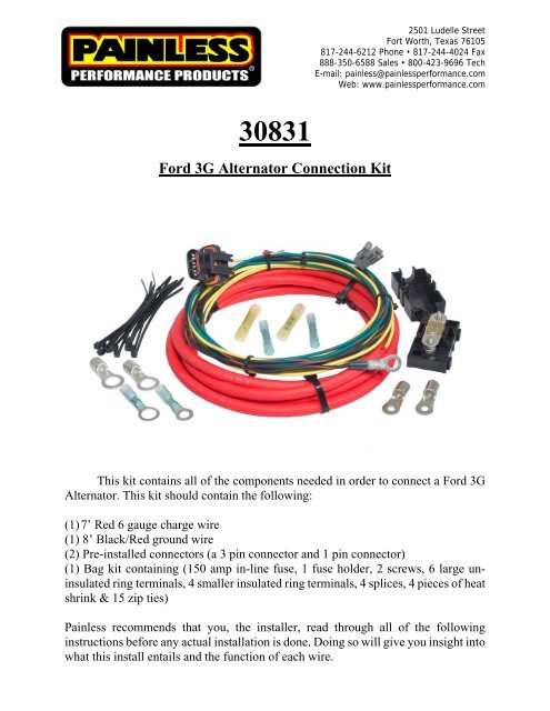
This kit contains all of the components needed in order to connect a <strong>Ford</strong> <strong>3G</strong><br />
<strong>Alternator</strong>. This kit should contain the following:<br />
(1) 7’ Red 6 gauge charge wire<br />
(1) 8’ Black/Red ground wire<br />
(2) Pre-installed connectors (a 3 pin connector and 1 pin connector)<br />
(1) Bag kit containing (150 amp in-line fuse, 1 fuse holder, 2 screws, 6 large uninsulated<br />
ring terminals, 4 smaller insulated ring terminals, 4 splices, 4 pieces of heat<br />
shrink & 15 zip ties)<br />
<strong>Painless</strong> recommends that you, the installer, read through all of the following<br />
instructions before any actual installation is done. Doing so will give you insight into<br />
what this install entails and the function of each wire.
If you are installing a used alternator, <strong>Painless</strong> recommends you have it<br />
tested before installation.<br />
If you are installing this alternator into a vehicle with an Ammeter,<br />
DISCONNECT THE AMMETER. The output of this alternator exceeds the<br />
capabilities of the ammeter and could result in a fire. The wires going to the<br />
ammeter will need to be reconnected together as these wires usually supply<br />
voltage to the fuse block.<br />
Begin the installation by DISCONNECTING THE BATTERY FROM<br />
THE VEHICLE. <strong>Connection</strong>s to the <strong>Alternator</strong> and connections made during<br />
the installation of this kit deal with direct battery power, this step cannot be<br />
skipped.<br />
If the <strong>3G</strong> <strong>Alternator</strong> is already installed on the vehicle, it may need to be removed in<br />
order to make the appropriate connections.<br />
Connect the 3 pin connector and the single pin connector into their proper<br />
locations on back side of the <strong>Alternator</strong>.<br />
Locate the Black/Red wire with the pre-installed ring terminal. This wire will<br />
connect to the “Ground” lug on the <strong>Alternator</strong> ensuring the unit is properly<br />
grounded.<br />
Once connected to the <strong>Alternator</strong>, route the Black/Red wire to a clean chassis<br />
ground source or to the “-” side of the battery. Cut this wire to length and install<br />
an appropriate ring terminal, one of the terminals with the blue heat shrinkable<br />
sheathing, found in the parts kit.<br />
This wire can now be connected to the ground source or to the “-” side of the<br />
battery.<br />
Slide the rubber boot found in the parts kit<br />
over one end of the large red charge wire.<br />
The end of the boot may need to be removed<br />
to fit over the large gauge charge wire.
With the boot installed, crimp a large gauge ring terminal to the charge wire.<br />
Connect this wire to the “B+”, aka Output, stud on the <strong>Alternator</strong>.<br />
Once the nut on this stud has been tightened, the boot can now be slid up the<br />
wire to cover the nut and ring terminal installed on the <strong>Alternator</strong>.<br />
At this point all connections have been made to the <strong>Alternator</strong> itself. If the <strong>Alternator</strong><br />
was removed from the engine brackets to allow access to the connections, it may now<br />
be re-installed on the engine.<br />
Find a suitable location close to the battery to mount the supplied fuse holder<br />
using the 2 screws provided. A drill with a 3/32” or .100” bit will be required<br />
in order to drill holes for the mounting screws<br />
Route the large Red 6 gauge charge wire from the output side of the <strong>Alternator</strong><br />
to one side of the fuse holder. Zip tie the charge wire to mounting points along<br />
its routing path to ensure you have the correct length of wire before any cutting<br />
is done.<br />
Once your length has been established, cut the charge wire to length. The length<br />
of wire cut from the charge wire will be used to connect the supplied fuse to the<br />
“+” side of the vehicle’s battery (<strong>Painless</strong> does not recommended connecting<br />
this charge wire to the Battery side of the starter solenoid).<br />
<strong>Connection</strong> to both sides of the fuse holder will be made using the large ring<br />
terminals with the small #10 hole provided with the kit. These will be the ring<br />
terminals with the small holes. The heat shrink supplied with this kit is intended<br />
to cover the crimped end of each of these two ring terminals as seen below.<br />
Once the ring terminals are installed onto both studs of the fuse holder the fuse<br />
can be installed and everything can be tightened down with the 2 retaining nuts<br />
provided with the fuse holder. Once everything is tightened, the cover can be<br />
reinstalled. Depending on how your crimp flares the ring terminal, the cover<br />
may or may not need slight cutting in order to snap into place.
The Yellow/White wire coming from the 3 pin connector will need to be<br />
connected to a constant power source, as indicated by the print on the wire.<br />
This source will have battery power at all times.<br />
This wire will need to be routed to the constant power source, cut to length, and<br />
connected using a splice found in the parts kit. This splice is heat shrinkable,<br />
meaning after it is crimped, heat can be applied to seal the splice. If your<br />
vehicle originally came with an external voltage regulator, there will be a<br />
suitable constant battery power source at the voltage regulator connector. In<br />
most cases, it will be a Yellow wire.<br />
The Green/Red wire from the 3 pin connector will need to be connected to a<br />
switched power source, as indicated by the print on the wire.. This power<br />
source will only have power when the ignition is in the “run” position.<br />
This wire will need to be routed to the switched power source, cut to length,<br />
and connected using a splice found in the parts kit. This splice is also heat<br />
shrinkable. If your vehicle originally came with an external voltage regulator,<br />
there will be a suitable switched power source at the voltage regulator<br />
connector. In most cases, it will be a Green/Red wire.
At this point all connections have been made, re-connect the vehicle’s battery.<br />
Start the vehicle, and either using the vehicles existing voltage gauge or a hand held<br />
volt meter, ensure the vehicle is charging. You will get a reading of about 14v if<br />
everything is working properly. Any readings of around 12V or below, the vehicle is<br />
not charging, double check all of your connections.<br />
<strong>Painless</strong> Performance Limited Warranty<br />
and Return Policy<br />
Chassis harnesses and fuel injection harnesses are covered under a lifetime warranty.<br />
All other products manufactured and/or sold by <strong>Painless</strong> Performance are warranted to<br />
the original purchaser to be free from defects in material and workmanship under<br />
normal use. <strong>Painless</strong> Performance will repair or replace defective products without<br />
charge during the first 12 months from the purchase date. No products will be<br />
considered for warranty without a copy of the purchase receipt showing the sellers<br />
name, address and date of purchase. You must return the product to the dealer you<br />
purchased it from to initiate warranty procedures.<br />
Copyright 2011 by Perfect Performance Products, LLC


