download pdf - Picto Benelux
download pdf - Picto Benelux
download pdf - Picto Benelux

You also want an ePaper? Increase the reach of your titles
YUMPU automatically turns print PDFs into web optimized ePapers that Google loves.
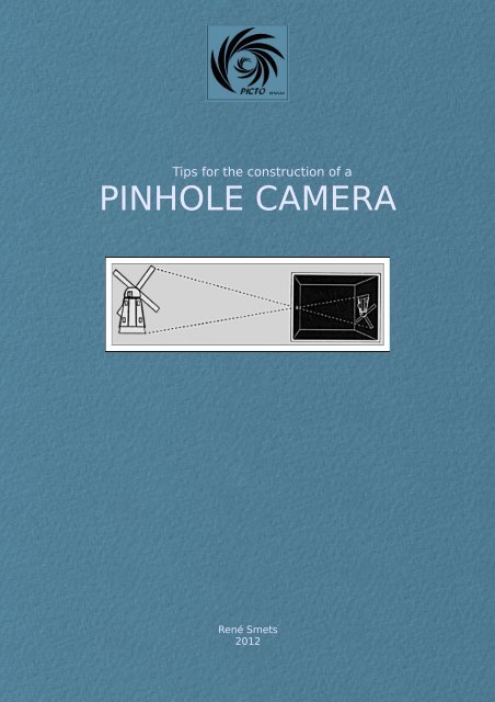
Tips for the construction of a<br />
PINHOLE CAMERA<br />
René Smets<br />
2012
CAMERA OBSCURA.<br />
A couple of centuries before<br />
photography, the principles<br />
related to the pinhole were<br />
already well known, and used<br />
as an assistance in drawing,<br />
under the name of “camera<br />
obscura”.<br />
People noticed indeed that<br />
when light from an external<br />
scene passes through a small<br />
hole and strikes a surface<br />
inside a dark room, it is reproduced upside-down. During the seventeenth century,<br />
painters took advantage of this to produce highly accurate representations of scenes<br />
projected onto paper or canvas on a wall, and traced from there.<br />
The same principles are used in photography to reproduce reality, withg a light<br />
sensitive surface (film or paper) placed in front of the hole. For obvious practical<br />
reasons, the tents used by the early painters have been abandoned since long;<br />
pinhole photography resorts to various light-tight containers, such as metallic cans or<br />
other boxes.<br />
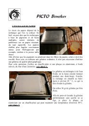
A very simple pinhole camera can be made from a cardboard box: just make a tiny<br />
hole on one side and put a photographic paper inside, on the opposite face. The<br />
proportion between the hole/paper distance and the diameter of the hole is well<br />
known, and the corresponding formulae described everywhere on the web. This<br />
makes it easy to calculate the opening for your specific pinhole camera, and I<br />
therefore will not go deeper into this.<br />
I am building pinhole cameras for several years now, and have to confess that I<br />
wasn't always trying to do it in the simplest way: for my first camera I started from an<br />
old view camera. Since then, I developed a dozen of different models, all of my own<br />
design.<br />
THE HOLE<br />
The main part is the hole, which has to be perfectly<br />
circular, and shouldn't have the shape of a tunnel.<br />
There shouldn't be any trimmings left. The hole<br />
therefore has to be made in a material that is<br />
extremely thin, yet completely opaque. Personnally,<br />
I'm using sheets of brass with a thickness of<br />
0,2mm; you can see them on this picture.
To drill the hole, I am using self-made needles,<br />
the diameters of which do correspond to the<br />
holes I'm needing. I take bicycle spokes for this,<br />
and shape them to model with a very fine<br />
grindstone. I made punches of 0,2-0,3-0,4 and<br />
0,5 mm, corresponding to the diameters needed<br />
for the focal lengths I am mostly using. Putting<br />
heat shrinks on their shaft allows me to show<br />
exactly where the needle has the required<br />
diameter, which is checked with a micrometer<br />
(see picture on the right and sketch #4).<br />
DRILLING THE HOLE<br />
I start drilling the tiniest possible hole in a 2x2cm sheet of<br />
brass, which is about 0,2 mm thick. I do this with an ordinary<br />
needle after putting the sheet on a hard rubber surface (see<br />
sketch 1).<br />
Next, I use a dentist's drill to eliminate the hump on the<br />
backside of the sheet, paying constantly attention to not<br />
enlarge the hole (see sketch 2).<br />
I then smoothen the sheet with a super fine grit sandpaper<br />
(P1200), making sure not to leave any trimming, and checking<br />
this with the hand microscope pictured on the first image<br />
above. I continue flattening out the edges of the hole with a<br />
2mm round-tip needle (see sketch 3).<br />
I continue widening progressively the hole with a needle<br />
having the adequate diameter, and smoothening the edges<br />
after each pass.<br />
CHECKING AND MEASURING<br />
THE HOLE<br />
As said previously, the hole has<br />
to be perfectly round and clean.<br />
To check this, I use an old slide<br />
projector, giving me a crisp image<br />
on a flat surface placed at 1,3 m.<br />
from it. (see picture on the right).
I put a black pvc sheet with a 10mm hole (checked with a micrometer) in a slide mount. This<br />
mount is then put in the projector which is aimed at a sheet of drawing paper fixed on a<br />
vertical support. This allows me to draw the precise diameter of the projected circle, and<br />
finally the circle itself. I part the diameter in 10 divisions, and each of them in 10 subdivisions<br />
(see above).<br />
As a final check, I made a second slide with a 1mm hole that I project on the ink-drawed<br />
circle with its graduated diameter. When measuring a new hole, I make sure first that the<br />
projector is installed in such a way that, when the edge of the drawed circle and the projected<br />
1mm hole coincide, the latter covers exactly 10 subdivisions.<br />
Finally, a put the sheet with the new pinhole in a slide mount and project it on the drawed<br />
circle; in doing so, I can see whether the hole is perfectly round, clean, and what is its<br />
diameter.<br />
For the final touch, I glue the pinhole on a brass sheet with a 5 mm hole and label each<br />
pinhole with its exact size.<br />
René Smets<br />
February 2012<br />
translation: J. Kevers<br />
<strong>Picto</strong> <strong>Benelux</strong><br />
<strong>Picto</strong> is an informal group, open to everybody in the <strong>Benelux</strong> who has an active interest in any<br />
photographic processes developped from the very beginning of Photography. The aim is to revisit<br />
them, while respecting anyone's creative approach.<br />
http://www.picto.info/