HBC DC-DC Series Data Sheet - Power-One
HBC DC-DC Series Data Sheet - Power-One
HBC DC-DC Series Data Sheet - Power-One

You also want an ePaper? Increase the reach of your titles
YUMPU automatically turns print PDFs into web optimized ePapers that Google loves.
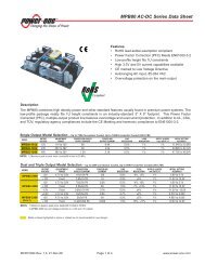
<strong>HBC</strong> <strong>DC</strong>-<strong>DC</strong> <strong>Series</strong> <strong>Data</strong> <strong>Sheet</strong><br />
300-Watt Half-Brick Converters<br />
Applications<br />
Intermediate Bus architectures<br />
Telecommunications equipment<br />
LAN/WAN applications<br />
<strong>Data</strong> processing applications<br />
Features<br />
RoHS lead solder exemption compliant<br />
High efficiency up to 94%<br />
High power density – 110 W/in 3<br />
High current rating - 25 A<br />
Low profile – 12.7mm height<br />
Input/output isolation: 1500 V<strong>DC</strong><br />
Basic insulation<br />
Start-up into high capacitive load<br />
Low conducted and radiated EMI<br />
Output overcurrent protection<br />
Output overvoltage protection<br />
Overtemperature protection<br />
Remote sense<br />
Remote on/off (primary referenced), positive<br />
or negative logic option<br />
Adjustable output voltage from 9.6V to 13.2V<br />
UL 1950 Recognition, CSA 22.2 No. 950-95<br />
certification, TUV IEC950<br />
Description<br />
The <strong>HBC</strong> <strong>Series</strong> of high density bus converters convert a worldwide telecom bus voltage of 36 to 75 V<strong>DC</strong> to a<br />
12 V bus at 25 A. The output is ideal for powering non-isolated, point-of-load converters such as synchronous<br />
buck converters used commonly in intermediate bus architectures.<br />
The unit's open-frame, two-board construction provides ideal thermal transfer for maximum reliability. <strong>Power</strong><br />
devices are mounted on an Insulated Metal Substrate (IMS) base plate with very low thermal impedance. The<br />
control PCB is physically isolated from the hotter IMS board, providing lower overall component temperatures for<br />
high reliability. The standard feature set includes remote on/off, remote output voltage sensing, positive output<br />
trim, input undervoltage lockout, and overtemperature shutdown with hysteresis.<br />
Model Selection<br />
Model<br />
Input<br />
Voltage<br />
V<strong>DC</strong><br />
Input<br />
Current,<br />
Max<br />
A<strong>DC</strong><br />
Output<br />
Voltage<br />
Vout,<br />
V<strong>DC</strong><br />
Output rated<br />
Current<br />
I rated,<br />
A<strong>DC</strong><br />
Output<br />
Ripple/Noise,<br />
mV p-p<br />
Typical<br />
Efficiency @<br />
I rated, %<br />
<strong>HBC</strong>25ZH 36-75 10 12.0 25 150 92<br />
Model numbers highlighted in yellow or shaded are not recommended for new designs.<br />
MCD10036 Rev. 1.0 Page 1 of 7 www.power-one.com
<strong>HBC</strong> <strong>DC</strong>-<strong>DC</strong> <strong>Series</strong> <strong>Data</strong> <strong>Sheet</strong><br />
300-Watt Half-Brick Converters<br />
Absolute Maximum Ratings<br />
Stresses in excess of the absolute maximum ratings may cause performance degradation, adversely effect<br />
long-term reliability, and cause permanent damage to the converter.<br />
Parameter Conditions/Description Min Max Units<br />
Input voltage<br />
Continuous<br />
Transient, 100ms<br />
75<br />
100<br />
V<strong>DC</strong><br />
V<strong>DC</strong><br />
Operating Temperature Base Plate Temperature -40 110 C<br />
Storage Temperature -55 125 C<br />
ON/OFF Control Voltage Referenced to -Vin 7 V<strong>DC</strong><br />
Environmental and Mechanical Specifications<br />
All specifications apply over specified input voltage, output load, and temperature range, unless otherwise noted.<br />
Parameter Conditions/Description Min Nom Max Units<br />
Shock Halfsine wave, 3 axes 50 g<br />
Sinusoidal Vibration GR-63-CORE, Section 5.4.2 1 g<br />
Weight 2.6/73 oz/gm<br />
Water Washing Standard process Yes<br />
MTBF Per Bellcore TR-NWT-000332 1,100 kHrs<br />
Isolation Specifications<br />
All specifications apply over specified input voltage, output load and temperature range, unless otherwise noted.<br />
Parameter Conditions/Description Min Nom Max Units<br />
Insulation Safety Rating<br />
Basic<br />
Isolation Voltage Input to output, output to base plate 1500 V<strong>DC</strong><br />
Isolation Voltage Input to base plate 1500 V<strong>DC</strong><br />
Isolation Resistance 10 MOhm<br />
Isolation Capacitance 1000 pF<br />
Input Specifications<br />
All specifications apply over specified input voltage, output load and temperature range, unless otherwise noted.<br />
Parameter Conditions/Description Min Nom Max Units<br />
Input Voltage Continuous 36 48 75 V<strong>DC</strong><br />
Turn-On Input Voltage Ramping Up 33 36 V<strong>DC</strong><br />
Turn-Off Input Voltage Ramping Down 31 33 V<strong>DC</strong><br />
Turn-On Time for turn-on via Time from Vin=UVLO to regulation<br />
60 85 ms<br />
application of input voltage<br />
band<br />
Turn-On Time for turn-on via<br />
Time from ON/OFF signal to<br />
10 25 ms<br />
ON/OFF signal<br />
regulation band<br />
Input Reflected Ripple Current Full Load, 12H source inductance 200 mA p-p<br />
Inrush Transient Vin=Vin.max 0.25 A 2 s<br />
MCD10036 Rev. 1.0 Page 2 of 7 www.power-one.com
<strong>HBC</strong> <strong>DC</strong>-<strong>DC</strong> <strong>Series</strong> <strong>Data</strong> <strong>Sheet</strong><br />
300-Watt Half-Brick Converters<br />
Output Specifications<br />
All specifications apply over specified input voltage, output load, and temperature range, unless otherwise noted.<br />
Parameter Conditions/Description Min Nom Max Units<br />
Output Voltage Setpoint Accuracy Vin=Vin.nom, Full Load -2 2 %Vout<br />
Output Current* See selection chart for I rated 0 25 A<br />
Line Regulation Vin.min to Vin.max, I rated 0.5 %Vout<br />
Load Regulation Vin=Vin.nom, 10% to 100%I rated 1.0 %Vout<br />
Total output voltage regulation Over all input voltage, load, and -4 4 %Vout<br />
temperature conditions<br />
Remote Sense Headroom 5% %Vout<br />
Dynamic Regulation<br />
Peak Deviation<br />
Settling Time<br />
75-100% load step change<br />
to 1% error band<br />
600<br />
600 1,000<br />
Admissible Load Capacitance I rated , Nom Vin 15,000 F<br />
Output Current Limit Threshold** Vout0.97Vout.nom 110 150 %I rated<br />
Switching Frequency 400 kHz<br />
Overvoltage Protection,<br />
Latching<br />
Over all input voltage and load<br />
conditions<br />
mV<br />
s<br />
115 125 %Vout<br />
Trim Range I rated , Vin=Vnom 80 110 %Vout<br />
** Overcurrent protection is non-latching with auto recovery.<br />
Feature Specifications<br />
All specifications apply over specified input voltage, output load, and temperature range, unless otherwise noted.<br />
Parameter Conditions/Description Min Nom Max Units<br />
Shutdown (ON/OFF)<br />
Negative Logic<br />
Converter ON<br />
Source Current<br />
Converter OFF<br />
Open Circuit Voltage<br />
Positive Logic<br />
Converter ON<br />
Open Circuit Voltage<br />
Converter OFF<br />
Source Current<br />
On/Off signal is low – converter is ON<br />
ON/OFF pin is connected to -Vin<br />
ON/OFF pin is floating<br />
On/Off signal is low–converter is OFF<br />
-0.5<br />
2.5<br />
0.8<br />
0.5<br />
7<br />
5<br />
V<strong>DC</strong><br />
MA<strong>DC</strong><br />
V<strong>DC</strong><br />
V<strong>DC</strong><br />
2.5<br />
7 V<strong>DC</strong><br />
ON/OFF pin is floating<br />
5 V<strong>DC</strong><br />
-0.5<br />
0.8 V<strong>DC</strong><br />
ON/OFF pin is connected to -Vin<br />
0.5 mA<strong>DC</strong><br />
Overtemperature Protection Base Plate Temperature 120 130 C<br />
MCD10036 Rev. 1.0 Page 3 of 7 www.power-one.com
<strong>HBC</strong> <strong>DC</strong>-<strong>DC</strong> <strong>Series</strong> <strong>Data</strong> <strong>Sheet</strong><br />
300-Watt Half-Brick Converters<br />
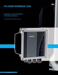
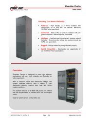
Efficiency Curves<br />
EFFICIENCY %<br />
95<br />
90<br />
85<br />
80<br />
75<br />
36V<br />
48V<br />
75V<br />
0 20 40 60 80 100<br />
LOAD %<br />
Figure 1. <strong>HBC</strong>25ZH Efficiency vs. Output Load<br />
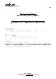
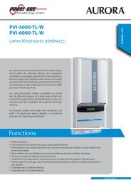
Typical Application<br />
Figure 2 shows the recommended connections for the<br />
<strong>HBC</strong> <strong>Series</strong> converter.<br />
Fuse<br />
+Vi<br />
<strong>HBC</strong>25ZH<br />
+Vo<br />
+Sense<br />
C1 C2 C3<br />
On/Off<br />
Trim<br />
-Sense<br />
(AVX TPSC106M025R0500 is used in our test<br />
setup) and a 1 F ceramic capacitor. Note, that<br />
the capacitors do not substitute the filtering<br />
required by the load.<br />
Shutdown Feature Description<br />
The ON/OFF pin in the <strong>HBC</strong> <strong>Series</strong> converters<br />
functions as a normal soft shutdown. It is<br />
referenced to the –Vin pin (see Figure 2). With<br />
the positive logic, when the ON/OFF pin is pulled<br />
low, the output is turned off and the unit goes into<br />
a very low input power mode.<br />
With negative logic, when the ON/OFF pin is<br />
pulled low, the unit is turned on.<br />
An open collector switch is recommended to<br />
control the voltage between the ON/OFF pin and<br />
the -Vin pin of the converter. The ON/OFF pin is<br />
pulled up internally, so no external voltage source<br />
is required. The user should avoid connecting a<br />
resistor between the ON/OFF pin and the +Vin<br />
pin.<br />
When the ON/OFF pin is used to achieve remote<br />
control, the user must take care to ensure that the<br />
pin reference for the control is really the -Vin pin.<br />
The control signal must not be referenced ahead<br />
of EMI filtering, or remotely from the unit.<br />
Optically coupling the information and locating the<br />
optical coupler directly at the module will solve<br />
any of these problems.<br />
Note:<br />
If the ON/OFF pin is not used, it can be left floating (positive<br />
logic), or connected to the -Vin pin (negative logic).<br />
-Vi<br />
-Vo<br />
OUTPUT VOLTAGE TRIM<br />
Figure 2. Typical Application of <strong>HBC</strong> <strong>Series</strong><br />
The <strong>HBC</strong> <strong>Series</strong> converters do not require any external<br />
components for proper operation. However, if the<br />
distribution of the input voltage to the converter contains<br />
significant inductance, the capacitor C1 may be<br />
required to enhance performance of the converter. A<br />
minimum of a 68 F electrolytic capacitor with the<br />
ESR
<strong>HBC</strong> <strong>DC</strong>-<strong>DC</strong> <strong>Series</strong> <strong>Data</strong> <strong>Sheet</strong><br />
300-Watt Half-Brick Converters<br />
to receive safety agency approval, certain rules<br />
must be followed in the design of the system. In<br />
particular, all of the creepage and clearance<br />
requirements of the end-use safety requirements<br />
must be observed. These documents include<br />
UL60950 - CSA60950-00 and EN60950, although<br />
other or additional requirements may be needed<br />
for specific applications.<br />
Figure 3. <strong>HBC</strong> <strong>Series</strong> Positive Trim Schematic<br />
The equations below determine the trim resistor value<br />
required to achieve a V change in the output voltage.<br />
Vo(100<br />
%)<br />
(100 2%)<br />
<br />
Rup <br />
<br />
k<br />
1.225%<br />
%<br />
<br />
100 <br />
Rdown 2)<br />
k<br />
%<br />
<br />
where V% is the output voltage change expressed in<br />
percents of the nominal output voltage, Vo.<br />
Notes:<br />
1. When the output voltage is trimmed up, the output power from<br />
the converter must not exceed its maximum rating. The power is<br />
determined by measuring the output voltage on the output pins,<br />
and multiplying it by the output current.<br />
2. In order to avoid creating apparent load regulation degradation, it<br />
is important that the trim resistors are connected directly to the<br />
remote sense pins, and not to the load or to traces going to the<br />
load.<br />
3. The output voltage increase can be accomplished by either the<br />
trim or by the remote sense or by the combination of both. In<br />
any case the absolute maximum output voltage increase shall<br />
not exceed 10% of the nominal output voltage<br />
Safety Considerations<br />
The <strong>HBC</strong> <strong>Series</strong> converters feature 1500 Volt <strong>DC</strong><br />
isolation from input to output. The input to output<br />
resistance is greater than 10 M. These converters are<br />
provided with basic insulation between input and output<br />
circuits according to all IEC60950 based standards.<br />
Nevertheless, if the system using the converter needs<br />
The <strong>HBC</strong> <strong>Series</strong> converters have no internal fuse.<br />
The external fuse must be provided to protect the<br />
system from catastrophic. The user can select a<br />
fuse based upon the highest inrush transient at<br />
the maximum input voltage and the maximum<br />
input current of the converter, which occurs at the<br />
minimum input voltage. Both input traces and the<br />
chassis ground trace (if applicable) must be<br />
capable of conducting a current of 1.5 times the<br />
value of the fuse without opening. The fuse must<br />
not be placed in the grounded input line, if any.<br />
In order for the output of the <strong>HBC</strong> <strong>Series</strong><br />
converter to be considered as SELV (Safety Extra<br />
Low Voltage) or TNV-1, according to all IEC60950<br />
based standards, one of the following<br />
requirements must be met in the system design:<br />
<br />
<br />
<br />
If the voltage source feeding the module is<br />
SELV or TNV-2, the output of the converter<br />
may be grounded or ungrounded.<br />
If the voltage source feeding the module is<br />
ELV, the output of the converter may be<br />
considered SELV only if the output is<br />
grounded per the requirements of the<br />
standard.<br />
If the voltage source feeding the module is a<br />
Hazardous Voltage Secondary Circuit, the<br />
voltage source feeding the module must be<br />
provided with at least basic insulation<br />
between the source to the converter and any<br />
hazardous voltages. The entire system,<br />
including the <strong>HBC</strong> converter, must pass a<br />
dielectric withstand test for reinforced<br />
insulation. Design of this type of systems<br />
requires expert engineering and understanding<br />
of the overall safety requirements<br />
and should be performed by qualified<br />
personnel.<br />
Thermal Considerations<br />
The <strong>HBC</strong> <strong>Series</strong> converters are designed for<br />
natural or forced convection cooling. The<br />
maximum allowable output current of the<br />
MCD10036 Rev. 1.0 Page 5 of 7 www.power-one.com
<strong>HBC</strong> <strong>DC</strong>-<strong>DC</strong> <strong>Series</strong> <strong>Data</strong> <strong>Sheet</strong><br />
300-Watt Half-Brick Converters<br />
converters is determined by meeting the derating<br />
criteria for all components used in the converters. For<br />
example, the maximum semiconductor junction<br />
temperature is not allowed to exceed 125 °C to ensure<br />
reliable long-term operation of the converters. Contact<br />
<strong>Power</strong>-<strong>One</strong> for the complete list of the derating criteria.<br />
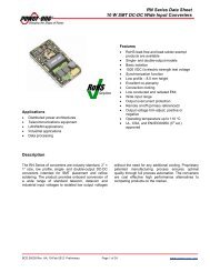
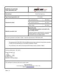
30<br />
25<br />
20<br />
THERMAL DERATING CURVE<br />
<strong>HBC</strong>25ZH-T, -NT<br />
Vin = 54V, Orientation : Vin- to Vin +<br />
<strong>Data</strong> Rev: 01<br />
The graph in Figure 4 shows the maximum output<br />
current of the <strong>HBC</strong> <strong>Series</strong> converter at different ambient<br />
temperatures under both natural and forced<br />
(longitudinal airflow direction, from pin 1 to pin 4)<br />
convection.<br />
Load Current (A)<br />
15<br />
10<br />
5<br />
NC (25 - 35 LFM) 100 LFM 200 LFM 300 LFM 400 LFM<br />
0<br />
25 40 55 70 85<br />
Ambient Temperature (Deg C)<br />
Figure 4. <strong>HBC</strong>25ZH-T, NT Derating Curves<br />
For example, from Figure 4, the <strong>HBC</strong>25ZH<br />
operating at 45 ºC can deliver up to 19 A reliably<br />
with 200 LFM forced air, while up to 23 A reliably<br />
with 400 LFM forced air.<br />
MCD10036 Rev. 1.0 Page 6 of 7 www.power-one.com
<strong>HBC</strong> <strong>DC</strong>-<strong>DC</strong> <strong>Series</strong> <strong>Data</strong> <strong>Sheet</strong><br />
300-Watt Half-Brick Converters<br />
Mechanical Drawing<br />
Pin Function<br />
1 -Vin<br />
2 Case<br />
3 On/off<br />
4 +Vin<br />
5 -Vout<br />
6 -Sense<br />
7 Trim<br />
8 +Sense<br />
9 +Vout<br />
Mechanical Tolerances<br />
Inches<br />
Millimeters<br />
X.XX ±0.020 X.X ±0.5<br />
X.XXX ±0.010 X.XX ±0.25<br />
Ordering Information<br />
Options<br />
Remote ON/OFF<br />
Trim<br />
Pin Length<br />
Pin<br />
±0.002 ±0.05<br />
Suffixes to add to part number<br />
Positive- Standard, no suffix required<br />
Negative- Add “N” suffix<br />
Positive - “T” suffix (required - all models)<br />
0.18”- Standard, no suffix required<br />
0.145”- Add “7” suffix<br />
0.110”- Add “8” suffix<br />
Example: <strong>HBC</strong>25ZH-T8 is a positive on/off logic, industry standard Trim, 12 V output converter with 0.110” pin<br />
length<br />
Notes<br />
1. Consult factory for the complete list of available options.<br />
NUCLEAR AND MEDICAL APPLICATIONS - <strong>Power</strong>-<strong>One</strong> products are not designed, intended for use in, or authorized for use as critical<br />
components in life support systems, equipment used in hazardous environments, or nuclear control systems without the express written<br />
consent of the respective divisional president of <strong>Power</strong>-<strong>One</strong>, Inc.<br />
TECHNICAL REVISIONS - The appearance of products, including safety agency certifications pictured on labels, may change depending on<br />
the date manufactured. Specifications are subject to change without notice.<br />
MCD10036 Rev. 1.0 Page 7 of 7 www.power-one.com