BALL LOCK ® MOUNTING SYSTEM QUICK CHANGE ... - Jergens Inc.
BALL LOCK ® MOUNTING SYSTEM QUICK CHANGE ... - Jergens Inc.
BALL LOCK ® MOUNTING SYSTEM QUICK CHANGE ... - Jergens Inc.

You also want an ePaper? Increase the reach of your titles
YUMPU automatically turns print PDFs into web optimized ePapers that Google loves.
www.jergensinc.com<br />
<strong>BALL</strong> <strong>QUICK</strong> <strong>LOCK</strong> ®<br />
<strong>CHANGE</strong> <strong>MOUNTING</strong> FIXTURING <strong>SYSTEM</strong><br />
1<br />
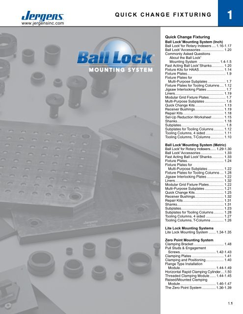
Quick Change Fixturing<br />
Ball Lock ® Mounting System (<strong>Inc</strong>h)<br />
Ball Lock ® for Rotary Indexers..... 1.16-1.17<br />
Ball Lock ® Accessories........................ 1.20<br />
Commonly Asked Questions<br />
About the Ball Lock ®<br />
Mounting System ...................... 1.4-1.5<br />
Fast Acting Ball Lock ® Shanks............. 1.20<br />
Fixture Kits for HAAS.......................... 1.14<br />
Fixture Plates........................................ 1.9<br />
Fixture Plates for<br />
Multi-Purpose Subplates................... 1.7<br />
Fixture Plates for Tooling Columns..... 1.12<br />
Jigsaw Interlocking Plates.................... 1.7<br />
Liners.................................................. 1.19<br />
Modular Grid Fixture Plates.................. 1.7<br />
Multi-Purpose Subplates...................... 1.6<br />
Quick Change Kits.............................. 1.13<br />
Receiver Bushings.............................. 1.19<br />
Repair Kits.......................................... 1.18<br />
Set-Up Reduction Worksheet............. 1.15<br />
Shanks................................................ 1.18<br />
Subplates.............................................. 1.8<br />
Subplates for Tooling Columns........... 1.12<br />
Tooling Columns, 4 sided................... 1.11<br />
Tooling Columns, T-Columns.............. 1.10<br />
Ball Lock ® Mounting System (Metric)<br />
Ball Lock ® for Rotary Indexers...... 1.29-1.30<br />
Ball Lock ® Accessories........................ 1.33<br />
Fast Acting Ball Lock ® Shanks............. 1.33<br />
Fixture Plates...................................... 1.24<br />
Fixture Plates for<br />
Multi-Purpose Subplates................. 1.22<br />
Fixture Plates for Tooling Columns..... 1.28<br />
Jigsaw Interlocking Plates.................. 1.22<br />
Liners.................................................. 1.32<br />
Modular Grid Fixture Plates................ 1.22<br />
Multi-Purpose Subplates.................... 1.21<br />
Quick Change Kits.............................. 1.25<br />
Receiver Bushings.............................. 1.32<br />
Repair Kits.......................................... 1.31<br />
Shanks................................................ 1.31<br />
Subplates............................................ 1.23<br />
Subplates for Tooling Columns........... 1.28<br />
Tooling Columns, 4 sided................... 1.27<br />
Tooling Columns, T-Columns.............. 1.26<br />
Lite Lock Mounting Systems<br />
Lite Lock Mounting System........ 1.34-1.35<br />
Zero Point Mounting System<br />
Clamping Bracket............................... 1.48<br />
Pull Studs & Engagement<br />
Screws..................................... 1.42-1.43<br />
Clamping Plates................................. 1.41<br />
Clamping and Positioning................... 1.40<br />
Flange Type Installation<br />
Module..................................... 1.44-1.49<br />
Horizontal Rapid Clamping Cylinder.....1.50<br />
Threaded Clamping Module....... 1.44-1.45<br />
Raised/Mounted Clamping<br />
Module..................................... 1.46-1.47<br />
The Zero Point System............... 1.36-1.39<br />
Phone 800-537-4367 or +1 216-486-5540 • Fax: +1 216-481-6193 • E-mail: info@jergensinc.com • www.jergensinc.com 1.1
1 <strong>BALL</strong> <strong>LOCK</strong> ® <strong>MOUNTING</strong> <strong>SYSTEM</strong><br />
www.jergensinc.com<br />
We Put It All Together… In Seconds.<br />
Maximize productivity levels and<br />
dramatically increase throughput with<br />
Ball Lock ® .<br />
Looking to realize the full benefits of lean manufacturing? Then<br />
you need the one system that puts it all together, so you can put<br />
it all together…and that’s Ball Lock ® .<br />
Ball Lock ® is the industry’s most popular quick-change, fixturingflexible<br />
mounting system that can be configured to create leanoptimized<br />
solutions for your most demanding needs.<br />
The Ball Lock ® Mounting System is used as a<br />
Quick Change Solution on the following:<br />
• CNC Machines<br />
• Palletized Fixtures<br />
• Stamping<br />
• Fabricating<br />
• Injection Molding<br />
• Packaging Machines<br />
• Assembly Machines<br />
• EDM<br />
• Robotics<br />
• Welding Fixtures<br />
1.2<br />
<strong>Jergens</strong>, <strong>Inc</strong>. • <strong>Jergens</strong> Way • 15700 S. Waterloo Road • Cleveland, Ohio 44110-3898 USA
www.jergensinc.com<br />
<strong>BALL</strong> <strong>LOCK</strong> ®<br />
<strong>MOUNTING</strong> <strong>SYSTEM</strong><br />
1<br />
Lean Manufacturing and Set Up Reduction Applications<br />
Accurately Locate and Lock Fixture Plates to Subplates in Seconds…<br />
With No Indicating Required.<br />
Machining Cast Part<br />
Previous Set Up Method:<br />
Located part with dowel pins, bolted part to tombstone<br />
fixture. Indicated part to zero datum point.<br />
Set Up Using Ball Lock ® System:<br />
Mount parts to fixture plate while machining other<br />
parts. Mount fixture plate to tombstone using Ball<br />
Lock ® shanks. No indicating required because<br />
system provides + 0.0005 (±0.013mm)repeatability.<br />
Previous Set-Up Time:<br />
15 minutes<br />
Set Up Time With Ball Lock ® System:<br />
60 seconds<br />
CNC Machine Base:<br />
Drilling and reaming forged part.<br />
Previous Set Up Method:<br />
Fixture plate located with dowel pins bolted to<br />
machine base. Fixture plate and parts indicated.<br />
Set Up Using Ball Lock ® System:<br />
Parts are pre-mounted on fixture plate, which is<br />
then mounted to machine base using Ball Lock ®<br />
shanks. No need to indicate.<br />
Previous Set Up Time:<br />
7 minutes<br />
Set Up Time with Ball Lock ® System:<br />
60 seconds<br />
CNC Vertical Machining Center<br />
Machining aircraft valve parts<br />
Previous Set Up Method:New Project. New<br />
Machine.No Prior History.<br />
Set Up Using Ball Lock ® System:Using Ball<br />
Lock ® Jig Saw Plate on Multi-Purpose Subplate<br />
enables operator to mount two more vises on<br />
the fixture. No indicating needed.<br />
Previous Set Up Time:<br />
New Set Up.<br />
Set Up Time With Ball Lock ® System:<br />
80 seconds setting up six vises.<br />
Two-Sided Tombstone<br />
Drilling and tapping cylindrical bodies.<br />
Previous Set Up Method:<br />
Fixture located and bolted to tombstone. Had to<br />
be indicated.<br />
Set Up Using Ball Lock ® System:<br />
Fixture plate mounted and located with Ball Lock ®<br />
shanks. No need to indicate.<br />
Previous Set Up Time:<br />
12 minutes<br />
Set Up Time with Ball Lock ® System:<br />
45 seconds<br />
Phone 800-537-4367 or +1 216-486-5540 • Fax: +1 216-481-6193 • E-mail: info@jergensinc.com • www.jergensinc.com 1.3
1 <strong>BALL</strong> <strong>LOCK</strong> ® <strong>MOUNTING</strong> <strong>SYSTEM</strong><br />
www.jergensinc.com<br />
Locates<br />
The Ball Lock ® System accurately positions<br />
your fixtureplate with a repeatability of<br />
±0.0005" (±0.013mm) or better, minimizing<br />
the need to indicate your fixture.<br />
Locks<br />
The Ball Lock ® System securely holds fixture<br />
plates to subplates with up to 20,000 lbs.<br />
(9000 kg) of hold-down force per shank.<br />
The Ball Lock ® Mounting System is designed<br />
to speed the accurate locating and locking<br />
of fixture plates to subplates. The system<br />
consists of three parts: a Locating Shank,<br />
a Liner Bushing, and a Receiver Bushing.<br />
Using the Ball Lock ® Mounting System is<br />
a simple process: Install a subplate with<br />
receiver bushings on your machine table;<br />
add your fixture plate with two locating liner<br />
bushings; then insert two locating shanks<br />
through the liners and into the receiver<br />
bushings to provide accurate location.<br />
2 1 / 2 turns of the set screw in each of the<br />
locating shanks provides positive holding<br />
force. Additional Ball Lock ® Shanks are<br />
inserted through clearance holes in the<br />
fixture plate and set screws tightened for<br />
additional holding force distributed across<br />
the fixture plate.<br />
It is recommended that the use of<br />
the Ball Lock ® Mounting System for<br />
locating and clamping of fixture plates<br />
be incorporated in a systematic<br />
process. All fixture plates should<br />
have two locating points positioned<br />
as far apart as possible. There is no<br />
advantage to having more than two<br />
The Ball Lock ® Mounting System<br />
provides a method of quickly and<br />
accurately locating fixtures onto<br />
machine tables. The Ball Lock ®<br />
Mounting System has done for<br />
machining centers what the Japanese<br />
SMED concept did for presses.<br />
Instead of single minute exchange of<br />
dies, Ball Lock ® provides single minute<br />
exchange of fixtures. Fixtures can<br />
often be exchanged in less than a<br />
minute and with position repeatability<br />
of ±0.0005” (±0.013mm). Fixtures<br />
can be exchanged between different<br />
machines when both are using the<br />
<strong>Jergens</strong> Ball Lock ® Mounting System.<br />
Commonly Asked Questions<br />
Q. What is the Ball Lock ®<br />
Mounting System?<br />
A. It is a means of locating and locking<br />
two flat surfaces together, normally a<br />
fixture plate and a sub-plate.<br />
Q. How does it locate?<br />
A. Similar to locating pins, two Ball<br />
Lock ® shanks (pins) pass through two<br />
precision liner bushings on the fixture<br />
plate and into two precision receiver<br />
bushings on the subplate.<br />
Q. How does it lock?<br />
A. Inside the shank are three balls that<br />
expand into a tapered groove in the<br />
receiver bushing. This action draws<br />
the plates together. The locking balls<br />
are activated by turning a setscrew in<br />
the head of the shank, which pushes<br />
a 4th ball to distribute the clamping<br />
forces between the 3 locking balls.<br />
Q. How many shanks are required<br />
to locate and lock each fixture?<br />
A. Only two shanks, passing through<br />
bushings in the fixture plates, are<br />
required for location. However,<br />
additional shanks passing through<br />
clearance holes in the fixture plate<br />
will provide additional holding force<br />
distributed across the plate.<br />
1.4<br />
<strong>Jergens</strong>, <strong>Inc</strong>. • <strong>Jergens</strong> Way • 15700 S. Waterloo Road • Cleveland, Ohio 44110-3898 USA
www.jergensinc.com<br />
<strong>BALL</strong> <strong>LOCK</strong> ®<br />
<strong>MOUNTING</strong> <strong>SYSTEM</strong><br />
1<br />
Ball Lock ®<br />
Shank<br />
Liner Bushing<br />
Ball Lock ®<br />
Shank<br />
Liner Bushing<br />
Fixture Plate<br />
Fixture Plate<br />
Slip Fit Hole<br />
Socket Head Cap<br />
Screws (3)<br />
Press Fit Hole<br />
Machine<br />
Table or<br />
Subplate<br />
Face Mount<br />
Bushing<br />
Drilled Hole<br />
Subplate<br />
Counter-Bored<br />
Hole<br />
Back Mount Bushing<br />
Mounting Method With<br />
Face Mount Bushing<br />
Mounting Method With<br />
Back Mount Bushing<br />
locating points. If more than two flanged<br />
shanks are required to provide additional<br />
hold- down force, omit liner bushings in<br />
the additional holes in the fixture plate and<br />
allow 0.030" (0.76mm) over the nominal<br />
size. The additional clearance will insure<br />
that these holes have no influence on the<br />
locating holes.<br />
How accurate should positioning be?<br />
The center distance of the receiver bushings<br />
in the machine table, tombstone, or subplate<br />
should be as accurate as possible ±0.0002"<br />
(±0.005mm) recommended. Accurate<br />
location will assure interchangeability of<br />
numerous fixture plates. For accurate<br />
repeatability within ±0.0005" (±0.013mm)<br />
of true position, both liner bushings in the<br />
fixture plate should be primary liners and<br />
the center distance tolerance should be<br />
±0.0002" (±0.005mm). For a slightly looser<br />
fit, repeatability within 0.0015" (0.04mm)<br />
of true position, use one primary and one<br />
secondary liner with a center distance<br />
tolerance of ±0.001" (±0.003mm).<br />
Q. Is there a preferable location for<br />
the liner bushing?<br />
A. System repeatability is improved<br />
if the liners are located at opposite<br />
corners of a rectangular fixture plate.<br />
For consistency, we recommend<br />
locating the liner bushings at top left<br />
and bottom right.<br />
Q. What are the advantages of using<br />
the Ball Lock ® System over the<br />
conventional method of dowel<br />
pins and cap screws?<br />
A. Both locating and locking are<br />
accomplished in the same motion. Ball<br />
Lock ® shanks require only 2.5 turns<br />
to lock a 1/2–13 (M12) screw with ¾"<br />
(18mm) of thread engagement require<br />
10 turns to lock. On CNC machines,<br />
the repeatability of fixture locations<br />
makes indicating of the fixture<br />
unnecessary.<br />
Q. How do I recess the fixtureplate<br />
for a clear surface ?<br />
A. Counterbore the fixture plate to a<br />
diameter large enough to allow easy<br />
removal of the shank.<br />
Note: The thickness of the plate section<br />
under the head of the shank is critical and<br />
must conform to mounting instructions .<br />
Q. What if my plate is thinner than<br />
the recommended thickness?<br />
A. By adjusting the depth of the<br />
counterbore for the receiver bushing<br />
in the subplate, you can still use the<br />
Ball Lock ® System. If there are any<br />
questions on this type of application,<br />
please call 1-800-JERGENS.<br />
Q. Can I use the shanks in a heated<br />
environment?<br />
A. The shank is made of alloy steel,<br />
heat treated to 40-45Rc and should<br />
with stand temperatures up to 400°F.<br />
(200°C).<br />
Note: Thermal expansion of fixture plates<br />
may affect the center distance tolerance<br />
and repeatability.<br />
Phone 800-537-4367 or +1 216-486-5540 • Fax: +1 216-481-6193 • E-mail: info@jergensinc.com • www.jergensinc.com 1.5
1 <strong>BALL</strong> <strong>LOCK</strong> ® <strong>MOUNTING</strong> <strong>SYSTEM</strong><br />
INCH DIMENSIONS<br />
www.jergensinc.com<br />
INCH PRE-MACHINED FIXTURE/SUBPLATES<br />
Multi-Purpose Subplates<br />
40x20 Multi-Purpose Subplate<br />
Part Number Wt. (lbs)<br />
49112 285<br />
The <strong>Jergens</strong> Multi-Purpose Subplate accommodates<br />
a wide variety of fixture plates and vises. This<br />
versatility facilitates using the same VMC for<br />
diverse products in repetitive runs, long and short<br />
batch sizes.<br />
• FreMax 15 Steel or Equivalent<br />
• Thickness: 1 1/4” ±0.005"<br />
• Parallel within 0.001"<br />
28706<br />
28801<br />
49406<br />
28719<br />
28713 or 28715<br />
28727<br />
49112<br />
17.0000<br />
12.0000<br />
17.0000<br />
12.0000<br />
(18) 20MM FACE MOUNT<br />
BUSHINGS<br />
INSTALLED<br />
5/8" BORED HOLE<br />
FOR SINE<br />
FIXTURE KEYS<br />
(2) PLACES<br />
6.0000<br />
12.0000<br />
20<br />
17.0000<br />
(8) 25MM FACE MOUNT<br />
BUSHINGS<br />
INSTALLED<br />
8.0000<br />
8.0000<br />
8.0000<br />
8.0000<br />
40<br />
Fixture Plate Options for Multi-Purpose Subplates – Aluminum or Steel<br />
Number of Fixture Receiver Required Number<br />
Plates/Vises That Mount Bushing Receiver Ball Lock ® of Shanks<br />
Fixture Plate*/Vise Thickness of on Multi-Purpose Center Bushing Shank Required Per<br />
Part Number Fixture Plate Subplate Distance Size Part Number Fixture Plate/Vise<br />
28713 (14 x 14)<br />
Fixture Plate<br />
28715 (16 x 16)<br />
Fixture Plate<br />
28801 (16 x 16)<br />
Modular Grid Plate<br />
28706 Jigsaw<br />
Interlocking Plate<br />
28727 (20 x 20)<br />
Fixture Plate<br />
28719 (20 x 16)<br />
Fixture Plate<br />
49406<br />
6" Jigsaw Base Vise<br />
3/4” 2 12 x 12 20 mm 49601 4<br />
3/4” 2 12 x 12 20 mm 49601 4<br />
1 1/8”** 2 12 x 12 20 mm 49602 4<br />
3/4” 4 8 x 12 20 mm 49601 3<br />
1” 2 17 x 17 25 mm 49612 4<br />
3/4" 1 16 x 12 20 mm 49601 4<br />
3/4" 4 8 x 12 20 mm 49601 3<br />
* See next page for dimensional data on fixture plates. Part numbers shown for aluminum plates, also available in steel.<br />
** Counterbored to 1" at mounting holes.<br />
1.6<br />
<strong>Jergens</strong>, <strong>Inc</strong>. • <strong>Jergens</strong> Way • 15700 S. Waterloo Road • Cleveland, Ohio 44110-3898 USA
www.jergensinc.com<br />
<strong>BALL</strong> <strong>LOCK</strong> ®<br />
<strong>MOUNTING</strong> <strong>SYSTEM</strong><br />
INCH DIMENSIONS<br />
1<br />
Fixture Plates for Multi-Purpose Subplate<br />
14x14x3/4" Fixture Plate<br />
Aluminum Plate<br />
Part Number Wt. (lbs)<br />
28713 14<br />
16x16x3/4" Fixture Plate<br />
Aluminum Plate<br />
Part Number Wt. (lbs)<br />
28715 18<br />
Steel Plate<br />
Part Number Wt. (lbs)<br />
28813 42<br />
Steel Plate<br />
Part Number Wt. (lbs)<br />
28815 55<br />
• Cast Aluminum or FreMax 15 Steel or equivalent<br />
• Thickness: 3/4" ±0.005"<br />
• Parallel within 0.001" Steel<br />
• Mounts to subplates with Ball Lock ® Shank 49601 (20 X 3/4")<br />
16x16 Modular Grid Fixture Plate<br />
Steel Plate<br />
Part Number Wt. (lbs)<br />
28801 80<br />
(2) 20MM<br />
PRIMARY LINERS<br />
• FreMaxINSTALLED<br />
(2) PLACES<br />
15 Steel or equivalent<br />
• Thickness: 1 1/8” ±0.005"<br />
• Parallel within 0.001"<br />
• Mounts to subplates with Ball Lock ®<br />
Shank 49602 (20 x 1")<br />
(2) 20MM<br />
PRIMARY LINERS<br />
INSTALLED<br />
CLEARANCE HOLES<br />
FOR HOLDDOWN<br />
CLEARANCE<br />
12.0000<br />
HOLES<br />
FOR HOLDDOWN<br />
(2) PLACES 16.0000<br />
-0.000<br />
.625 +0.0005 x .25 Deep<br />
COUNTERBORE<br />
1/2-13<br />
TAPPED HOLE<br />
-0.000<br />
.625 +0.0005 x .25 Deep<br />
COUNTERBORE<br />
INCH PRE-MACHINED FIXTURE/SUBPLATES<br />
12.0000<br />
12.0000<br />
Clearance holes for<br />
holddown (2)<br />
places<br />
5/8” Bored hole for<br />
sine fixture keys<br />
(2) places<br />
12.0000<br />
16.0000<br />
1.50<br />
TYP<br />
12.0000<br />
16.0000<br />
1/2-13<br />
TAPPED HOLE<br />
6.000<br />
(2) 20mm Primary<br />
Liners Installed<br />
12.0000<br />
16.0000<br />
1.50<br />
TYP<br />
Jigsaw Interlocking Fixture Plate<br />
Aluminum Steel Plate <strong>Jergens</strong> Vise<br />
Plate Part No Wt. Part No Wt. A B C D P/N<br />
28705 6 - - 7.97 5.97 15.00 6.0000 49401<br />
28706 11 28806 34 9.97 7.97 16.00 8.0000 49402<br />
• Cast Aluminum or FreMax 15 Steel or equivalent<br />
• Thickness: 3/4” ±0.005"<br />
• Parallel within 0.001" Steel<br />
• For use with narrow base 4" or 6" vise models<br />
• Design allows close vise spacing for more parts per run<br />
• Easily mounts to Subplates using the<br />
Ball Lock ® Shank 49601 (20 x 3/4")<br />
• Useful for high density fixturing of small parts<br />
20x20x1" Fixture Plate<br />
Aluminum Plate<br />
Part Number Wt. (lbs)<br />
28727 38<br />
• Cast Aluminum or FreMax 15 Steel or equivalent<br />
• Thickness: 1” ±0.005"<br />
• Parallel within 0.001" Steel<br />
• Mounts to subplates with Ball Lock ® Shank 49612 (25 X 1")<br />
17.0000<br />
Steel Plate<br />
Part Number Wt. (lbs)<br />
28827 114<br />
Clearance<br />
Clearance<br />
hole<br />
hole for<br />
for holddown<br />
17.0000<br />
Clearance holes for<br />
holddown (2) places<br />
5/8” Bored hole<br />
for sine fixture key<br />
(2) places<br />
A<br />
B<br />
(2) 20mm Primary<br />
Liners Installed<br />
12.0000<br />
6.0000<br />
D<br />
8.500<br />
(2) 25mm Primary<br />
Liners Installed<br />
C<br />
Phone 800-537-4367 or +1 216-486-5540 • Fax: +1 216-481-6193 • E-mail: info@jergensinc.com • www.jergensinc.com 1.7
1 <strong>BALL</strong> <strong>LOCK</strong> ® <strong>MOUNTING</strong> <strong>SYSTEM</strong><br />
INCH DIMENSIONS<br />
www.jergensinc.com<br />
Ball Lock ® Standard Subplates<br />
INCH PRE-MACHINED FIXTURE/SUBPLATES<br />
12.0000<br />
6.000<br />
• •<br />
•<br />
• •<br />
•<br />
12.0000<br />
5/8 Bored holes for<br />
sine fixture keys<br />
(2) places<br />
(2) 20mm face mount<br />
bushings installed<br />
• •<br />
•<br />
• •<br />
•<br />
16x16 Subplate<br />
Part Number Wt (lbs)<br />
49101 81<br />
Equipped with four 20mm receiver bushings for use<br />
with 14x14 or 16x16 fixture plates. Ideal for horizontal<br />
machining centers or multiple pallet machining centers.<br />
• Fremax 15 steel plate or equivalent<br />
• Thickness: 1-1/8" ±0.005"<br />
• Parallel within 0.001"<br />
1.600<br />
9.0000 12.5<br />
25x16 Dual Station Subplate<br />
• •<br />
•<br />
• •<br />
•<br />
• •<br />
•<br />
• •<br />
•<br />
• •<br />
•<br />
• •<br />
•<br />
Part Number Wt (lbs)<br />
49111 128<br />
12.0000<br />
11.000<br />
28713 or 28715<br />
16<br />
6.000<br />
5/8 Bored holes for<br />
sine fixture keys<br />
(2) places<br />
(12) 20mm face mount<br />
bushings installed<br />
28711<br />
2.0<br />
• •<br />
•<br />
• •<br />
•<br />
• •<br />
•<br />
• •<br />
•<br />
• •<br />
•<br />
• •<br />
•<br />
49111<br />
6.000<br />
12.0000<br />
Aluminum Steel Plate Number Plate<br />
Plate Part Part of Fixture Width and<br />
Number Number Plates Length<br />
28713 28813 1 14"x14"<br />
28715 28815 1 16"x16"<br />
28711 28811 2 12"x14"<br />
25<br />
Equipped with twelve installed 20mm receiver bushings to<br />
easily locate and mount <strong>Jergens</strong> Standard Fixture Plates:<br />
• Fremax 15 steel plate or equivalent<br />
• Thickness: 1-1/8" ±0.005"<br />
• Parallel within 0.001"<br />
3/4<br />
˚˚˚<br />
˚<br />
5/8 Bored holes for<br />
sine fixture keys<br />
(2) places<br />
(4)1/2 dia. for<br />
mounting to table<br />
(2) 16mm face mount<br />
bushings installed<br />
12.0000<br />
15<br />
˚˚˚<br />
2.50<br />
8.0000 10<br />
2.50<br />
˚<br />
15x10 Bridgeport - Style Subplate<br />
Part Number Wt (lbs)<br />
49121 32<br />
Equipped with four installed 16mm receiver bushings<br />
and 1/2" mounting holes. Used with the Bridgeport style<br />
fixture plates 28731 or 28831.<br />
• Thickness: 3/4" ±0.005"<br />
• Parallel within 0.001"<br />
Ball Lock ® Quick Change Kits include all components needed in a single package. See page 1.13 for details.<br />
1.8<br />
<strong>Jergens</strong>, <strong>Inc</strong>. • <strong>Jergens</strong> Way • 15700 S. Waterloo Road • Cleveland, Ohio 44110-3898 USA
www.jergensinc.com<br />
<strong>BALL</strong> <strong>LOCK</strong> ®<br />
<strong>MOUNTING</strong> <strong>SYSTEM</strong><br />
INCH DIMENSIONS<br />
1<br />
Ball Lock ® Fixture Plates<br />
• Cast Aluminum or FreeMax 15 Steel or equivalent<br />
• Thickness tolerance ±0.005"<br />
• Parallel within 0.001" Steel<br />
• 6061–T-651 Aluminum plates, within .001 available upon request<br />
Aluminum Ball Lock ® Fixture Plates with 2 Primary Liners Installed<br />
Plate Part<br />
Plate Part<br />
Number Weight Number Weight<br />
Aluminum (lbs) Steel (lbs)<br />
Plate<br />
Dimensions<br />
(in.)<br />
Plate<br />
Thickness<br />
(in.)<br />
±.005<br />
Shank Size<br />
Dia. (mm)<br />
Ball Lock ®<br />
Shank<br />
Part<br />
Number<br />
28706 9 28806 34 9.97 x 16 3/4 20 49601<br />
28711 12 28811 36 12 x14 3/4 20 49601<br />
28713 14 28813 42 14 x14 3/4 20 49601<br />
28715 18 28815 55 16 x 16 3/4 20 49601<br />
28722 16 28822 48 12 x 14 1 25 49612<br />
28724 19 28824 56 14 x 14 1 25 49612<br />
28726 24 28826 73 16 x 16 1 25 49612<br />
28719 23 28819 68 20 x 16 3/4 20 49601<br />
28727 38 28827 114 20 x 20 1 25 49612<br />
28731 11 28831 32 15 x 10 3/4 16 49608<br />
– – 28801 80 16 x 16 1 1/8 20 49602<br />
• Machined to close tolerances<br />
• Repeatability ±0.0005" or better<br />
• Reduces fixture set-up and<br />
assembly time<br />
• Provided with 5/8" bored holes for<br />
sine fixture keys<br />
• For horizontal or vertical machining<br />
centers, Tool Room Mills, or<br />
multiple pallet machining centers<br />
INCH PRE-MACHINED FIXTURE/SUBPLATES<br />
Custom Sizes Available<br />
<strong>Jergens</strong> will make Ball Lock ® fixture plate or subplates to your<br />
specifications. Call 1-800-JERGENS for further information.<br />
15x10x3/4" Fixture Plate Bridgeport Style<br />
12x14x3/4" Fixture Plate<br />
Aluminum Plate<br />
Part Number Wt. (lbs)<br />
28731 11<br />
Steel Plate<br />
Part Number Wt. (lbs)<br />
28831 32<br />
Aluminum Plate<br />
Part Number Wt. (lbs)<br />
28711 12<br />
Steel Plate<br />
Part Number Wt. (lbs)<br />
28811 36<br />
9.0000<br />
4.000<br />
Clearance Hole for<br />
Holddown (2) Places<br />
5/8 Bored Holes for<br />
Sine Fixture Keys<br />
(2) Places<br />
(2) 16mm Primary<br />
Liners Installed<br />
8.0000<br />
12.0000<br />
Clearance Hole for<br />
Holddown (2) Places<br />
5/8 Bored holes for<br />
sine fixture keys<br />
(2) places<br />
12.0000<br />
6.000<br />
(2) 20mm Primary<br />
Liners Installed<br />
Phone 800-537-4367 or +1 216-486-5540 • Fax: +1 216-481-6193 • E-mail: info@jergensinc.com • www.jergensinc.com 1.9
1 <strong>BALL</strong> <strong>LOCK</strong> ® <strong>MOUNTING</strong> <strong>SYSTEM</strong><br />
INCH DIMENSIONS<br />
www.jergensinc.com<br />
Ball Lock ® T-Columns<br />
Fixture<br />
Plate<br />
INCH PRE-MACHINED FIXTURE/SUBPLATES<br />
• Class 40 Cast Iron<br />
• Also available in Aluminum<br />
• Ball Lock ® Receiver Bushings and Liner Bushings installed<br />
• Perpendicularity is 0.001" per foot<br />
Custom Sizes Available with or without Ball Lock ®<br />
We are able to quote you on your special requirement<br />
with or without the Ball Lock ® Mounting System.<br />
Call 1-800-JERGENS for design specification information.<br />
Subplate<br />
Tooling<br />
Column<br />
Cast Iron T-Columns With<br />
Ball Lock ® Receiver Bushings Installed<br />
See page 1.12 for Fixture Plates and Subplates<br />
Pallet Part O P Wt.<br />
Size (mm) Number C D E F G H I J K L M N (mm) (mm) (lbs)<br />
400 69101 16.375 1 16 16 14 14 14 14 4 19.875 4.875 3.5 20 20 425<br />
500 69111 22.375 1 20 20 19 17 17 17 4.7 25.875 5.375 3.5 25 25 700<br />
630 69121 26.375 1.5 25 25 23 22 21 21 4 29.875 5.375 3.5 35 25 1125<br />
*Note: Window sections are also available on T-Columns. Specify window size and location (Q and R Dimensions).<br />
Corresponding Fixture Plates, Subplates and Ball Lock ® Shanks<br />
Pallet T-Column Aluminum Steel Fixture Fixture Plate Subplate<br />
Size Part Fixture Plate Fixture Plate Plate Ball Lock ® Shank Shank Subplate Ball Lock ® Shank Shank<br />
(mm) Number Part Number Part Number Size Part Number Size Part Number Part Number Size<br />
400 69101 28717 28817 16 x 16 49601 20mm x 3/4 49102 49602 20mm x 1<br />
500 69111 28745 28845 20 x 22 49612 25mm x 1 49103 49612 25mm x 1<br />
630 69121 28746 28846 25 x 26 49612 25mm x 1 49104 49633 35mm x 1-1/2<br />
Use Hoist Ring 23411, see page 11.8 for lifting and handling – Order separately.<br />
Engineering Changes<br />
Product improvement is a continuing process at <strong>Jergens</strong>. Specifications and engineering data are subject to change<br />
after publishing. Contact <strong>Jergens</strong> Technical Sales Department to verify any dimensions or specifications.<br />
1.10<br />
<strong>Jergens</strong>, <strong>Inc</strong>. • <strong>Jergens</strong> Way • 15700 S. Waterloo Road • Cleveland, Ohio 44110-3898 USA
www.jergensinc.com<br />
<strong>BALL</strong> <strong>LOCK</strong> ®<br />
<strong>MOUNTING</strong> <strong>SYSTEM</strong><br />
INCH DIMENSIONS<br />
1<br />
Ball Lock ® 4-Sided Tooling Columns<br />
• Class 40 Cast Iron<br />
• Also available in Aluminum<br />
• Ball Lock ® Receiver Bushings and Liners installed<br />
• Provides accurate fixturing base for CNC machining centers<br />
• Perpendicularity is 0.001" per foot<br />
Custom Sizes Available with or without Ball Lock ®<br />
We are able to quote you on your special requirement<br />
with or without the Ball Lock ® Mounting System.<br />
Call 1-800-JERGENS for design specification information.<br />
Tooling<br />
Column<br />
Subplate<br />
Fixture<br />
Plate<br />
INCH PRE-MACHINED FIXTURE/SUBPLATES<br />
Cast Iron 4-Sided Tooling Columns With<br />
Ball Lock ® Receiver Bushings Installed<br />
See page 1.12 for Fixture Plates and Subplates<br />
Pallet Part O P Wt.<br />
Size (mm) Number A B C D E F G H I J K L M N (mm) (mm) (lbs)<br />
400 69001 10 10 20 1 16 16 18 6.75 14 14 1.75 23.875 4.875 3.875 20 20 510<br />
500 69011 12 12 25 1 20 20 22 8 17 17 1.625 28.875 5.375 3.875 25 25 736<br />
630 69021 16 16 26 1.5 25 25 23 11.50 21 21 2 29.875 5.375 3.875 35 25 1122<br />
Corresponding Fixture Plates, Subplates and Ball Lock ® Shanks<br />
Pallet T-Column Aluminum Steel Fixture Fixture Plate Subplate<br />
Size Part Fixture Plate Fixture Plate Plate Ball Lock ® Shank Shank Subplate Ball Lock ® Shank Shank<br />
(mm) Number Part Number Part Number Size Part Number Size Part Number Part Number Size<br />
400 69001 28741 28841 10 x 20 49601 20mm x 3/4 49102 49602 20mm x 1<br />
500 69011 28742 28842 12 x 25 49612 25mm x 1 49103 49612 25mm x 1<br />
630 69021 28743 28843 16 x 26 49612 25mm x 1 49104 49633 35mm x 1-1/2<br />
Use Hoist Ring 23411, see page 11.8 for lifting and handling – Order separately.<br />
Engineering Changes<br />
Product improvement is a continuing process at <strong>Jergens</strong>. Specifications and engineering data are subject to change<br />
after publishing. Contact <strong>Jergens</strong> Technical Sales Department to verify any dimensions or specifications.<br />
Phone 800-537-4367 or +1 216-486-5540 • Fax: +1 216-481-6193 • E-mail: info@jergensinc.com • www.jergensinc.com 1.11
1 <strong>BALL</strong> <strong>LOCK</strong> ® <strong>MOUNTING</strong> <strong>SYSTEM</strong><br />
INCH DIMENSIONS<br />
www.jergensinc.com<br />
INCH PRE-MACHINED FIXTURE/SUBPLATES<br />
Subplates For Tooling Columns and Fixture Plates<br />
5/8 Bored holes<br />
for sine fixture<br />
keys (2) places<br />
Receiver<br />
Bushings<br />
Installed<br />
A<br />
5/8 Bored holes<br />
for sine fixture keys<br />
(2) places<br />
Clearance Hole<br />
for Holddown<br />
(2) Places<br />
(2) Primary Liners<br />
Installed<br />
B<br />
Standard Steel Subplates for Tooling Columns<br />
Subplate Mounting holes can be provided per customer specification.<br />
Supplied with Ball Lock ® Receiver Bushings installed.<br />
Ball Lock ® Pattern Receiver Thickness of<br />
Part Pallet Size For Tooling A B Size Subplate Wt<br />
Number (mm) Columns (in.) (in.) (mm) (in.) ±.005 (lbs)<br />
49102 400 69001, 69101 14 14 20 1 1/8 79<br />
49103 500 69011, 69111 17 17 25 1 1/4 137<br />
49103-C* 500 69101, 69001 14/17 14/17 20/25 1 1/4 137<br />
69111, 69011 Dual Dual Dual 1 1/4<br />
49104 630 69021, 69121 21 21 35 1 3/8 240<br />
*49103-C is a dual pattern subplate. Please contact <strong>Jergens</strong> Technical Service at 1-800-<strong>Jergens</strong> for<br />
design specific information.<br />
Fixture Plates for Standard Tooling Columns and T-Columns<br />
Supplied with 2 primary Ball Lock ® Liner Bushings installed.<br />
Fixture Fixture Plate Ball Lock ® Pattern Liner<br />
Pallet Part Number For Tooling Plate Size Thickness H G Size<br />
Size (mm) Aluminum (lbs) Steel (lbs) Columns Type (in.) ±0.005" (In.) (In.) (mm)<br />
400 28741 14 28841 43 69001 4-S 10x20 3/4 6.75 18 20<br />
500 28742 28 28842 85 69011 4-S 12x25 1 8 22 25<br />
630 28743 39 28843 118 69021 4-S 16x26 1 11.50 23 25<br />
400 28717 18 28817 55 69101 T 16x16 3/4 14 14 20<br />
500 28745 41 28845 125 69111 T 20x22 1 17 19 25<br />
630 28746 61 28846 184 69121 T 25x26 1 22 23 25<br />
Clearance Hole<br />
for Holddown<br />
(2) Places<br />
5/8 Bored holes<br />
for sine fixture<br />
keys (2) places<br />
(2) Primary Liners<br />
Installed<br />
J<br />
E<br />
I<br />
F<br />
Fixture Plates for Tooling Column Subplates<br />
Supplied with 2 primary Ball Lock ® Liner Bushings installed.<br />
Ball Lock ®<br />
Pallet Part Number Plate Dim. Fixture Plate Pattern Liner<br />
Size For E F Thickness I J Size<br />
(mm) Aluminum (lbs) Steel (lbs) Subplate (In.) (in.) ±0.005" (In.) (In.) (mm)<br />
400 28717 18 28817 55 49102 16 16 3/4 14 14 20<br />
500 28727 38 28827 114 49103 20 20 1 17 17 25<br />
630 28732 58 28832 177 49104 25 25 1 21 21 35<br />
Difference between Aluminum and Steel<br />
Difference between Aluminum and Steel<br />
(inches)<br />
(inches)<br />
0.00015<br />
0.000125<br />
0.0001<br />
0.000075<br />
0.00005<br />
0.000025<br />
Aluminum and Steel Expansion<br />
(per (per inch) inch)<br />
0 0<br />
0 0 5 5 10 10 15 15 20 20 25 25 30 30<br />
Change in Degrees in F F<br />
NOTE: Aluminum and steel expand at different rates. Please take this information into<br />
consideration when creating your own Ball Lock ® fixture and subplates.<br />
1.12<br />
<strong>Jergens</strong>, <strong>Inc</strong>. • <strong>Jergens</strong> Way • 15700 S. Waterloo Road • Cleveland, Ohio 44110-3898 USA
www.jergensinc.com<br />
<strong>BALL</strong> <strong>LOCK</strong> ®<br />
<strong>MOUNTING</strong> <strong>SYSTEM</strong><br />
INCH DIMENSIONS<br />
1<br />
Quick Change Kits<br />
The <strong>Jergens</strong> Ball Lock ® Quick Change Kits speed fixture changeover in<br />
all types of manufacturing operations. Each kit includes two aluminum<br />
fixture plates with two primary liner bushings installed; one steel<br />
subplate with receiver bushings installed, and four 20mm Ball Lock ®<br />
shanks with working loads of 3000 lbs. each. While one fixture plate is<br />
on the machine, the operator can load parts on the other. This minimizes<br />
downtime for true set-up reduction. To enable the subplate to be<br />
mounted on a slotted table without the need to indicate the subplate,<br />
sine fixture keys can be used. The sine fixture key bored holes are<br />
oriented parallel to the receiver bushings on the subplate and to the<br />
liner bushings on the fixture plate. These also allow the fixture plate<br />
to be mounted on a toolroom mill<br />
without the need to indicate it. This<br />
is extremely useful when machining<br />
location points on your fixture.<br />
INCH PRE-MACHINED FIXTURE/SUBPLATES<br />
Everything You Need to Change Fixtures in Less Than One Minute<br />
Aluminum Fixture Plate<br />
Steel Subplate<br />
5/8" Bored<br />
Hole for Sine<br />
Fixture Keys<br />
5/8" Bored<br />
Hole for Sine<br />
Fixture Keys<br />
Ball Lock ® Shank<br />
Primary Liner<br />
Bushings (2 places)<br />
Receiver<br />
Bushings<br />
(4 places)<br />
Quick Change Kits<br />
Part No. Kit <strong>Inc</strong>ludes<br />
49001 2 - 28713 (14"x14"x3/4") aluminum<br />
fixture plates with 20mm liner<br />
bushings installed<br />
1 - 49101 (16"x16"x1-1/8") steel subplate<br />
with receiver bushings installed<br />
4 - 49601 (20mm) Ball Lock ® Shanks<br />
49002 2 - 28715 (16"x16"x3/4") aluminum<br />
fixture plates with 20mm liner<br />
bushings installed<br />
1 - 49101 (16"x16"x1-1/8") steel subplate<br />
with receiver bushings installed<br />
4 - 49601 (20mm) Ball Lock ® Shanks<br />
49004 Bridgeport-Style<br />
2 - 28731 (10"x15"x3/4") aluminum fixture<br />
plates with 16mm liner bushings<br />
installed<br />
1 - 49121 (10"x15"x3/4") steel subplate<br />
with receiver bushings installed<br />
4 - 49608 (16mm) Ball Lock ® Shanks<br />
Phone 800-537-4367 or +1 216-486-5540 • Fax: +1 216-481-6193 • E-mail: info@jergensinc.com • www.jergensinc.com 1.13
Mounting<br />
System<br />
*HAAS is a trademark of HAAS Automation, <strong>Inc</strong>.<br />
1 <strong>BALL</strong> <strong>LOCK</strong> ® <strong>MOUNTING</strong> <strong>SYSTEM</strong><br />
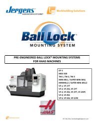
Pre-Engineered Ball Lock ® Fixture Kits for HAAS*<br />
www.jergensinc.com<br />
PRE-MACHINED FIXTURE/SUBPLATES<br />
Ball Lock<br />
Ball Lock ® Mounting System<br />
<strong>Jergens</strong> Introduces Another Piece to the Quick Change Puzzle<br />
Ball Lock ®<br />
Fixture Kits<br />
For HAAS *<br />
HAAS models:<br />
• MINI MILL<br />
• VF-E<br />
• VF-O<br />
• VF-1<br />
• VF-OE<br />
• VF-2<br />
• VF-3<br />
• VF-4<br />
• VF-5<br />
Changes Fixtures in 60 Seconds<br />
Kits for other machine ...or Less<br />
manufacturers available.<br />
Pre-Engineered HAAS Kits<br />
available. PDF Catalog<br />
Available at<br />
www.jergensinc.com<br />
These kits include:<br />
• Steel Subplate with receiver bushings<br />
• Aluminum Fixture Plate(s) with 2 primary liner bushings<br />
• Pre installed receiver and Liner Bushings<br />
• Ball Lock ® Shanks<br />
• T-Slot nuts for mounting subplate to machine table<br />
• 2 Sine Fixture Keys for accurate subplate locating<br />
• Socket head cap screws<br />
Benefits:<br />
• Save time specifying and ordering<br />
• Saves installation time and cost<br />
• Eliminates potential installation errors<br />
Ask about these other machine manufacturers where<br />
Ball Lock ® kits can be utilized.<br />
Call customer support at 1-800-537-4367<br />
Acer<br />
Bridgeport<br />
Brother<br />
Chevalier<br />
Chiron<br />
DMG<br />
Enshu<br />
Excel<br />
Fanuc Robodrill<br />
HAAS<br />
Hardinge<br />
Hitachi<br />
Hitachi Seiki<br />
Hurco<br />
Hyundai-Kia<br />
Johnsford<br />
Kira Mill<br />
Kitamura<br />
Leadwell<br />
MAG<br />
Makino<br />
Matsuura<br />
Mazak<br />
Milltronics<br />
Miyano<br />
Mori-Seiki<br />
OKK<br />
Okuma<br />
Republic Lagun<br />
Toyoda<br />
Tree<br />
YCI<br />
*HAAS is a trademark of HAAS Automation, <strong>Inc</strong>.<br />
1.14<br />
<strong>Jergens</strong>, <strong>Inc</strong>. • <strong>Jergens</strong> Way • 15700 S. Waterloo Road • Cleveland, Ohio 44110-3898 USA
www.jergensinc.com<br />
<strong>BALL</strong> <strong>LOCK</strong> ®<br />
<strong>MOUNTING</strong> <strong>SYSTEM</strong><br />
1<br />
Set-Up Reduction Worksheet<br />
Benefits of Set-Up Reduction (Capacity)<br />
Current Method<br />
Minutes per set-up = minutes<br />
Number of set-ups<br />
per 8 hour shift = set-ups<br />
Total minutes of set-up per shift<br />
(set-up minutes x number of set-ups) = minutes<br />
Using the Ball Lock ® System<br />
Minutes per set-up = minutes<br />
Example (actual case study):<br />
60 minutes<br />
1.5 set-ups<br />
90 minutes<br />
8 minutes<br />
INCH PRE-MACHINED FIXTURE/SUBPLATES<br />
Number of set-ups<br />
per 8 hour shift = set-ups<br />
Total minutes of set-up per shift<br />
(set-up minutes x number of set-ups) = minutes<br />
<strong>Inc</strong>reased capacity per machine per shift<br />
(current method - Ball Lock ® method) = minutes<br />
Savings per machine per shift = minutes<br />
<strong>Inc</strong>reased capacity<br />
(number of minutes / 60) = hours<br />
1.5 set-ups<br />
12 minutes<br />
78 minutes<br />
78 minutes<br />
1.3 hours<br />
Benefits of Set-Up Reduction (Profit)<br />
Machine cost per hour = $ $80.00<br />
<strong>Inc</strong>reased production hours per shift<br />
(increased capacity from above) = hours 1.3 hours<br />
Savings (profit) per machine per shift<br />
(machine cost per hour x increased = $ per machine $104.00 per machine<br />
production hours) per shift per shift<br />
Phone 800-537-4367 or +1 216-486-5540 • Fax: +1 216-481-6193 • E-mail: info@jergensinc.com • www.jergensinc.com 1.15
INCH PRE-MACHINED FIXTURE/SUBPLATES<br />
1 <strong>BALL</strong> <strong>LOCK</strong> ® <strong>MOUNTING</strong> <strong>SYSTEM</strong><br />
INCH DIMENSIONS<br />
Ball Lock ® For 4th Axis Rotary Indexers<br />
Problem:<br />
Rotary indexers increase the versatility of vertical machining<br />
centers, yet they offer one major challenge: set-up is so timeconsuming<br />
that it may limit a machine’s flexibility. In many cases,<br />
machinists dedicate their 4th Axis tool to a single machine to<br />
avoid the agony of an extended set-up and changeover.<br />
Benefits:<br />
• Maximize indexer utilization<br />
• Eliminate lengthy set-ups<br />
• Accurate fixture plate changover in seconds<br />
www.jergensinc.com<br />
Jergen’s Solution:<br />
Ball Lock ® Mounting System for Indexers provides a double<br />
solution.<br />
First, Ball Lock ® mounting plates free up your machine for<br />
additional work by allowing a fast and accurate installation<br />
and removal of the complete indexer. Avoid hours of set up.<br />
The Ball Lock ® System does it in minutes, with repeatability at<br />
±.0005" (±.013mm). Low profile, positive clamping, proven in<br />
over many years of field use.<br />
Second, the Ball Lock ® System provides your fixture plate<br />
changeover. By mounting the round subplate to the indexer<br />
faceplate, you’ll “plug-in” new fixtures in record time<br />
(less than 60 seconds).<br />
Indexer Face Plate<br />
Ball Lock ®<br />
Subplate<br />
Ball Lock ®<br />
Shanks<br />
Ball Lock ®<br />
Fixture Plate<br />
For Holding<br />
Production<br />
Workpiece<br />
Workpiece<br />
Ball Lock ® Fixture Plate<br />
For Mounting Indexer<br />
to Subplate and<br />
Machine Table<br />
Subplates and fixture plates come with bushings pre-installed.<br />
1.16<br />
<strong>Jergens</strong>, <strong>Inc</strong>. • <strong>Jergens</strong> Way • 15700 S. Waterloo Road • Cleveland, Ohio 44110-3898 USA
<strong>BALL</strong> <strong>LOCK</strong> ®<br />
<strong>MOUNTING</strong> <strong>SYSTEM</strong><br />
INCH DIMENSIONS<br />
www.jergensinc.com<br />
Round Ball Lock ® Fixture Plates and Subplates<br />
1<br />
Standard Round<br />
Cast Aluminum, FreeMax or Steel equivalent<br />
Custom Round Plates<br />
Fixture Plate<br />
Part Thickness Ball Lock ® Ball Lock ® Weight<br />
No. A B ±0.005" Liner Shank (lbs)<br />
28707 8" 6" 3/4 16mm 49608 3.5<br />
28708 10" 8" 1 20mm 49602 7.0<br />
28709 12" 10" 1 20mm 49602 11.0<br />
Subplate<br />
Part Thickness Ball Lock ® Center Weight<br />
No. A B ±0.005" Receiver Hole (lbs)<br />
49107 8" 6" 3/4 16mm 1.00" 11.0<br />
49108 10" 8" 1 20mm 2.00" 21.0<br />
49109 12" 10" 1 20mm 2.00" 33.0<br />
Metric sizes also available; please call for information.<br />
INCH PRE-MACHINED FIXTURE/SUBPLATES<br />
Indexer:<br />
Make:<br />
Model:<br />
Diameter:<br />
Light Duty or Heavy Duty:<br />
Through Hole Bore:<br />
CNC Machine:<br />
Make:<br />
Model:<br />
Weight Capacity:<br />
Indexer Faceplate:<br />
T-Slot Size:<br />
Configuration/Orientation:<br />
or<br />
Drilled Tapped Hole Size:<br />
Configuration/Orientation:<br />
Engineering Changes<br />
Product improvement is a continuing process at <strong>Jergens</strong>. Specifications and engineering data are subject to change without notice.<br />
If current information is critical to your design, it is suggested that you contact <strong>Jergens</strong> Technical Sales Department to verify any<br />
dimensions or specifications.<br />
Phone 800-537-4367 or +1 216-486-5540 • Fax: +1 216-481-6193 • E-mail: info@jergensinc.com • www.jergensinc.com 1.17
1 <strong>BALL</strong> <strong>LOCK</strong> ® <strong>MOUNTING</strong> <strong>SYSTEM</strong><br />
INCH DIMENSIONS<br />
www.jergensinc.com<br />
Locating and Clamping Shanks<br />
• Material: Shank/Bushing, 4340<br />
Liner, 52100<br />
• Finish: Black Oxide<br />
• Heat Treat: Shanks, RC 40-45<br />
Bushings, RC 50-54<br />
Liners, RC 62-64<br />
• Operating Temperature Range<br />
-20° to 400°F, -30° to 200°C<br />
D<br />
C<br />
B<br />
Stainless Steel available<br />
A<br />
INCH <strong>BALL</strong> <strong>LOCK</strong> ® COMPONENTS<br />
Ball Lock ® Repair Kits<br />
Each Kit <strong>Inc</strong>ludes:<br />
• Replacement Screw<br />
• Locking Balls<br />
• Drive Ball<br />
• O-Ring<br />
Locating and Clamping Shank Dimensions<br />
Shank<br />
Diameter<br />
(mm)<br />
A<br />
Fixture<br />
Plate<br />
Thickness<br />
± 0.005<br />
Shank<br />
Part<br />
Number<br />
Head of Shank<br />
Height<br />
B<br />
Diameter<br />
C<br />
Length<br />
Under Head<br />
D<br />
Hex Wrench<br />
Size for<br />
Set Screw<br />
Any Ball Lock ® application requires at least two sets of<br />
shanks, receiver bushings and liners. The liners are<br />
placed into the fixture plate to insure extremely accurate<br />
positioning. If more than two shanks are required (to<br />
provide additional hold down force), omit the liner<br />
bushing so that these additional holes will not interfere<br />
with your primary locating holes.<br />
See page 1.20 for Fast Acting Shanks.<br />
Screw<br />
Torque<br />
(Ft/lb)<br />
Maximum<br />
Hold-Down<br />
Force<br />
(lbs)<br />
Recommended<br />
Screw<br />
Torque<br />
(Ft/lb)<br />
Hold-Down<br />
Force<br />
(lbs)<br />
Shank<br />
Repair Kit<br />
Part<br />
Number<br />
13 0.50 49605 0.25 0.87 1.08 3/32 1.2 750 1 625 49905<br />
0.75 49606 1.33 49906<br />
16 0.50 49607 0.32 1.50 1.15 1/8 3 1200 2 800 49907<br />
0.75 49608 1.40 49908<br />
20 0.75 49601 0.38 1.75 1.53 1/8 4 3000 3 2250 49901<br />
1.00 49602 1.78 49902<br />
25 0.75 49611 0.38 2.00 1.70 5/32 9 7000 7 5444 49911<br />
1.00 49612 1.95 49912<br />
30 0.75 49621 0.50 2.25 1.88 3/16 15 10000 12 8000 49921<br />
1.00 49622 2.13 49922<br />
35 0.75 49631 0.50 2.25 1.97 1/4 25 15500 19 11780 49931<br />
1.00 49632 2.22 49932<br />
1.50 49633 2.72 49933<br />
2.00 49634 3.22 49934<br />
50 0.75 49641 0.75 3.00 2.45 3/8 50 20000 38 15200 49941<br />
1.00 49642 2.70 49942<br />
1.50 49643 3.20 49943<br />
2.00 49644 3.70 49944<br />
1.18<br />
<strong>Jergens</strong>, <strong>Inc</strong>. • <strong>Jergens</strong> Way • 15700 S. Waterloo Road • Cleveland, Ohio 44110-3898 USA
www.jergensinc.com<br />
<strong>BALL</strong> <strong>LOCK</strong> ®<br />
<strong>MOUNTING</strong> <strong>SYSTEM</strong><br />
INCH DIMENSIONS<br />
1<br />
Receiver Bushings<br />
Two styles of receiver bushings are available.<br />
Generally, the face mount receiver bushing is<br />
utilized in blind hole applications (Slip Fit).<br />
The back mount receiver bushing is used in<br />
through hole applications (Light Press Fit).<br />
Note: Installed bushings should be approximately<br />
.012" below subplate surface.<br />
See reference below for installation of back mount<br />
style bushings.<br />
Back Mount<br />
Face Mount<br />
Installation Dimensions<br />
Face Mount<br />
Shank<br />
Dia.<br />
(mm)<br />
Face<br />
Mount<br />
Part<br />
Number<br />
Actual<br />
O.D.<br />
+0.0000<br />
-0.0004<br />
Clearance<br />
Drill<br />
Diameter<br />
E<br />
Bore<br />
+0.0005<br />
-0.0000<br />
F<br />
Face Mount Bushing<br />
Installation Instructions<br />
Depth<br />
+0.002<br />
-0.000<br />
G<br />
Tap<br />
Size &<br />
Depth 1<br />
H<br />
13 49506 1.3750 11/16 1.3750 0.469 8-32x5/16 0.984<br />
16 49507 1.4370 13/16 1.4370 0.469 8-32x5/16 1.125<br />
20 49501 1.6873 13/16 1.6873 0.637 10-32x3/8 1.362<br />
25 49502 2.0623 1 2.0623 0.799 1/4-28x1/2 1.644<br />
30 49503 2.2654 1 3/16 2.2654 0.871 1/4-28x3/4 1.876<br />
35 49504 2.6873 1 9/16 2.6873 0.904 5/16-24x7/8 2.178<br />
50 49505 3.4998 2 5/32 3.4998 1.239 3/8-24x1 2.916<br />
Cap Screws Supplied with Face Mount Bushings.<br />
1<br />
Bolt Circle Min.<br />
Diameter Subplate<br />
3 PL Equally Thickness<br />
Spaced D<br />
3/4<br />
3/4<br />
1<br />
1-1/4<br />
1-3/8<br />
1-1/2<br />
2<br />
Back Mount<br />
Shank<br />
Dia.<br />
(mm)<br />
Back Mount Bushing<br />
Installation Instructions<br />
Back<br />
Mount<br />
Part<br />
Number<br />
Actual<br />
O.D.<br />
+0.0000<br />
-0.0004<br />
A<br />
Depth<br />
+0.000<br />
-0.002<br />
B<br />
C-Bore<br />
±0.006<br />
C<br />
13 49516 0.7870 .277 1.000<br />
16 49517 0.8760 .285 1.155<br />
20 49511 1.0950 .345 1.280<br />
25 49512 1.3763 .416 1.593<br />
30 49513 1.6264 .432 1.906<br />
35 49514 1.8764 .493 2.155<br />
50 49515 2.6269 .621 2.988<br />
Min.<br />
Subplate<br />
Thickness<br />
D<br />
3/4<br />
3/4<br />
7/8<br />
1<br />
1-1/4<br />
1-5/16<br />
1-3/4<br />
INCH <strong>BALL</strong> <strong>LOCK</strong> ® COMPONENTS<br />
Liner Bushings for Fixture Plates<br />
Liner Dimensions<br />
Locating repeatability will determine if one primary and one<br />
secondary or two primary liners are needed. With two primary<br />
liners, repeatability of ±.0005" can be maintained if the two<br />
holes for receiver bushings are held to a centerline distance<br />
of ±.0002" tolerance.<br />
Note on Installation of Press Fit Liners &<br />
Back Mount Style Receiver Bushings:<br />
To alleviate the possibility of binding the<br />
shank in the bore, the maximum interference<br />
fit between bore and bushing O.D. should not<br />
exceed .0005".<br />
Fixture Plate<br />
Thickness<br />
±0.005<br />
Shank<br />
Diameter<br />
(mm)<br />
Primary<br />
Liner<br />
Part<br />
Number<br />
Secondary<br />
Liner<br />
Part<br />
Number<br />
Liner O.D.<br />
+0.0000<br />
-0.0004<br />
.50 13 49705 49805 0.7518<br />
.75 13 49706 49806 0.7518<br />
.50 16 49707 49807 1.0018<br />
.75 16 49708 49808 1.0018<br />
.75 20 49701 49801 1.3772<br />
1.00 20 49702 49802 1.3772<br />
.75 25 49711 49811 1.3772<br />
1.00 25 49712 49812 1.3772<br />
.75 30 49721 49821 1.7523<br />
Fixture Plate<br />
Thickness<br />
±0.005<br />
Shank<br />
Diameter<br />
(mm)<br />
Primary<br />
Liner<br />
Part<br />
Number<br />
Secondary<br />
Liner<br />
Part<br />
Number<br />
Liner O.D.<br />
+0.0000<br />
-0.0004<br />
1.00 30 49722 49822 1.7523<br />
.75 35 49731 49831 1.7523<br />
1.00 35 49732 49832 1.7523<br />
1.50 35 49733 49833 1.7523<br />
2.00 35 49734 49834 1.7523<br />
.75 50 49741 49841 2.5025<br />
1.00 50 49742 49842 2.5025<br />
1.50 50 49743 49843 2.5025<br />
2.00 50 49744 49844 2.5025<br />
Phone 800-537-4367 or +1 216-486-5540 • Fax: +1 216-481-6193 • E-mail: info@jergensinc.com • www.jergensinc.com 1.19
1 <strong>BALL</strong> <strong>LOCK</strong> ® <strong>MOUNTING</strong> <strong>SYSTEM</strong><br />
INCH DIMENSIONS<br />
Accessories<br />
www.jergensinc.com<br />
Tapered Caps<br />
and Plugs<br />
Keep debris out<br />
of your subplate’s<br />
receiver bushings<br />
when not in use.<br />
Polyethylene caps<br />
snap in and out easily.<br />
Packaged<br />
10 per<br />
pack.<br />
Receiver<br />
Bushing Part<br />
Diameter Number<br />
13 49201<br />
16 49202<br />
20 49203<br />
25 49204<br />
30 49205<br />
35 49206<br />
50 49207<br />
Lifting Handles<br />
For easy handling of fixture plates up<br />
to 500 lbs.<br />
Part Number Length Ht. W Mounting Distance<br />
33701 4.21 1.42 0.83 3.68<br />
Sine Fixture Keys<br />
INCH <strong>BALL</strong> <strong>LOCK</strong> ® COMPONENTS<br />
Locate subplates or fixture<br />
plates to slotted machine tables<br />
without having to slot the plate.<br />
Available in inch sizes from 1/2"<br />
to 7/8" slots, and in metric sizes<br />
from 14mm to 22mm slots.<br />
NOTE: See page 4.21 for<br />
dimensions.<br />
Fast Acting Ball Lock ® Shanks<br />
B<br />
B<br />
Table<br />
Table Slot<br />
A Slot Size A Size (mm)<br />
Part +0.000 +0.000 Part +0.000 +0.000<br />
Number -0.0005 -0.0005 C Number -0.013 -0.013 C<br />
39501 .625 1/2 1 39562 16 14 1<br />
39502 .625 9/16 1 39563 16 16 1<br />
39503 .625 5/8 1 39564 16 18 1<br />
39504 .625 11/16 1 39565 16 20 1-1/8<br />
39505 .625 3/4 1-1/8 39566 16 22 1-1/8<br />
39506 .625 13/16 1-1/8<br />
39507 .625 7/8 1-1/8<br />
NOTE: All shanks are 5/8" diameter<br />
Fast Acting<br />
Ball Lock ®<br />
Shank<br />
Diameter<br />
(mm)<br />
Fixture<br />
Plate<br />
Thickness<br />
(in.)<br />
<strong>Jergens</strong> Ball Lock ® <strong>Jergens</strong> Ball Lock ®<br />
Shank w/<strong>Jergens</strong><br />
Shank<br />
Thumb Screw<br />
Adjustable Handle<br />
Part Number<br />
Part Number<br />
Assembly T-Screw Assembly Handle<br />
16 1/2 49607-S 43904 49607-H 34314<br />
3/4 49608-S 43904 49608-H 34315<br />
20 3/4 49601-S 43904 49601-H 34315<br />
1 49602-S 43905 49602-H 34316<br />
25 3/4 49611-S 43907 49611-H 34328<br />
1 49612-S 43908 49612-H 34329<br />
30 3/4 49621-S 43910 49621-H 34334<br />
1 49622-S 43911 49622-H 34335<br />
35 3/4 49631-S 43913 49631-H 34339<br />
1 49632-S 43913 49632-H 34339<br />
1-1/2 49633-S 43914 N/A<br />
2 49634-S 43914 N/A<br />
Thumb<br />
Screw<br />
Adjustable<br />
Handle<br />
• Fast acting thumb<br />
screws 2 1/2 turns.<br />
No tools needed.<br />
• Handle can be<br />
moved out of the<br />
work area to avoid<br />
interference.<br />
1.20<br />
<strong>Jergens</strong>, <strong>Inc</strong>. • <strong>Jergens</strong> Way • 15700 S. Waterloo Road • Cleveland, Ohio 44110-3898 USA
www.jergensinc.com<br />
Multi-Purpose Subplate<br />
1000x500 Multi-Purpose Subplate<br />
Part Number Wt. (kg)<br />
59112 130<br />
The <strong>Jergens</strong> Multi-Purpose Subplate<br />
accommodates a wide variety of fixture plates and<br />
vises. This versatility facilitates using the same<br />
VMC for diverse products in repetitive runs-long<br />
and short batch sizes.<br />
<strong>BALL</strong> <strong>LOCK</strong> ®<br />
58706<br />
58801<br />
69406<br />
<strong>MOUNTING</strong> <strong>SYSTEM</strong><br />
METRIC DIMENSIONS<br />
1M<br />
• FreMax TM 15 Steel or Equivalent<br />
• Thickness: 31.75mm ±0.13mm<br />
• Parallel within 0.025mm<br />
58713 or 58715<br />
58727<br />
59112<br />
425 425<br />
300 300<br />
(18) 20MM FACE MOUNT<br />
BUSHINGS I NSTALLED<br />
16MM BORED HOLE<br />
FOR SINE FIXTURE KEYS<br />
(2) PLACES<br />
(8) 25MM FACE MOUNT<br />
BUSHINGS I NSTALLED<br />
Fixture Plate Options for Multi-Purpose Subplates – Aluminum or Steel<br />
1000<br />
Number of Fixture Receiver Required Number<br />
Plates/Vise That Mount Bushing Receiver Ball Lock ® of Shanks<br />
Fixture Plate*/Vise Thickness of on Multi-Purpose Center Bushing Shank Required Per<br />
Part Number Fixture Plate Subplate Distance Size Part Number Fixture Plate/Vise<br />
200<br />
150<br />
300<br />
425<br />
500<br />
METRIC PRE-MACHINED FIXTURE/SUBPLATES<br />
58713 (350 x 350) 20mm 2 300 x 300 20 mm 49651 4<br />
Fixture Plate<br />
58715 (400 x 400) 20mm 2 300 x 300 20 mm 49651 4<br />
Fixture Plate<br />
58801 (400 x 400) 30mm** 2 300 x 300 20 mm 49652 4<br />
Modular Grid Plate<br />
58706 Jigsaw 20mm 4 300 x 200 20 mm 49651 3<br />
Interlocking Plate<br />
58727 (500 x 500) 25mm 2 425 x 425 25 mm 49662 4<br />
Fixture Plate<br />
69406 20mm 4 300 x 200 20 mm 49651 3<br />
150mm Jigsaw Vise<br />
* See next page for dimensional data on fixture plates. Part numbers shown for aluminum plates, also available in steel.<br />
** Counterbored to 25mm at mounting holes.<br />
Phone 800-537-4367 or +1 216-486-5540 • Fax: +1 216-481-6193 • E-mail: info@jergensinc.com • www.jergensinc.com 1.21
1M <strong>BALL</strong> <strong>LOCK</strong> ® <strong>MOUNTING</strong> <strong>SYSTEM</strong><br />
METRIC DIMENSIONS<br />
Fixture Plates for Use on Multi-Purpose Subplate<br />
350x350x20mm Fixture Plate<br />
www.jergensinc.com<br />
400x400 Modular Grid Fixture Plate<br />
Aluminum Plate<br />
Part Number Wt. (kg)<br />
58713 6<br />
Steel Plate<br />
Part Number Wt. (kg)<br />
58813 19<br />
Aluminum Plate<br />
Part Number Wt. (kg)<br />
58801 38<br />
400x400 Fixture Plate<br />
Aluminum Plate<br />
Part Number Wt. (kg)<br />
58715 8<br />
• Cast Aluminum or FreMax 15 Steel or equivalent<br />
• Thickness: 20mm ±0.13mm<br />
• Parallel within 0.025mm Steel<br />
• Mounts to subplates with BallLock ® Shank 49651 (20x20mm)<br />
300<br />
Steel Plate<br />
Part Number Wt. (kg)<br />
58815 25<br />
• FreMax 15 Steel or equivalent<br />
• Thickness: 28.57mm ±0.13mm<br />
• Parallel within 0.025mm Steel<br />
(2) 20MM<br />
PRIMARY LINERS<br />
INSTALLED<br />
CLEARANCE HOLES<br />
FOR HOLDDOWN<br />
(2) PLACES<br />
16MM X 6MM DEEP<br />
COUNTERBORE<br />
M12 X 1.75<br />
TAPPED HOLE<br />
METRIC PRE-MACHINED FIXTURE/SUBPLATES<br />
300<br />
150<br />
CLEARANCE HOLES<br />
FOR HOLDDOWN<br />
(2) PLACES<br />
16MM BORED HOLE<br />
FOR SINE FIXTURE KEYS<br />
(2) PLACES<br />
(2) 20MM<br />
PRIMARY LINERS<br />
INSTALLED<br />
Jigsaw Interlocking FixturePlate<br />
Aluminum Plate<br />
Part Number Wt. (kg)<br />
58706 4<br />
Steel Plate<br />
Part Number Wt. (kg)<br />
58806 12<br />
• Material: Cast Aluminum or FreMax 15 Steel or equivalent<br />
• Thickness: 20mm ±0.13mm<br />
• Parallel within 0.025mm Steel<br />
• For use with narrow base 100mm or 150mm vise models<br />
• Design allows close spacing of vises for more parts per run<br />
• Mounts to Subplates using Ball Lock ® Shank 44651 (20x20mm)<br />
• Useful for high density fixturing<br />
300<br />
400<br />
50<br />
TYP<br />
500x500x25mm Fixture Plate<br />
Aluminum Plate<br />
Part Number Wt. (kg)<br />
58727 17<br />
• Cast Aluminum or FreMax 15 Steel or equivalent<br />
• Thickness: 25mm ±0.13mm<br />
• Parallel within 0.025mm Steel<br />
• Mounts to Subplates using Ball Lock ® Shank 49662 (25x25mm)<br />
500<br />
425<br />
300<br />
400<br />
Mounts to Subplate<br />
with BallLock ® Shank<br />
49652 (20x25mm)<br />
Steel Plate<br />
Part Number Wt. (kg)<br />
58827 48<br />
CLEARANCE HOLE FOR<br />
HOLDDOWN<br />
500 425<br />
CLEARANCE HOLES<br />
FOR HOLDDOWN<br />
(2) PLACES<br />
16MM BORED HOLE<br />
FOR SINE FIXTURE KEYS<br />
(2) PLACES<br />
250<br />
200<br />
(2) 20MM<br />
PRIMARY LINERS<br />
INSTALLED<br />
300<br />
150<br />
200<br />
212.50<br />
(2) 25MM<br />
PRIMARY LINERS<br />
INSTALLED<br />
400<br />
1.22<br />
<strong>Jergens</strong>, <strong>Inc</strong>. • <strong>Jergens</strong> Way • 15700 S. Waterloo Road • Cleveland, Ohio 44110-3898 USA
www.jergensinc.com<br />
<strong>BALL</strong> <strong>LOCK</strong> ®<br />
Pre-Machined Ball Lock ® Steel Subplate<br />
<strong>MOUNTING</strong> <strong>SYSTEM</strong><br />
METRIC DIMENSIONS<br />
1M<br />
400<br />
400 x400 Subplate<br />
300<br />
Part Number Wt. (kg)<br />
59101 37<br />
(4) 20MM<br />
FACE MOUNT BUSHINGS<br />
INSTALLED<br />
Equipped with four 20mm receiver bushings for use with<br />
350x350 or 400x400 (mm) fixture plates. Ideal for horizontal<br />
machining centers or multiple pallet machining centers.<br />
400<br />
300<br />
150<br />
16MM BORED HOLE<br />
FOR SINE FIXTURE KEYS<br />
(2) PLACES<br />
• FreMax 15 steel plate or equivalent<br />
• Thickness: 28.57mm ±0.13mm<br />
• Parallel within 0.025mm<br />
250<br />
25<br />
650<br />
325<br />
650x400 Dual Station Subplate<br />
Part Number Wt. (kg)<br />
59111 58<br />
400<br />
300<br />
150<br />
16MM BORED HOLE<br />
FOR SINE FIXTURE KEYS<br />
(2) PLACES<br />
Aluminum Steel Plate Number Plate<br />
Plate Part Part of Fixture Width and<br />
Number Number Plates Length (mm)<br />
58713 58813 1 350x350<br />
58715 58815 1 400x400<br />
58711 58811 2 300x350<br />
150<br />
300<br />
(12) 20MM<br />
FACE MOUNT BUSHINGS<br />
INSTALLED<br />
Equipped with twelve installed 20mm receiver<br />
bushings to easily locate and mount <strong>Jergens</strong><br />
Standard Fixture Plates.<br />
• Ideal for vertical machining centers<br />
• Thickness: 28.57mm ±0.13mm<br />
• Parallel within 0.025mm<br />
58713 or<br />
58715<br />
58711<br />
59111<br />
METRIC PRE-MACHINED FIXTURE/SUBPLATES<br />
20<br />
˚˚˚<br />
˚<br />
16mm Bored Holes For<br />
Sine Fixture Keys<br />
(2) Places<br />
12mm Dia. For Mounting To<br />
Table (4) Places<br />
(4) 16mm Face Mount<br />
Bushings Installed<br />
300<br />
˚˚˚<br />
63.5<br />
200 250<br />
63.5<br />
˚<br />
250x375 Bridgeport - Style Subplate<br />
Part Number Wt. (kg)<br />
59121 15<br />
Equipped with four installed 16mm receiver bushings and<br />
12mm mounting holes. Used with the Bridgeport style<br />
fixture plates 58731 or 58831.<br />
• Thickness: 19.05mm ±0.13mm<br />
• Parallel within 0.025mm<br />
375<br />
Ball Lock ® Quick Change Kits include all components needed in a single package. See page 1.25 for details.<br />
Phone 800-537-4367 or +1 216-486-5540 • Fax: +1 216-481-6193 • E-mail: info@jergensinc.com • www.jergensinc.com 1.23
1M <strong>BALL</strong> <strong>LOCK</strong> ® <strong>MOUNTING</strong> <strong>SYSTEM</strong><br />
METRIC DIMENSIONS<br />
Ball Lock ® Fixture Plates<br />
• Cast Aluminum; or FreMax 15 Steel or equivalent<br />
• Thickness ±0.13mm<br />
• Parallel within .025mm Steel<br />
• 6061–T-651 plates, flat within 0.03mm available upon request<br />
Ball Lock ® Fixture Plates with 2 Primary Liners Installed<br />
Part Number<br />
Weight<br />
Weight<br />
Aluminum (Kgs) Steel (Kgs)<br />
Plate<br />
Dimensions<br />
(mm)<br />
Plate<br />
Thickness<br />
±0.13(mm)<br />
Ball Lock ®<br />
Shank Size<br />
(mm)<br />
Ball Lock ®<br />
Shank Part<br />
Number<br />
58706 4 58806 12 250 x400 20 20 49651<br />
58711 5 58811 16 300 x350 20 20 49651<br />
58713 6 58813 19 350 x 350 20 20 49651<br />
58715 8 58815 25 400 x 400 20 20 49651<br />
58727 17 58827 48 500 x 500 25 25 49662<br />
58801 38 400 x 400 28.57 20 49652<br />
58731 5 58831 15 375x250 20 16 49657<br />
www.jergensinc.com<br />
• Machined to close tolerances<br />
• Repeatability ±0.013mm or better<br />
• Reduces fixture set-up and<br />
assembly time<br />
• Provided with 16mm bored holes<br />
for sine fixture keys<br />
• For horizontal or vertical<br />
machining centers, Tool Room<br />
Mills machines, or multiple pallet<br />
machining centers<br />
METRIC PRE-MACHINED FIXTURE/SUBPLATES<br />
Custom Sizes Available<br />
<strong>Jergens</strong> will make Ball Lock ® fixture plates or subplates to your<br />
specifications. Call 1-216-486-5540 for further information.<br />
375x250x20mm Fixture Plate Bridgeport Style<br />
Aluminum Plate<br />
Part Number Wt. (kg)<br />
58731 5<br />
Steel Plate<br />
Part Number Wt. (kg)<br />
58831 15<br />
300x350x20mm Fixture Plate<br />
Aluminum Plate<br />
Part Number Wt. (kg)<br />
58711 5<br />
Steel Plate<br />
Part Number Wt. (kg)<br />
58811 16<br />
Clearance Hole For<br />
Holddown (2) Places<br />
300<br />
250<br />
100<br />
16mm Bored Holes For<br />
Sine Fixture Keys<br />
(2) Places<br />
(2) 16mm Primary<br />
Liners Installed<br />
300<br />
375<br />
200<br />
250<br />
350 300<br />
150<br />
Clearance Holes For<br />
Holddown (2) Places<br />
16mm Bored Holes<br />
For Sine Fixture Keys<br />
(2) Places<br />
(2) 20mm Primary<br />
Liners Installed<br />
1.24<br />
<strong>Jergens</strong>, <strong>Inc</strong>. • <strong>Jergens</strong> Way • 15700 S. Waterloo Road • Cleveland, Ohio 44110-3898 USA
www.jergensinc.com<br />
<strong>BALL</strong> <strong>LOCK</strong> ®<br />
<strong>MOUNTING</strong> <strong>SYSTEM</strong><br />
METRIC DIMENSIONS<br />
1M<br />
Quick Change Kits<br />
The <strong>Jergens</strong> Ball Lock ® Quick Change Kits speed fixture changeover in<br />
all types of manufacturing operations. Each kit includes two aluminum<br />
fixture plates with 2 primary liner bushings installed; one steel subplate<br />
with receiver bushings installed, and four 20mm Ball Lock ® shanks<br />
with working loads of 3000 lbs. each. While one fixture plate is on the<br />
machine, the operator can load parts on the other. This minimizes<br />
downtime for true set-up reduction. To enable the subplate to be<br />
mounted on a slotted table without the need to indicate the subplate,<br />
sine fixture keys can be used. The sine fixture key reamed holes are<br />
oriented parallel to the receiver bushings on the subplate and to the<br />
liner bushings on the fixture plate. These also allow the fixture plate<br />
to be mounted on a toolroom mill<br />
without the need to indicate it. This<br />
is extremely useful when machining<br />
location points on your fixture.<br />
Everything You Need to Change Fixtures in Less Than One Minute<br />
Aluminum<br />
Fixture Plate<br />
16mm Bored<br />
Hole for Sine<br />
Fixture Keys<br />
20mm Ball Lock ®<br />
Shank<br />
Quick Change Kits<br />
Part No.<br />
Kit <strong>Inc</strong>ludes<br />
59002 2 - 58715 (400x400x20) aluminum<br />
fixture plates with 20mm liner<br />
bushings installed<br />
1 - 59101 (400x400x25) steel subplate<br />
with receiver bushings installed<br />
4 - 20mm Ball Lock ® Shanks (49651)<br />
METRIC PRE-MACHINED FIXTURE/SUBPLATES<br />
Steel Subplate<br />
16mm Bored<br />
Hole for Sine<br />
Fixture Keys<br />
(2) 20mm Primary Liner<br />
Bushings Installed<br />
(4) 20mm<br />
Receiver<br />
Bushings<br />
Installed<br />
Custom Kits Available<br />
<strong>Jergens</strong> manufactures ready to use kits including<br />
Ball Lock ® subplate and fixture plates.<br />
For a special kit tailored to your CNC machine,<br />
please provide:<br />
Name and Type of Machine __________________<br />
Travel of Machine Table (x, y, z) ______________<br />
Dimensions of Machine Table (x and y) _________<br />
Maximum Weight allowed on Machine Table _____<br />
T-slot Width and Center to Center Distance _____<br />
Phone 800-537-4367 or +1 216-486-5540 • Fax: +1 216-481-6193 • E-mail: info@jergensinc.com • www.jergensinc.com 1.25
1M <strong>BALL</strong> <strong>LOCK</strong> ® <strong>MOUNTING</strong> <strong>SYSTEM</strong><br />
METRIC DIMENSIONS<br />
Pre-Machined Ball Lock ® T-Columns<br />
• Class 40 Cast Iron<br />
• Also available in Aluminum<br />
• Ball Lock ® Receiver Bushings and Liners installed<br />
• Provides accurate fixturing base for CNC machining centers<br />
• Perpendicularity is 0.025 mm per 250 mm<br />
www.jergensinc.com<br />
Fixture<br />
Plate<br />
Custom Sizes Available with or without Ball Lock ®<br />
We are able to quote you on your special requirement<br />
with or without the Ball Lock ® Mounting System.<br />
Call 1-216-486-5540 for design specification information.<br />
Subplate<br />
Tooling<br />
Column<br />
METRIC PRE-MACHINED TOOLING COLUMNS<br />
Cast Iron T-Columns With<br />
Ball Lock ® Receiver Bushings Installed<br />
Pallet Part O P Wt.<br />
Size (mm) Number C D E F G H I J K L M N (mm) (mm) (kg)<br />
400 69151 410 25 400 400 350 350 350 350 100 500 125 90 20 20 190<br />
500 69161 560 25 500 500 475 425 425 425 120 650 137.5 90 25 25 310<br />
630 69171 660 40 630 630 575 550 525 525 100 750 137.5 90 35 25 500<br />
M12<br />
See page 1.28 for Metric Fixture Plates and Subplates<br />
*Note: Window sections are also available on T-Columns. Specify window size and location (Q and R Dimensions).<br />
Corresponding Fixture Plates, Subplates and Ball Lock ® Shanks<br />
Pallet T-Column Aluminum Steel Fixture Fixture Plate Subplate<br />
Size Part Fixture Plate Fixture Plate Plate Ball Lock ® Shank Shank Subplate Ball Lock ® Shank Shank<br />
(mm) Number Part Number Part Number Size Part Number Size Part Number Part Number Size<br />
400 69151 58717 58817 400 x 400 49651 20 x 20 59102 49652 20 x 25<br />
500 69161 58745 58845 500 x 550 49662 25 x 25 59103 49662 25 x 25<br />
630 69171 58746 58846 625 x 650 49662 25 x 25 59104 49683 35 x 40<br />
Use Hoist Ring 23462, see page 11.9 for lifting and handling – Order separately.<br />
Engineering Changes<br />
Product improvement is a continuing process at <strong>Jergens</strong>. Specifications and engineering data are subject to change<br />
after publishing. Contact <strong>Jergens</strong> Technical Sales Department to verify any dimensions or specifications.<br />
1.26<br />
<strong>Jergens</strong>, <strong>Inc</strong>. • <strong>Jergens</strong> Way • 15700 S. Waterloo Road • Cleveland, Ohio 44110-3898 USA
www.jergensinc.com<br />
<strong>BALL</strong> <strong>LOCK</strong> ®<br />
<strong>MOUNTING</strong> <strong>SYSTEM</strong><br />
METRIC DIMENSIONS<br />
1M<br />
Pre-Machined Ball Lock ® 4-Sided Tooling Columns<br />
• Class 40 cast iron<br />
• Also available in Aluminum<br />
• Ball Lock ® Receiver Bushings and Liner Bushings installed<br />
• Provides accurate fixturing base for CNC machining centers<br />
• Perpendicularity is 0.025 mm per 250 mm<br />
Tooling<br />
Column<br />
Fixture<br />
Plate<br />
Custom Sizes Available with or without Ball Lock ®<br />
We are able to quote you on your special requirement<br />
with or without the Ball Lock ® Mounting System.<br />
Call 1-216-486-5540 for design specification information.<br />
Subplate<br />
Cast Iron 4-Sided Tooling Columns With<br />
Ball Lock ® Receiver Bushings Installed<br />
See page 1.26 for Metric Fixture and Subplates<br />
Pallet Part O P Wt.<br />
Size (mm) Number A B C D E F G H I J K L M N (mm) (mm) (kg)<br />
400 69051 250 250 505 25 400 400 450 150 350 350 40 600 125 95 20 20 225<br />
500 69061 300 300 630 25 500 500 550 175 425 425 40 725 137.5 95 25 25 320<br />
630 69071 400 400 655 40 630 630 575 275 525 525 45 750 137.5 95 35 25 495<br />
M12<br />
METRIC PRE-MACHINED TOOLING COLUMNS<br />
Corresponding Fixture Plates, Subplates and Ball Lock ® Shanks<br />
Pallet T-Column Aluminum Steel Fixture Fixture Plate Subplate<br />
Size Part Fixture Plate Fixture Plate Plate Ball Lock ® Shank Shank Subplate Ball Lock ® Shank Shank<br />
(mm) Number Part Number Part Number Size Part Number Size Part Number Part Number Size<br />
400 69051 58741 58841 250 x 500 49651 20 x 20 59102 49652 20 x 25<br />
500 69061 58742 58842 300 x 625 49662 25 x 25 59103 49662 25 x 25<br />
630 69071 58743 58843 400 x 650 49662 25 x 25 59104 49683 35 x 40<br />
Use Hoist Ring 23462, see page 11.9 for lifting and handling – Order separately.<br />
Engineering Changes<br />
Product improvement is a continuing process at <strong>Jergens</strong>. Specifications and engineering data are subject to<br />
change after publishing. Contact <strong>Jergens</strong> Technical Sales Department to verify any dimensions or specifications.<br />
Phone 800-537-4367 or +1 216-486-5540 • Fax: +1 216-481-6193 • E-mail: info@jergensinc.com • www.jergensinc.com 1.27
1M <strong>BALL</strong> <strong>LOCK</strong> ® <strong>MOUNTING</strong> <strong>SYSTEM</strong><br />
METRIC DIMENSIONS<br />
Subplates for Tooling Columns and Fixture Plates<br />
16mm Bored holes<br />
for sine fixture<br />
keys (2) places<br />
Receiver<br />
Bushings<br />
A<br />
B<br />
Standard Steel Subplates for Tooling Columns<br />
Subplate Mounting holes can be provided per customer specification.<br />
Supplied with Ball Lock ® Receiver Bushings installed.<br />
www.jergensinc.com<br />
Ball Lock ® Pattern Receiver Thickness of<br />
Part Pallet Size For Tooling A B Size Subplate Wt<br />
Number (mm) Columns (mm) (mm) (mm) (mm) ±0.13 (Kgs)<br />
59102 400 69151/69051 350 350 20 28.57 31<br />
59103 500 69161/69061 425 425 25 31.75 59<br />
59103-C* 500 69151, 69051 350/425 350/425 20/25 31.75 59<br />
69161, 69061 Dual Dual Dual<br />
59104 630 69171/69071 525 525 35 34.92 124<br />
METRIC PRE-MACHINED FIXTURE/SUBPLATES<br />
16mm Bored holes<br />
for sine fixture keys<br />
(2) places<br />
Primary<br />
Liners<br />
16mm Bored holes<br />
for sine fixture keys<br />
(2) places<br />
J<br />
E<br />
Primary<br />
Liners<br />
Fixture Plates for Standard Tooling Columns and T-Columns<br />
Supplied with 2 primary Ball Lock ® Liner Bushings installed.<br />
Fixture Fixture Plate Ball Lock ® Pattern Liner<br />
Pallet Part Number For Tooling Plate Size Thickness H G Size<br />
Size (mm) Aluminum (kg) Steel (kg) Columns Type (mm) (mm) ±0.13 (mm) (mm) (mm)<br />
400 58741 7 58841 19 69051 4-S 250x500 150 450 20 20<br />
I<br />
500 58742 13 58842 36 69061 4-S 300x625 175 550 25 25<br />
630 58743 18 58843 50 69071 4-S 400x650 275 575 25 25<br />
400 58717 8 58817 25 69151 T 400x400 350 350 20 20<br />
500 58745 19 58845 53 69161 T 500x550 425 475 25 25<br />
630 58746 27 58846 63 69171 T 625x650 550 575 25 25<br />
F<br />
Fixture Plates for Tooling Column Subplates<br />
Supplied with 2 primary Ball Lock ® Liner Bushings installed.<br />
Ball Lock ®<br />
Pallet Part Number Plate Dim. Fixture Plate Pattern Liner<br />
Size For E F Thickness I J Size<br />
(mm) Aluminum (kg) Steel (kg) Subplate (mm) (mm) ±0.13 (mm) (mm) (mm) (mm)<br />
400 58717 8 58817 25 59102 400 400 20 350 350 20<br />
500 58727 17 58827 48 59103 500 500 25 425 425 25<br />
630 58732 27 58832 76 59104 630 630 25 525 525 35<br />
Difference between Aluminum and Steel<br />
( mm )<br />
0.0015<br />
0.00125<br />
0.001<br />
0.00075<br />
0.0005<br />
0.00025<br />
0<br />
0<br />
Aluminum and Steel Expansion<br />
(per cm )<br />
2.8 5.4 8.4 11.2 14 16.8<br />
Change in Degrees C<br />
NOTE: Aluminum and steel expand at different rates. Please take this information into consideration<br />
when creating your own Ball Lock ® fixture and subplates.<br />
1.28<br />
<strong>Jergens</strong>, <strong>Inc</strong>. • <strong>Jergens</strong> Way • 15700 S. Waterloo Road • Cleveland, Ohio 44110-3898 USA
www.jergensinc.com<br />
<strong>BALL</strong> <strong>LOCK</strong> ®<br />
Ball Lock® For 4th Axis Rotary Indexers<br />
Problem:<br />
Rotary indexers increase the versatility of vertical machining<br />
centers, yet they offer one major challenge: set-up is so timeconsuming<br />
that it may limit a machine’s flexibility. In many cases,<br />
machinists dedicate their 4th Axis tool to a single machine to<br />
avoid the agony of an extended set-up and changeover.<br />
Benefits:<br />
• Maximize indexer utilization<br />
• Eliminate lengthy set-ups<br />
• Accurate fixture plate changover in seconds<br />
<strong>MOUNTING</strong> <strong>SYSTEM</strong><br />
METRIC DIMENSIONS<br />
1M<br />
Jergen’s Solution:<br />
Ball Lock ® Mounting System for Indexers provides a double<br />
solution.<br />
First, Ball Lock ® mounting plates free up your machine for<br />
additional work by allowing a fast and accurate installation<br />
and removal of the complete indexer. Avoid hours of set up.<br />
The Ball Lock ® System does it in minutes, with repeatability at<br />
±.0005" (±.013mm). Low profile, positive clamping, proven in<br />
over many years of field use.<br />
Second, the Ball Lock ® System provides your fixture plate<br />
changeover. By mounting the round subplate to the indexer<br />
faceplate, you’ll “plug-in” new fixtures in record time<br />
(less than 60 seconds).<br />
Indexer Face Plate<br />
Ball Lock ®<br />
Fixture Plate<br />
For Holding<br />
Production<br />
Workpiece<br />
Ball Lock ®<br />
Shanks<br />
Ball Lock ®<br />
Subplate<br />
METRIC PRE-MACHINED FIXTURE/SUBPLATES<br />
Workpiece<br />
Ball Lock ® Fixture Plate<br />
For Mounting Indexer<br />
to Subplate and<br />
Machine Table<br />
Subplates and fixture plates come with bushings pre-installed.<br />
Phone 800-537-4367 or +1 216-486-5540 • Fax: +1 216-481-6193 • E-mail: info@jergensinc.com • www.jergensinc.com 1.29
1M <strong>BALL</strong> <strong>LOCK</strong> ® <strong>MOUNTING</strong> <strong>SYSTEM</strong><br />
METRIC DIMENSIONS<br />
www.jergensinc.com<br />
Round Ball Lock ® Fixture Plates and Subplates<br />
Standard Round<br />
Cast Aluminum, FreeMax or Steel equivalent<br />
Fixture Plate (mm)<br />
Part Ball Lock ® Ball Lock ® Weight<br />
No. A B Thickness Liner Shank (Kgs)<br />
58707 200 150 20 16 49657 1.6<br />
58708 250 200 25 20 49652 3.2<br />
58709 300 250 25 20 49652 5.0<br />
Subplate(mm)<br />
Part Ball Lock ® Center Weight<br />
No. A B Thickness Receiver Hole (Kgs)<br />
59107 200 150 20 16 25 5.0<br />
59108 250 200 25 20 50 9.6<br />
59109 300 250 25 20 50 15.0<br />
Note: Equivalent system available in inch dimensions.<br />
Custom Round Plates<br />
METRIC PRE-MACHINED FIXTURE/SUBPLATES<br />
Indexer:<br />
Make:<br />
Model:<br />
Diameter:<br />
Light Duty or Heavy Duty:<br />
Through Hole Bore:<br />
CNC Machine:<br />
Make:<br />
Model:<br />
Weight Capacity:<br />
Indexer Faceplate:<br />
T-Slot Size:<br />
Configuration/Orientation:<br />
or<br />
Drilled Tapped Hole Size:<br />
Configuration/Orientation:<br />
Engineering Changes<br />
Product improvement is a continuing process at <strong>Jergens</strong>. Specifications and engineering data are subject to change without<br />
notice. If current information is critical to your design, it is suggested that you contact <strong>Jergens</strong> Technical Sales Department to<br />
verify any dimensions or specifications.<br />
1.30<br />
<strong>Jergens</strong>, <strong>Inc</strong>. • <strong>Jergens</strong> Way • 15700 S. Waterloo Road • Cleveland, Ohio 44110-3898 USA
www.jergensinc.com<br />
<strong>BALL</strong> <strong>LOCK</strong> ®<br />
Locating and Clamping Shanks<br />
<strong>MOUNTING</strong> <strong>SYSTEM</strong><br />
METRIC DIMENSIONS<br />
1M<br />
U.S. Patents: 3,498,653<br />
4,135,418<br />
Replacement Kits<br />
Locating and Clamping Shank Dimensions<br />
Shank<br />
Diameter<br />
(mm)<br />
A<br />
13<br />
16<br />
20<br />
25<br />
30<br />
35<br />
50<br />
Fixture<br />
Plate<br />
Thickness<br />
±0.13mm<br />
13<br />
20<br />
20<br />
25<br />
20<br />
25<br />
20<br />
25<br />
20<br />
25<br />
20<br />
25<br />
40<br />
50<br />
20<br />
25<br />
40<br />
50<br />
• Material: Shank/Bushing, AISI 4340<br />
Liner, 52100<br />
• Finish: Black Oxide<br />
• Heat Treat: Shanks, RC 40-45<br />
Bushings, RC 50-54<br />
Liners, RC 62-64<br />
• Operating Temperature Range:<br />
-30°C to 200°C<br />
• Stainless Steel available<br />
Head of Shank<br />
Shank<br />
Part<br />
Height Diameter<br />
Number B C D<br />
49655<br />
49656<br />
49657<br />
49658<br />
49651<br />
49652<br />
49661<br />
49662<br />
49671<br />
49672<br />
49681<br />
49682<br />
49683<br />
49684<br />
49691<br />
49692<br />
49693<br />
49694<br />
6<br />
8<br />
10<br />
10<br />
13<br />
13<br />
20<br />
22<br />
32<br />
40<br />
45<br />
50<br />
60<br />
75<br />
Each Kit <strong>Inc</strong>ludes:<br />
• Replacement Screw<br />
• Locking Balls<br />
• Drive Ball<br />
• O-Ring<br />
27.6<br />
34.6<br />
36.5<br />
41.5<br />
39.5<br />
44.5<br />
44.0<br />
49.0<br />
49.0<br />
54.0<br />
51.0<br />
56.0<br />
71.0<br />
81.0<br />
64.0<br />
69.0<br />
84.0<br />
94.0<br />
Hex<br />
Wrench Size<br />
For<br />
Set Screw<br />
2.5<br />
3<br />
3<br />
4<br />
5<br />
6<br />
10<br />
D<br />
C<br />
A<br />
Any Ball Lock ® application requires at least two sets of<br />
shanks, receiver bushings and liners. The liners are<br />
placed into the fixture plate to insure extremely accurate<br />
positioning. If more than two shanks are required (to<br />
provide additional hold down force), omit the liner bushing<br />
so that these additional holes will not interfere with your<br />
primary locating holes.<br />
See page 1.33 for Fast Acting Shanks.<br />
Maximum<br />
Screw Holddown<br />
Torque Force<br />
(N.m) (KN)<br />
1.2 3.3<br />
4.5<br />
5.3<br />
11<br />
18<br />
33<br />
65<br />
5.3<br />
13.3<br />
30<br />
44<br />
68<br />
88<br />
B<br />
Recommended<br />
Screw Holddown<br />
Torque Force<br />
(N.m) (KN)<br />
1 2.7<br />
3<br />
4<br />
9<br />
15<br />
25<br />
50<br />
3.5<br />
10<br />
23<br />
35<br />
52<br />
67<br />
Shank<br />
Repair Kit<br />
Part<br />
Number<br />
49955<br />
49956<br />
49957<br />
49958<br />
49951<br />
49952<br />
49961<br />
49962<br />
49971<br />
49972<br />
49981<br />
49982<br />
49983<br />
49984<br />
49991<br />
49992<br />
49993<br />
49994<br />
METRIC <strong>BALL</strong> <strong>LOCK</strong> ® COMPONENTS<br />
Phone 800-537-4367 or +1 216-486-5540 • Fax: +1 216-481-6193 • E-mail: info@jergensinc.com • www.jergensinc.com 1.31
1M <strong>BALL</strong> <strong>LOCK</strong> ® <strong>MOUNTING</strong> <strong>SYSTEM</strong><br />
METRIC DIMENSIONS<br />
Receiver Bushings<br />
www.jergensinc.com<br />
Two styles of receiver bushings are available. Installed bushings should be approximately 0.3mm below subplate surface.<br />
Max. Corner<br />
Radius 0.5mm<br />
Face Mount<br />
Back Mount<br />
Max. Corner<br />
Radius 0.5mm<br />
H - Tap 3 Holes<br />
Equally Spaced<br />
On Bolt Circle Dia.<br />
Face Mount Bushing<br />
Installation Instructions<br />
Back Mount Bushing<br />
Installation Instructions<br />
METRIC <strong>BALL</strong> <strong>LOCK</strong> ® COMPONENTS<br />
Generally, the face mount receiver bushing is utilized in blind hole<br />
applications (Slip Fit).<br />
Installation Dimensions<br />
Face Mount<br />
Shank<br />
Dia.<br />
(mm)<br />
13<br />
16<br />
20<br />
25<br />
30<br />
35<br />
50<br />
Face<br />
Mount<br />
Part<br />
Number<br />
49556<br />
49557<br />
49551<br />
49552<br />
49553<br />
49554<br />
49555<br />
Actual<br />
O.D.<br />
-0.01<br />
-0.02<br />
35<br />
37<br />
45<br />
55<br />
60<br />
70<br />
92<br />
Clearance<br />
Drill<br />
Diameter<br />
E<br />
13.5<br />
21.0<br />
21.0<br />
25.5<br />
30.5<br />
40.0<br />
55.0<br />
Bore<br />
+0.010<br />
+0.003<br />
F<br />
35<br />
37<br />
45<br />
55<br />
60<br />
70<br />
92<br />
1<br />
Cap Screws Supplied with Face Mount Bushings.<br />
Liner Bushings for<br />
Fixture Plates<br />
Depth<br />
+0.025<br />
-0.025<br />
G<br />
11.91<br />
11.91<br />
16.21<br />
20.32<br />
22.15<br />
22.99<br />
31.50<br />
Note on Installation of Press Fit Liners &<br />
Back Mount Style Receiver Bushings:<br />
To alleviate the possibility of binding the<br />
shank in the bore, the maximum interference<br />
fit between bore and bushing O.D. should not<br />
exceed 0.013 mm.<br />
Tap<br />
Size &<br />
Depth 1<br />
H<br />
M4x0.7 x 7<br />
M4x0.7 x 7<br />
M5x0.8 x 9<br />
M6x1.0 x 10<br />
M6x1.0 x 11<br />
M8x1.25 x 17<br />
M10x1.5 x 18<br />
Locating repeatability will determine if one primary<br />
and one secondary or two primary liners are needed.<br />
With two primary liners, repeatability of ±0.013 mm can<br />
be maintained if the two holes for receiver bushings are<br />
held to a centerline distance of ±0.005 mm tolerance.<br />
Bolt Circle<br />
Diameter<br />
3 PL Equally<br />
Spaced<br />
25<br />
29<br />
35<br />
42<br />
48<br />
56<br />
75<br />
Min.<br />
Subplate<br />
Thickness<br />
D<br />
20<br />
20<br />
25<br />
30<br />
35<br />
40<br />
50<br />
Liner Dimensions<br />
Shank<br />
Diameter<br />
(mm)<br />
13<br />
16<br />
20<br />
25<br />
30<br />
35<br />
50<br />
Fixture Plate<br />
Thickness<br />
+0.13<br />
- 0.13<br />
13<br />
20<br />
20<br />
25<br />
20<br />
25<br />
20<br />
25<br />
20<br />
25<br />
20<br />
25<br />
40<br />
50<br />
20<br />
25<br />
40<br />
50<br />
The back mount receiver bushing is used in through hole<br />
applications (Light Press Fit).<br />
Back Mount<br />
Shank<br />
Dia.<br />
(mm)<br />
13<br />
16<br />
20<br />
25<br />
30<br />
35<br />
50<br />
49755<br />
49756<br />
49757<br />
49758<br />
49751<br />
49752<br />
49761<br />
49762<br />
49771<br />
49772<br />
49781<br />
49782<br />
49783<br />
49784<br />
49791<br />
49792<br />
49793<br />
49794<br />
Back<br />
Mount<br />
Part<br />
Number<br />
49566<br />
49567<br />
49561<br />
49562<br />
49563<br />
49564<br />
49565<br />
Primary Liner<br />
Part Number<br />
I.D.<br />
13.01<br />
16.01<br />
20.01<br />
25.01<br />
30.01<br />
35.01<br />
50.01<br />
Actual<br />
O.D.<br />
+0.04<br />
+0.03<br />
A<br />
20<br />
22<br />
28<br />
35<br />
42<br />
48<br />
67<br />
49855<br />
49856<br />
49857<br />
49858<br />
49851<br />
49852<br />
49861<br />
49862<br />
49871<br />
49872<br />
49881<br />
49882<br />
49883<br />
49884<br />
49891<br />
49892<br />
49893<br />
49894<br />
Depth<br />
+0.025<br />
-0.025<br />
B<br />
6.92<br />
7.24<br />
8.74<br />
10.54<br />
10.95<br />
12.50<br />
15.75<br />
Secondary Liner<br />
Part Number<br />
I.D.<br />
13.04<br />
16.04<br />
20.04<br />
25.04<br />
30.04<br />
35.04<br />
50.04<br />
C-Bore<br />
± 0.15<br />
C<br />
26<br />
29<br />
33<br />
41<br />
49<br />
55<br />
76<br />
Min.<br />
Subplate<br />
Thickness<br />
D<br />
20<br />
20<br />
25<br />
25<br />
30<br />
35<br />
45<br />
Liner O.D.<br />
+0.00<br />
- 0.01<br />
19.040<br />
19.040<br />
25.042<br />
25.042<br />
35.042<br />
35.042<br />
35.042<br />
35.042<br />
45.042<br />
45.042<br />
45.042<br />
45.042<br />
45.042<br />
45.042<br />
63.546<br />
63.546<br />
63.546<br />
63.546<br />
1.32<br />
<strong>Jergens</strong>, <strong>Inc</strong>. • <strong>Jergens</strong> Way • 15700 S. Waterloo Road • Cleveland, Ohio 44110-3898 USA
www.jergensinc.com<br />
Accessories<br />
Tapered Caps<br />
and Plugs<br />
Keep debris out of your<br />
subplate’s receiver<br />
bushings when not in<br />
use. Polyethylene caps<br />
snap in and out easily.<br />
Packaged<br />
10 per<br />
pack.<br />
<strong>BALL</strong> <strong>LOCK</strong> ®<br />
Receiver<br />
Bushing Part<br />
Diameter Number<br />
13 49201<br />
16 49202<br />
20 49203<br />
25 49204<br />
30 49205<br />
35 49206<br />
50 49207<br />
<strong>MOUNTING</strong> <strong>SYSTEM</strong><br />
METRIC DIMENSIONS<br />
Lifting Handles<br />
For easy handling of fixture plates up<br />
to 500 lbs.<br />
1M<br />
Part Number Length Ht. W Mounting Distance<br />
33701 107mm 36mm .38kg 93.47mm<br />
Sine Fixture Keys<br />
Shank Slot<br />
Part Size Size Wt.<br />
Number A B C (kg)<br />
39551 16 12 25 .04<br />
39552 16 14 25 .05<br />
39553 16 16 25 .05<br />
39554 16 18 29 .05<br />
39555 16 20 29 .06<br />
39556 16 22 29 .06<br />
39557 20 24 35 .07<br />
39558 20 28 35 .10<br />
39559 20 32 40 .10<br />
Recommended<br />
Hole Diameter<br />
16mm Shank Size:<br />
16.01 ± 0.01<br />
20mm Shank Size:<br />
20.01 ± 0.01<br />
Locate subplates or fixture plates to<br />
slotted machine tables without having<br />
to slot the plate. Available in sizes from<br />
12mm to 32mm slots.<br />
METRIC <strong>BALL</strong> <strong>LOCK</strong> ® COMPONENTS<br />
Fast Acting Ball Lock ® Shanks<br />
Fast Acting Ball Lock ® Shanks<br />
Ball Lock ®<br />
Shank<br />
Diameter<br />
(mm)<br />
Fixture<br />
Plate<br />
Thickness<br />
(mm)<br />
Shank with<br />
Thumb Screw<br />
Shank with<br />
Adjustable Handle<br />
Part Number<br />
Part Number<br />
Assenbly T-Screw Assenbly Handle<br />
13 13 49655-S 43971 49655-H 34360<br />
20 49656-S 43972 49656-H 34361<br />
16 20 49657-S 43974 49657-H 34365<br />
25 49658-S 43975 49658-H 34365<br />
20 20 49651-S 43974 49651-H 34365<br />
25 49652-S 43975 49652-H 34365<br />
25 20 49661-S 43977 49661-H 34378<br />
25 49662-S 43978 49662-H 34379<br />
30 20 49671-S 43980 49671-H 34385<br />
25 49672-S 43980 49672-H 34385<br />
35 20 49681-S 43985 49681-H 34393<br />
25 49682-S 43985 49682-H 34393<br />
Thumb<br />
Screw<br />
Adjustable<br />
Handle<br />
• Fast acting thumb<br />
screws 2 1/2 turns.<br />
No tools needed.<br />
• Handle can be<br />
moved out of the<br />
work area to avoid<br />
interference.<br />
Phone 800-537-4367 or +1 216-486-5540 • Fax: +1 216-481-6193 • E-mail: info@jergensinc.com • www.jergensinc.com 1.33
1 ZERO POINT <strong>MOUNTING</strong> <strong>SYSTEM</strong><br />
Features of the <strong>Jergens</strong> Zero-Point Mounting System<br />
• Positioning and clamping in one operation<br />
• High repeatability and accuracy<br />
• Low cost solution for quick pallet changing<br />
www.jergensinc.com<br />
Typical applications for the<br />
<strong>Jergens</strong> Zero-Point System:<br />
• Milling<br />
• Assembly<br />
• Welding<br />
• Injection Molding<br />
• Grinding<br />
• Measuring<br />
Pull Studs can also be<br />
installed directly into the<br />
workpieces, making 5-sided<br />
processing possible.<br />
Best results with large and<br />
heavy workpieces.<br />
<strong>Jergens</strong> Zero-Point clamping<br />
systems are made exclusively<br />
of rust-free materials and so<br />
are ideally suited for use in<br />
the food-service area as well<br />
as in the pharmaceutical and<br />
chemical industry.<br />
Through different dimensions,<br />
the advantage of the Zero-<br />
Point clamping system are<br />
optimally used.<br />
1.36<br />
<strong>Jergens</strong>, <strong>Inc</strong>. • <strong>Jergens</strong> Way • 15700 S. Waterloo Road • Cleveland, Ohio 44110-3898 USA
www.jergensinc.com<br />
ZERO POINT <strong>MOUNTING</strong> <strong>SYSTEM</strong><br />
1<br />
Pull Studs and Engagement Screws<br />
Pages 1.42-1.43<br />
Clamping Plates with Built-In Modules<br />
Pages 1.40-1.41<br />
Threaded Clamping Modules<br />
Pages 1.44-1.45<br />
• Machine tables<br />
• Plates<br />
• 4-axis/5-axis machining<br />
• Columns<br />
• Pallets<br />
Raised/Mounted Clamping Modules<br />
Pages 1.46-1.47<br />
• For large & heavy workpieces<br />
• Pull Studs installed<br />
directly into workpiece<br />
Flange Type Module<br />
Page 1.49<br />
• Used to fasten surface-mounted clamping modules<br />
on the machine table<br />
• Hydraulic release with or without blowout<br />
Horizontal Rapid-Clamping Module<br />
Page 1.50<br />
• For easy handling of heavy fixtures<br />
Phone 800-537-4367 or +1 216-486-5540 • Fax: +1 216-481-6193 • E-mail: info@jergensinc.com • www.jergensinc.com 1.37
1 ZERO POINT <strong>MOUNTING</strong> <strong>SYSTEM</strong><br />
<strong>Jergens</strong>’ Zero-Point Mounting System –<br />
Cut Set-up Times by Up to 90%.<br />
Fix, Position and Clamp in a Single Step with<br />
<strong>Jergens</strong>’ Zero-Point Mounting System.<br />
www.jergensinc.com<br />
<strong>Jergens</strong> is proud to introduce the best-engineered Zero-Point<br />
Mounting System (ZPS) on the market. This revolutionary<br />
technology cuts set-up time by up to 90% by combining fixing,<br />
positioning and clamping in a single operation. Available with<br />
either pneumatic or hydraulic release, these positive locking<br />
locating modules allow operators to quickly change out large<br />
and small machine fixtures with extreme accuracy and minimal<br />
effort. Other features include:<br />
• Repeatability
www.jergensinc.com<br />
ZERO POINT <strong>MOUNTING</strong> <strong>SYSTEM</strong><br />
1<br />
Mechanical Locking System<br />
Experience high holding force without the need to maintain<br />
hydraulic pressure.<br />
Large Ball Diameter<br />
Provides increased strength and even load distribution.<br />
No Ball Cage<br />
Free movement of the bearing balls reduces friction.<br />
Form Fit Ball Channel<br />
Tapered contact areas eliminate point loads and<br />
reduce failures.<br />
Three-Point Load Distribution<br />
Equal load spacing optimizes force distribution.<br />
Integrated Safety System<br />
Process-sure clamping module can always be opened,<br />
eliminating the need to forcibly remove modules if a failure<br />
should occur.<br />
Phone 800-537-4367 or +1 216-486-5540 • Fax: +1 216-481-6193 • E-mail: info@jergensinc.com • www.jergensinc.com 1.39
1 ZERO POINT <strong>MOUNTING</strong> <strong>SYSTEM</strong><br />
Clamping and Positioning<br />
www.jergensinc.com<br />
On each fixture use:<br />
• 1 - Zero-Point Pull Stud<br />
• 1 - Timing Pull Stud<br />
• The Zero-Point and Timing Stud should<br />
be perpendicular<br />
• Use any combination of clearance and/or<br />
protection Pull Stud<br />
ZERO POINT PULL STUD<br />
CLEARANCE PULL STUD<br />
FOR HOLD DOWN<br />
CLEARANCE PULL STUD<br />
FOR HOLD DOWN<br />
TIMING PULL STUD<br />
Dimensions for machining pull stud mountings<br />
Size ØD1 ØM S1 S2<br />
K5 10 M6 2.5 12<br />
K10 15 M8 3.5 16<br />
K20 25 M12 5.5 23<br />
K40 25 M16 5.5 30<br />
Note:<br />
• Pull Stud with internal thread for clamping from above<br />
• Pull Studs with different diameter D1, preventing interchange of the<br />
Zero-Point, timing and clearance Pull Stud during installation.<br />
• Pull Stud for series production, (notch type), Floating Pull Stud for<br />
compensation of thermal expansion<br />
• Automatic lifting of the pallet / fixture<br />
Figure:<br />
Shown with Pull Stud and engagement screw<br />
1.40<br />
<strong>Jergens</strong>, <strong>Inc</strong>. • <strong>Jergens</strong> Way • 15700 S. Waterloo Road • Cleveland, Ohio 44110-3898 USA
www.jergensinc.com<br />
2-Way Clamping Station<br />
Hydraulic Unlocking<br />
Repeatability < 0.005 mm (0.0002")<br />
ZERO POINT <strong>MOUNTING</strong> <strong>SYSTEM</strong><br />
1<br />
Part<br />
Pull-In/Locking Force<br />
Number Size up to kN / (lbs) A B HA K L L1 ØN R S SM kg<br />
303289 20 2 x 20 / (2 x 4500) 196 396 10 19 45 180 20 G1/4 46 200 21.9<br />
303297 40 2 x 40 / (2 x 9000) 296 546 15 26 57 250 25 G1/4 61 320 59.5<br />
All linear dimensions in (mm)<br />
Note: On request, we can incorporate mounting holes to your requirements in the base plate. Other dimensions, gauges and number of clamping module layouts on request.<br />
4-way clamping Station<br />
Hydraulic Unlocking<br />
Repeatability < 0.005 mm (0.0002")<br />
Part Size Pull-In/Locking Force<br />
Number up to kN / (lbs) A B HA K L L1 ØN R S SM kg<br />
303321 20 4 x 20 / (4 x 4500) 396 396 10 18 148 180 20 G1/4 46 200 44.0<br />
303339 40 4 x 40 / (4 x 9000) 546 546 15 26 217 250 25 G1/4 61 320 110.0<br />
All linear dimensions in (mm)<br />
Note: On request, we can incorporate mounting holes to your requirements in the base plate. Other dimensions, gauges and number of clamping module layouts on request.<br />
Phone 800-537-4367 or +1 216-486-5540 • Fax: +1 216-481-6193 • E-mail: info@jergensinc.com • www.jergensinc.com 1.41
1 ZERO POINT <strong>MOUNTING</strong> <strong>SYSTEM</strong><br />
Pull Studs<br />
K5 Modules<br />
Hardened Stainless Steel, for hydraulic and<br />
pneumatic clamping modules<br />
www.jergensinc.com<br />
Zero Point Timing Clearance<br />
Protection Pull Stud<br />
Part<br />
Number Size Description ØDN ØD1 ØD2 H H1 M T g<br />
306019 K5 Zero-Point Stud 15.0 10 6 12.7 10.2 - 2.5 15<br />
306035 K5 Timing Stud 15.0 10 6 12.7 10.2 - 2.5 15<br />
306050 K5 Clearance Stud 14.8 10 6 12.7 10.2 - 2.5 15<br />
306076 K5 Protection Plug 14.8 - - 10.2 - M 6 8.0 12<br />
K10 Modules<br />
Hardened Stainless Steel,<br />
for hydraulic and pneumatic<br />
clamping modules<br />
Part<br />
Number Size Description ØDN ØD1 ØD2 H H1 M T g<br />
303610 K10 Zero-Point Stud 22.0 15 8 19 16 - 3 30<br />
303636 K10 Timing Stud 22.0 15 8 19 16 - 3 30<br />
304519 K10 Clearance Stud 21.8 15 8 19 16 - 3 30<br />
304535 K10 Protection Plug 21.8 - - 16 - M 8 12 30<br />
K20 Modules<br />
Hardened Stainless Steel,<br />
for hydraulic and pneumatic<br />
clamping modules<br />
K40 Modules<br />
Hardened Stainless Steel,<br />
for hydraulic and pneumatic<br />
clamping modules<br />
Part<br />
Number Size Description ØDN ØD1 ØD2 H H1 M T g<br />
303149 K20 Zero-Point Stud 32.0 25 12 28 23 - 5 110<br />
303156 K20 Timing Stud 32.0 25 12 28 23 - 5 110<br />
303164 K20 Clearance Stud 31.8 25 12 28 23 - 5 110<br />
303172 K20 Protection Plug 31.8 - - 23 - M8 16 110<br />
Part<br />
Number Size Description ØDN ØD1 ØD2 H H1 M T g<br />
303180 K40 Zero-Point Stud 40.0 25 16 34 29 - 5 180<br />
303198 K40 Timing Stud 40.0 25 16 34 29 - 5 180<br />
303206 K40 Clearance Stud 39.8 25 16 34 29 - 5 180<br />
303214 K40 Protection Plug 39.8 - - 29 - M8 20 180<br />
1.42<br />
<strong>Jergens</strong>, <strong>Inc</strong>. • <strong>Jergens</strong> Way • 15700 S. Waterloo Road • Cleveland, Ohio 44110-3898 USA
www.jergensinc.com<br />
Engagement Screws<br />
Strength class 10.9<br />
For installation and surface mounted clamping modules<br />
ZERO POINT <strong>MOUNTING</strong> <strong>SYSTEM</strong><br />
1<br />
Part<br />
Number Size M L L1 g<br />
306092 K 5 M 6 25 3.4 18<br />
303578 K10 M 8 37 6.0 30<br />
303222 K20 M12 54 9.0 70<br />
303230 K40 M16 69 10.0 130<br />
Horizontal Engagement Screws<br />
Strength class 10.9<br />
For horizontal rapid clamping cylinder on page 1.46<br />
Part<br />
Number Size M L L1 g<br />
303248 K20 M12 56 10.5 100<br />
303255 K40 M16 73 13.0 200<br />
Phone 800-537-4367 or +1 216-486-5540 • Fax: +1 216-481-6193 • E-mail: info@jergensinc.com • www.jergensinc.com 1.43
1 ZERO POINT <strong>MOUNTING</strong> <strong>SYSTEM</strong><br />
www.jergensinc.com<br />
Threaded Clamping Modules (K5)<br />
Round, Screw-In Version<br />
Hydraulic Unlocking<br />
Cover and piston hardened.<br />
Repeatability < 0.005 mm (0.0002")<br />
With a small footprint for installation in base<br />
plates, machine tables, clamping profiles,<br />
columns and towers, swivel bridges, machine<br />
pallets and clamping pallets.<br />
• Installation diagrams on request<br />
Hardened Stainless Steel<br />
Part Size Pull-In/Locking Holding Force<br />
Number Force up to kN / (lbs) kN / (lbs) ØD ØDN ØD1 H HA ØLK T g<br />
305953 K5 5 / (1100) 13 / (2900) M45 x 1 15 39 19.8 5.8 36 14 300<br />
All linear dimensions in (mm)<br />
Note: Threaded clamping module with a low installation height of 19.8 mm and an installation diameter of 45 mm (M45 x 1).<br />
Hydraulic supply and pressure is only needed for unclamping (min. 50 bar / 725psi, max. 60 bar / 870psi). The threaded clamping module is mechanically locked<br />
in the clamped position. The unique mechanical locking system results in virtually no vibration even with extensive machining forces. Further more, there are no<br />
cumbersome lines or dangers of leakage. The contact surface is the upper surface of the housing. The hydraulic design has 1 connection: 1 x unclamping<br />
Round, Screw-in Version<br />
Pneumatic Unlocking<br />
Cover and piston hardened.<br />
Repeatability < 0.005 mm (0.0002")<br />
With a small footprint for installation in base<br />
plates, machine tables, clamping profiles,<br />
columns and towers, swivel bridges,<br />
machine pallets and clamping pallets.<br />
Pneumatic modules are optimally suited for<br />
use in the food, pharmaceutical and<br />
chemical industries, as well as in oil-free<br />
applications.<br />
• Installation diagrams on request<br />
Hardened Stainless Steel<br />
Part Size Pull-In/Locking Holding Force<br />
Number Force up to kN / (lbs) kN / (lbs) ØD ØDN ØD1 H HA ØLK T g<br />
305979 K5 1.5 / (330) 13 / (2900) M45 x 1 15 39 19.8 5.8 36 14 300<br />
All linear dimensions in (mm)<br />
Note: Threaded clamping module with a low installation height of 19.8 mm and an installation diameter of 45 mm (M45 x 1).<br />
Pneumatic pressure is needed for unclamping ( min 8 bar/ 116 psi, max 12 bar/ 175 psi). For clamping process pneumatic pressure of min 5 bar / 75 psi, max 6<br />
bar / 90 psi is required briefly in order to achieve defined pull-in force. The threaded clamping module is mechanically locked in the clamped position. The unique<br />
mechanical locking system results in virtually no vibration even with extensive machining forces. Further more, there are no cumbersome lines or dangers of leakage.<br />
The pneumatic design has 2 connections: 1 x unclamping / 1 x clamping.<br />
1.44<br />
<strong>Jergens</strong>, <strong>Inc</strong>. • <strong>Jergens</strong> Way • 15700 S. Waterloo Road • Cleveland, Ohio 44110-3898 USA
www.jergensinc.com<br />
ZERO POINT <strong>MOUNTING</strong> <strong>SYSTEM</strong><br />
Threaded Clamping Modules (K10, K20, K40)<br />
Round, Hydraulic Unlocking<br />
Cover and piston hardened.<br />
Repeatability < 0.005 mm (0.0002")<br />
With a small foot-print for installation in<br />
base plates, machine tables, clamping<br />
profiles, columns and towers, swivel<br />
bridges, machine pallets and clamping<br />
pallets.<br />
• Installation diagrams on request<br />
1<br />
Hardened Stainless Steel<br />
Part Pull-in/locking Holding force<br />
Number Size force up to kN / (lbs) kN / (lbs) Blow out ØD ØDN ØD1 H HA ØLK M T kg<br />
303628 K10 10 / (2250) 25 / (5620) - 78 22 50 30 7 60 M5 23 0.45<br />
305367 K10 10 / (2250) 25 / (5620) Yes 78 22 50 30 7 60 M5 23 0.45<br />
302984 K20 20 / (4500) 55 / (12350) - 112 32 78 44 10 88 M6 34 1.40<br />
302992 K20 20 / (4500) 55 / (12350) Yes 112 32 78 44 10 88 M6 34 1.40<br />
303024 K40 40 / (9000) 105 / (23600) - 148 40 102 57 15 118 M8 42 3.45<br />
303032 K40 40 / (9000) 105 / (23600) Yes 148 40 102 57 15 118 M8 42 3.40<br />
All linear dimensions in (mm)<br />
Note: Threaded installation clamping modules have high holding and pull-in forces with very small installation dimensions.<br />
Hydraulic supply and pressure is only needed for unclamping (min. 50 bar / 725psi, max. 60 bar / 870psi). The threaded clamping module is mechanically locked in the<br />
clamped position. The unique mechanical locking system results in virtually no vibration even with extensive machining forces. Further more, there are no cumbersome lines<br />
or dangers of leakage. The contact surface is the upper surface of the housing. The hydraulic design has 1 connection: 1 x unclamping<br />
Pneumatic Unlocking<br />
Cover and piston hardened.<br />
Repeatability < 0.005 mm (0.0002")<br />
With a small footprint for installation in base<br />
plates, machine tables, clamping profiles,<br />
columns and towers, swivel bridges,<br />
machine pallets and clamping pallets.<br />
• Installation diagrams on request<br />
Hardened Stainless Steel<br />
Part Pull-In/Locking Holding Force<br />
Number Size force up to kN / (lbs) kN / (lbs) Blow out ØD ØDN ØD1 H HA ØLK M T kg<br />
303602 K10 8 / (1800) 25 / (5620) - 78 22 50 30 7 60 M5 23 0.45<br />
305375 K10 8 / (1800) 25 / (5620) Yes 78 22 50 30 7 60 M5 23 0.45<br />
303008 K20 17 / (3800) 55 / (12350) - 112 32 78 44 10 88 M6 34 1.40<br />
303016 K20 17 / (3800) 55 / (12350) Yes 112 32 78 44 10 88 M6 34 1.40<br />
303040 K40 30 / (6700) 105 / (23600) - 148 40 102 57 15 118 M8 42 3.45<br />
303057 K40 30 / (6700) 105 / (23600) Yes 148 40 102 57 15 118 M8 42 3.40<br />
All linear dimensions in (mm)<br />
Note: The installation clamping modules have high holding and pull-in forces with very small installation dimensions.<br />
Pneumatic pressure is needed for unclamping ( min 8 bar/ 116 psi, max 12 bar/ 175 psi). For clamping process pneumatic pressure of min 5 bar / 75 psi, max 6 bar / 90<br />
psi is required briefly in order to achieve defined pull-in force. The installation clamping module is mechanically locked in the clamped position. The unique mechanical<br />
locking system results in virtually no vibration even with extensive machining forces. Further more, there are no cumbersome lines or dangers of leakage. The pneumatic<br />
design has 2 connections: 1 x unclamping / 1 x clamping.<br />
Phone 800-537-4367 or +1 216-486-5540 • Fax: +1 216-481-6193 • E-mail: info@jergensinc.com • www.jergensinc.com 1.45
1 ZERO POINT <strong>MOUNTING</strong> <strong>SYSTEM</strong><br />
www.jergensinc.com<br />
Raised/Mounted Clamping Modules (K5)<br />
Round, Hydraulic Unlocking<br />
Cover and piston hardened.<br />
Repeatability < 0.005 mm (0.0002")<br />
For mounting on machine tables, clamping<br />
profiles, columns and towers, measuring<br />
machines, assembly stations.<br />
• Installation diagrams on request<br />
Stainless Steel<br />
Part Pull-In/Locking Holding Force<br />
Number Size Force up to kN / (lbs) kN / (lbs) ØB ØD ØDB ØDN HA K R g<br />
306159 K5 5 / (1100) 13 / (2900) 5.8 62 54 15 26 15 G1/8 300<br />
All linear dimensions in (mm)<br />
Note: Hydraulic supply and pressure is only needed for unclamping (min. 50 bar / 725psi, max. 60 bar / 870psi). The installation clamping module is mechanically<br />
locked in the clamped position. The unique mechanical locking system results in virtually no vibration even with extensive machining forces. The contact surface is the<br />
upper surface of the housing. The hydraulic design has 1 connection: 1 x unclamping<br />
Round, Pneumatic Unlocking<br />
Cover and piston hardened.<br />
Repeatability < 0.005 mm (0.0002")<br />
For mounting on machine tables, clamping<br />
profiles, columns and towers, measuring<br />
machines, assembly stations.<br />
• Installation diagrams on request<br />
Hardened Stainless Steel<br />
Part Pull-In/Locking Holding Force<br />
Number Size Force up to kN / (lbs) kN / (lbs) ØB ØD ØDB ØDN HA K R g<br />
306175 K5 1.5 / (330) 13 / (2900) 5.8 62 54 15 26 15 G1/8 300<br />
All linear dimensions in (mm)<br />
Note: Pneumatic pressure is needed for unclamping ( min 8 bar/ 116 psi, max 12 bar/ 175 psi). For clamping process pneumatic pressure of min 5 bar / 75 psi, max 6 bar / 90<br />
psi is required briefly in order to achieve defined pull-in force. The installation clamping module is mechanically locked in the clamped position. The unique mechanical locking<br />
system results in virtually no vibration even with extensive machining forces. The pneumatic design has 2 connections: 1 x unclamping / 1 x clamping.<br />
1.46<br />
<strong>Jergens</strong>, <strong>Inc</strong>. • <strong>Jergens</strong> Way • 15700 S. Waterloo Road • Cleveland, Ohio 44110-3898 USA
www.jergensinc.com<br />
ZERO POINT <strong>MOUNTING</strong> <strong>SYSTEM</strong><br />
1<br />
Raised/Mounted Clamping Modules (K10, K20, K40)<br />
Round, Hydraulic Unlocking<br />
Cover and piston hardened.<br />
Repeatability < 0.005 mm (0.0002")<br />
For mounting on machine tables, clamping<br />
profiles, columns and towers, measuring<br />
machines,assembly stations in connection<br />
with clamping bracket on page 1.48.<br />
Hardened Stainless Steel<br />
Part Pull-In/Locking Holding Force<br />
Number Size Force up to kN / (lbs) kN / (lbs) Blow out ØD ØDB ØDN HA K R kg<br />
303487 K10 10 / (2250) 25 / (5620) - 78 77.5 22 30 16.50 G1/8 0.90<br />
303545 K10 10 / (2250) 25 / (5620) Yes 78 77.5 22 30 16.50 G1/8 0.90<br />
302828 K20 20 / (4500) 55 / (12350) - 112 110.0 32 50 28.25 G1/4 2.75<br />
302836 K20 20 / (4500) 55 / (12350) Yes 112 110.0 32 50 28.25 G1/4 2.70<br />
302869 K40 40 / (9000) 105 / (23600) - 148 146.0 40 62 32.50 G1/4 3.85<br />
302877 K40 40 / (9000) 105 / (23600) Yes 148 146.0 40 62 32.50 G1/4 3.80<br />
All linear dimensions in (mm)<br />
Note: Hydraulic supply and pressure is only needed for unclamping (min. 50 bar / 725psi, max. 60 bar / 870psi). The installation clamping module is mechanically<br />
locked in the clamped position. The unique mechanical locking system results in virtually no vibration even with extensive machining forces. Further more, there<br />
are no cumbersome lines and no danger of leakage. The contact surface is the upper surface of the housing. The hydraulic design has 1 connection: 1 x unclamping<br />
Round, Pneumatic Unlocking<br />
Cover and piston hardened.<br />
Repeatability < 0.005 mm (0.0002")<br />
For mounting on machine tables,<br />
clamping profiles, columns and towers,<br />
measuring machines,assembly stations<br />
in connection with clamping bracket on<br />
page 1.48.<br />
Hardened Stainless Steel<br />
Part Pull-In/Locking Holding Force<br />
Number Size Force up to kN / (lbs) kN / (lbs) Blow out ØD ØDB ØDN HA K R kg<br />
303529 K10 8 / (1800) 25 / (5620) - 78 77.5 22 30 16.50 G1/8 0.90<br />
305193 K10 8 / (1800) 25 / (5620) Yes 78 77.5 22 30 16.50 G1/8 0.90<br />
302844 K20 17 / (3800) 55 / (12350) - 112 110.0 32 50 28.25 G1/4 2.60<br />
302851 K20 17 / (3800) 55 / (12350) Yes 112 110.0 32 50 28.25 G1/4 2.60<br />
302885 K40 30 / (6700) 105 / (23600) - 148 146.0 40 62 32.50 G1/4 6.45<br />
302893 K40 30 / (6700) 105 / (23600) Yes 148 146.0 40 62 32.50 G1/4 6.40<br />
All linear dimensions in (mm)<br />
Note: Pneumatic pressure is needed for unclamping ( min 8 bar/ 116 psi, max 12 bar/ 175 psi). For clamping process pneumatic pressure of min 5 bar / 75 psi, max 6 bar /<br />
90 psi is required briefly in order to achieve defined pull-in force. The installation clamping module is mechanically locked in the clamped position. The unique mechanical locking<br />
system results in virtually no vibration even with extensive machining forces. The pneumatic design has 2 connections: 1 x unclamping / 1 x clamping.<br />
Phone 800-537-4367 or +1 216-486-5540 • Fax: +1 216-481-6193 • E-mail: info@jergensinc.com • www.jergensinc.com 1.47
1 ZERO POINT <strong>MOUNTING</strong> <strong>SYSTEM</strong><br />
www.jergensinc.com<br />
Clamping Bracket for Raised/Mounted Clamping Modules<br />
Black Nitrided<br />
Clamping flanges are used to fasten<br />
raised/mounted clamping modules on<br />
the machine table. See page 1.47.<br />
• Special clamping flanges for various<br />
T-slot tables<br />
• Clamping flange and housing<br />
manufactured as a single piece<br />
Stainless Steel<br />
Part<br />
Pieces<br />
Number Size Per Module ØD ØDB H ØLK M g<br />
303495 10 2 114 77.5 7.75 94 8.5 180<br />
302901 20 2 164 110.0 13.00 136 11.0 400<br />
302919 40 2 202 146.0 16.00 172 13.0 550<br />
All linear dimensions in (mm)<br />
Flange Type Installation Modules<br />
Features:<br />
• Oil supply by pipes or manifolds<br />
• Integrated centering<br />
• Provided as assembled unit<br />
Benefits:<br />
• Simple design and manufacturing of adaptor plate<br />
• Weight saving due to less thickness for adaptor plate<br />
• Easy to adapt to existing mounting angles and cubes<br />
Installation comparison<br />
Standard Clamping Module<br />
Cover Ring<br />
Flange Type Module<br />
Oil<br />
Oil<br />
Installation Module<br />
Flange<br />
Oil Supply by Pipes<br />
Oil Supply by Manifold<br />
Base Plate<br />
No seal face needed<br />
centering only<br />
Sealing face<br />
O-ring<br />
1.48<br />
<strong>Jergens</strong>, <strong>Inc</strong>. • <strong>Jergens</strong> Way • 15700 S. Waterloo Road • Cleveland, Ohio 44110-3898 USA
www.jergensinc.com<br />
ZERO POINT <strong>MOUNTING</strong> <strong>SYSTEM</strong><br />
1<br />
Flange Type Installation Modules<br />
Hydraulic Release<br />
Cover and piston hardened.<br />
Repeatability < 0.005 mm (0.0002")<br />
Hardened Stainless Steel<br />
Part Pull-In/Locking Holding Force<br />
Number Size force up to kN / (lbs) kN / (lbs) Blow out ØDA ØDN ØD1 HA K ØLK M R T kg<br />
424069 K10 10 / (2250) 25 / (5620) - 100 22 67 24 9 90 M5 G1/8 5.9 1.35<br />
424085 K10 10 / (2250) 25 / (5620) Yes 100 22 67 24 9 90 M5 G1/8 5.9 1.35<br />
423947 K20 20 / (4500) 55 / (12350) - 136 32 100 35 13 124 M6 G1/8 8.9 3.75<br />
423962 K20 20 / (4500) 55 / (12350) Yes 136 32 100 35 13 124 M6 G1/8 8.9 3.76<br />
424127 K40 40 / (9000) 105 / (23600) - 180 40 120 45 15 163 M8 G1/8 11.9 4.97<br />
424143 K40 40 / (9000) 105 / (23600) Yes 180 40 120 45 15 163 M8 G1/8 11.9 4.97<br />
All linear dimensions in (mm)<br />
Note: Combines features of the Threaded Module and Raised/Mounted module. Especially designed when installation space is limited and base plate or angle plate has<br />
relatively thin dimensions. The positioning of the module is simple and accurate when using the precision flange diameter. Hydraulic supply is possible by manifolds or<br />
pipes/hoses. Hydraulic supply and pressure is only needed for unclamping (min. 50 bar / 725psi, max. 60 bar / 870psi). The module is mechanically locked in the clamped<br />
position. The unique mechanical locking system results in virtually no vibration even with extensive machining forces. The hydraulic design has 1 connection: 1 x unclamping<br />
Pneumatic Release<br />
Cover and piston hardened.<br />
Repeatability < 0.005 mm (0.0002")<br />
Hardened Stainless Steel<br />
Part Pull-In/Locking Holding Force<br />
Number Size force up to kN / (lbs) kN / (lbs) Blow out ØDA ØDN ØD1 HA K ØLK M R T kg<br />
424101 K10 8 / (1800) 25 / (5620) - 100 22 67 24 9 90 M5 G1/8 5.9 1.35<br />
423988 K20 17 / (3800) 55 / (12350) - 136 32 100 35 13 124 M6 G1/8 8.9 4.97<br />
424168 K40 30 / (6700) 105 / (23600) - 180 40 120 45 15 163 M6 G1/8 11.9 4.97<br />
All linear dimensions in (mm)<br />
Note: Combines features of the Threaded Module and Raised/Mounted module. Especially designed when installation space is limited and base plate or angle plate has<br />
relatively thin dimensions. The positioning of the module is simple and accurate when using the precision flange diameter. Pneumatic supply is possible by manifolds or<br />
pipes/hoses. Pneumatic pressure is needed for unclamping ( min 8 bar/ 116 psi, max 12 bar/ 175 psi). For clamping process pneumatic pressure of min 5 bar / 75 psi, max<br />
6 bar / 90 psi is required briefly in order to achieve defined pull-in force. The installation clamping module is mechanically locked in the clamped position. The unique mechanical<br />
locking system results in virtually no vibration even with extensive machining forces. The pneumatic design has 2 connections: 1 x unclamping / 1 x clamping.<br />
Phone 800-537-4367 or +1 216-486-5540 • Fax: +1 216-481-6193 • E-mail: info@jergensinc.com • www.jergensinc.com 1.49
1 ZERO POINT <strong>MOUNTING</strong> <strong>SYSTEM</strong><br />
www.jergensinc.com<br />
Horizontal Rapid-Clamping Cylinder<br />
Hydraulic Unlocking<br />
Cover and piston hardened.<br />
Repeatability < 0.005 mm (0.0002")<br />
• For easy handling of heavy fixtures<br />
• Makes palletization very quick by hooking<br />
into a hole at the top and moving downwards<br />
• No searching for the holes<br />
• No damage to Zero-Point bore or pull studs<br />
Hardened Stainless Steel<br />
Part Pull-In/Locking Holding Advance Motion, Hydr.<br />
Number Size Force up to kN / (lbs) Force kN / (lbs) Blow Out Suspension Piston kg<br />
303065 K20 20 / (4500) 55 / (12350) 2.1<br />
306217 K20 20 / (4500) 55 / (12350) Yes 2.1<br />
303073 K20 20 / (4500) 55 / (12350) Yes 2.1<br />
306233 K20 20 / (4500) 55 / (12350) Yes Yes 2.1<br />
303107 K40 40 / (9000) 105 / (23600) 5.2<br />
306258 K40 40 / (9000) 105 / (23600) Yes 5.2<br />
303115 K40 40 / (9000) 105 / (23600) Yes 5.2<br />
306274 K40 40 / (9000) 105 / (23600) Yes Yes 5.2<br />
Dimensions (mm)<br />
Part Number ØD ØDN ØD1 ØD2 H HA ØLK ØLK1 M M1 T T1<br />
303065 112 32 78 40 109 10 88 60 M6 M6 56.5 99<br />
306217 112 32 78 40 109 10 88 60 M6 M6 56.5 99<br />
303073 112 32 78 40 109 10 88 60 M6 M6 56.5 99<br />
306233 112 32 78 40 109 10 88 60 M6 M6 56.5 99<br />
303107 148 40 102 48 144 15 118 76 M8 M6 73 129<br />
306258 148 40 102 48 144 15 118 76 M8 M6 73 129<br />
303115 148 40 102 48 144 15 118 76 M8 M6 73 129<br />
306274 148 40 102 48 144 15 118 76 M8 M6 73 129<br />
All linear dimensions in (mm)<br />
Note: As standard, there is a manaul or hydraulic advance motion of the suspension piston.<br />
Release Mode<br />
Clamped Mode<br />
1.50<br />
<strong>Jergens</strong>, <strong>Inc</strong>. • <strong>Jergens</strong> Way • 15700 S. Waterloo Road • Cleveland, Ohio 44110-3898 USA