Features of the Jergens Zero Point Mounting System - Jergens Inc.
Features of the Jergens Zero Point Mounting System - Jergens Inc.
Features of the Jergens Zero Point Mounting System - Jergens Inc.
- No tags were found...

You also want an ePaper? Increase the reach of your titles
YUMPU automatically turns print PDFs into web optimized ePapers that Google loves.
ZERO POINT MOUNTING SYSTEMWORKHOLDING SOLUTIONS GROUPPull Studs and Engagement ScrewsPages 44–45Clamping Plates with Built-In ModulesPages 42–43Threaded Clamping Modules• Machine tables• Plates• 4-axis/5-axis machining• Columns• PalletsRaised/Mounted Clamping Modules• For large & heavy workpieces• Pull Studs installeddirectly into workpieceFlange Type ModulePages 46–47Pages 48–49Page 51QUICK CHANGE FIXTURING » ZERO POINT MOUNTING SYSTEM• Used to fasten surface-mounted clamping moduleson <strong>the</strong> machine table• Hydraulic release with or without blowoutHorizontal Rapid-Clamping Module• For easy handling <strong>of</strong> heavy fixturesPage 52Phone: 877-426-2504 | Fax: +1 216-481-6193 | E-mail: workholding@jergensinc.com | www.jergensinc.com39
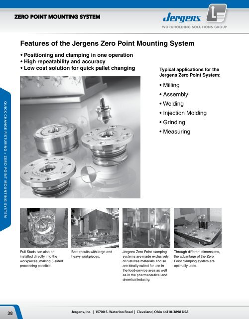
ZERO POINT MOUNTING SYSTEMWORKHOLDING SOLUTIONS GROUP<strong>Jergens</strong>’ <strong>Zero</strong> <strong>Point</strong> <strong>Mounting</strong> <strong>System</strong> –Cut Set-up Times by Up to 90%.Fix, Position and Clamp in a Single Step with<strong>Jergens</strong>’ <strong>Zero</strong> <strong>Point</strong> <strong>Mounting</strong> <strong>System</strong>.QUICK CHANGE FIXTURING » ZERO POINT MOUNTING SYSTEM<strong>Jergens</strong> is proud to introduce <strong>the</strong> best-engineered <strong>Zero</strong> <strong>Point</strong><strong>Mounting</strong> <strong>System</strong> (ZPS) on <strong>the</strong> market. This revolutionarytechnology cuts set-up time by up to 90% by combining fixing,positioning and clamping in a single operation. Available wi<strong>the</strong>i<strong>the</strong>r pneumatic or hydraulic release, <strong>the</strong>se positive lockinglocating modules allow operators to quickly change out largeand small machine fixtures with extreme accuracy and minimaleffort. O<strong>the</strong>r features include:• Repeatability
ZERO POINT MOUNTING SYSTEMWORKHOLDING SOLUTIONS GROUPMechanical Locking <strong>System</strong>Experience high holding force without <strong>the</strong> need to maintainhydraulic pressure.Large Ball DiameterProvides increased strength and even load distribution.No Ball CageFree movement <strong>of</strong> <strong>the</strong> bearing balls reduces friction.Form Fit Ball ChannelTapered contact areas eliminate point loads andreduce failures.Three-<strong>Point</strong> Load DistributionQUICK CHANGE FIXTURING » ZERO POINT MOUNTING SYSTEMEqual load spacing optimizes force distribution.Integrated Safety <strong>System</strong>Process-sure clamping module can always be opened,eliminating <strong>the</strong> need to forcibly remove modules if a failureshould occur.Phone: 877-426-2504 | Fax: +1 216-481-6193 | E-mail: workholding@jergensinc.com | www.jergensinc.com41
ZERO POINT MOUNTING SYSTEMWORKHOLDING SOLUTIONS GROUPClamping and PositioningOn each fixture use:• 1 – <strong>Zero</strong> <strong>Point</strong> Pull Stud• 1 – Timing Pull Stud• The <strong>Zero</strong> <strong>Point</strong> and Timing Studshould be perpendicular• Use any combination <strong>of</strong> clearanceand/or protection Pull StudZERO POINT PULL STUDCLEARANCE PULL STUDFOR HOLD DOWNQUICK CHANGE FIXTURING » ZERO POINT MOUNTING SYSTEMDimensions for machining pull stud mountingsCLEARANCE PULL STUDFOR HOLD DOWNTIMING PULL STUDSize ØD1 ØM S1 S2K5 10 M6 2.5 12K10 15 M8 3.5 16K20 25 M12 5.5 23K40 25 M16 5.5 30Note:• Pull Stud with internal thread for clamping from above• Pull Studs with different diameter D1, preventing interchange <strong>of</strong> <strong>the</strong><strong>Zero</strong> <strong>Point</strong>, timing and clearance Pull Stud during installation.• Pull Stud for series production, (notch type), Floating Pull Stud forcompensation <strong>of</strong> <strong>the</strong>rmal expansion• Automatic lifting <strong>of</strong> <strong>the</strong> pallet / fixtureFigure:Shown with Pull Stud and engagement screw42<strong>Jergens</strong>, <strong>Inc</strong>. | 15700 S. Waterloo Road | Cleveland, Ohio 44110-3898 USA
ZERO POINT MOUNTING SYSTEMWORKHOLDING SOLUTIONS GROUP2-Way Clamping StationHydraulic UnlockingRepeatability < 0.005 mm (0.0002")PartPull-In/Locking ForceNumber Size up to kN / (lbs) A B HA K L L1 ØN R S SM Kg303289 20 2 x 20 / (2 x 4500) 196 396 10 19 45 180 20 G1/4 46 200 21.9303297 40 2 x 40 / (2 x 9000) 296 546 15 26 57 250 25 G1/4 61 320 59.5All linear dimensions in (mm)Note: On request, we can incorporate mounting holes to your requirements in <strong>the</strong> base plate. O<strong>the</strong>r dimensions, gauges and number <strong>of</strong> clamping module layouts on request.4-Way Clamping StationHydraulic UnlockingRepeatability < 0.005 mm (0.0002")QUICK CHANGE FIXTURING » ZERO POINT MOUNTING SYSTEMPart Size Pull-In/Locking ForceNumber up to kN / (lbs) A B HA K L L1 ØN R S SM Kg303321 20 4 x 20 / (4 x 4500) 396 396 10 18 148 180 20 G1/4 46 200 44.0303339 40 4 x 40 / (4 x 9000) 546 546 15 26 217 250 25 G1/4 61 320 110.0All linear dimensions in (mm)Note: On request, we can incorporate mounting holes to your requirements in <strong>the</strong> base plate. O<strong>the</strong>r dimensions, gauges and number <strong>of</strong> clamping module layouts on request.Phone: 877-426-2504 | Fax: +1 216-481-6193 | E-mail: workholding@jergensinc.com | www.jergensinc.com43
ZERO POINT MOUNTING SYSTEMWORKHOLDING SOLUTIONS GROUPPull StudsK5 ModulesHardened Stainless Steel, for hydraulic andpneumatic clamping modules<strong>Zero</strong> <strong>Point</strong> Timing ClearanceProtection Pull StudQUICK CHANGE FIXTURING » ZERO POINT MOUNTING SYSTEMK10 ModulesHardened Stainless Steel,for hydraulic and pneumaticclamping modulesK20 ModulesHardened Stainless Steel,for hydraulic and pneumaticclamping modulesPartNumber Size Description ØDN ØD1 ØD2 H H1 M T g306019 K5 <strong>Zero</strong> <strong>Point</strong> Stud 15.0 10 6 12.7 10.2 — 2.5 15306035 K5 Timing Stud 15.0 10 6 12.7 10.2 — 2.5 15306050 K5 Clearance Stud 14.8 10 6 12.7 10.2 — 2.5 15306076 K5 Protection Plug 14.8 — — 10.2 — M 6 8.0 12PartNumber Size Description ØDN ØD1 ØD2 H H1 M T g303610 K10 <strong>Zero</strong> <strong>Point</strong> Stud 22.0 15 8 19 16 — 3 30303636 K10 Timing Stud 22.0 15 8 19 16 — 3 30304519 K10 Clearance Stud 21.8 15 8 19 16 — 3 30304535 K10 Protection Plug 21.8 — — 16 — M 8 12 30PartNumber Size Description ØDN ØD1 ØD2 H H1 M T g303149 K20 <strong>Zero</strong> <strong>Point</strong> Stud 32.0 25 12 28 23 — 5 110303156 K20 Timing Stud 32.0 25 12 28 23 — 5 110303164 K20 Clearance Stud 31.8 25 12 28 23 — 5 110303172 K20 Protection Plug 31.8 — — 23 — M8 16 110K40 ModulesHardened Stainless Steel,for hydraulic and pneumaticclamping modulesPartNumber Size Description ØDN ØD1 ØD2 H H1 M T g303180 K40 <strong>Zero</strong> <strong>Point</strong> Stud 40.0 25 16 34 29 — 5 180303198 K40 Timing Stud 40.0 25 16 34 29 — 5 180303206 K40 Clearance Stud 39.8 25 16 34 29 — 5 180303214 K40 Protection Plug 39.8 — — 29 — M8 20 18044<strong>Jergens</strong>, <strong>Inc</strong>. | 15700 S. Waterloo Road | Cleveland, Ohio 44110-3898 USA
ZERO POINT MOUNTING SYSTEMWORKHOLDING SOLUTIONS GROUPPull Stud With Internal ThreadHardened for hydraulic and pneumatic clamping modulesPartNumber Size Description ØDN ØD1 ØD2 M S1 U T g427021 K20 <strong>Zero</strong> <strong>Point</strong> Stud 32.0 25 37 M12 5.5 18 5 136427047 K20 Timing Stud 32.0 25 37 M12 5.5 18 5 136427062 K20 Clearance Stud 31.6 25 37 M12 5.5 18 5 136Floating Pull StudHardened for hydraulic and pneumatic clamping modulesPartNumber Size Description ØDN ØD2 H1 g340059 K10 <strong>Zero</strong> <strong>Point</strong> Stud 21.8 12.0 16 25305912 K20 Timing Stud 31.8 15.5 23 80426882 K40 Clearance Stud 39.8 20.0 29 160Note: The floating pull stud is supported by bearings so that it is axially mobile and is usedwhen large distance and angle tolerances between <strong>the</strong> stud holes have to be compensated.The stud has only a holding function and does not take on any lateral load.Engagement Screw For Floating Pull StudStrength class 10.9PartNumber Size Description ØD2 M L L1 L2 L3 g340034 K10 <strong>Zero</strong> <strong>Point</strong> Stud 11.0 M8 35 6 16.1 12.9 24305938 K20 Timing Stud 13.5 M10 50 9 23.1 17.9 55426908 K40 Clearance Stud 17.0 M12 59 10 29.1 19.9 100Horizontal Engagement ScrewsStrength class 10.9For horizontal rapid clamping cylinder on page 48Engagement ScrewsStrength class 10.9For installation and surface mounted clamping modulesQUICK CHANGE FIXTURING » ZERO POINT MOUNTING SYSTEMPartNumber Size M L L1 g303248 K20 M12 56 10.5 100303255 K40 M16 73 13.0 200PartNumber Size M L L1 g306092 K 5 M 6 25 3.4 18303578 K10 M 8 37 6.0 30303222 K20 M12 54 9.0 70303230 K40 M16 69 10.0 130Phone: 877-426-2504 | Fax: +1 216-481-6193 | E-mail: workholding@jergensinc.com | www.jergensinc.com45
ZERO POINT MOUNTING SYSTEMWORKHOLDING SOLUTIONS GROUPThreaded Clamping Modules (K5)Round, Screw-In VersionHydraulic UnlockingCover and piston hardened.Repeatability < 0.005 mm (0.0002")With a small footprint for installation in baseplates, machine tables, clamping pr<strong>of</strong>iles,columns and towers, swivel bridges, machinepallets and clamping pallets.• Installation diagrams on requestQUICK CHANGE FIXTURING » ZERO POINT MOUNTING SYSTEMHardened Stainless SteelPart Size Pull-In/Locking Holding ForceNumber Force up to kN / (lbs) kN / (lbs) ØD ØDN ØD1 H HA ØLK T g480244 K5 5 / (1100) 13 / (2900) M45 x 1 15 39 19.8 5.8 36 14 300All linear dimensions in (mm)Note: Threaded clamping module with a low installation height <strong>of</strong> 19.8 mm and an installation diameter <strong>of</strong> 45 mm (M45 x 1).Hydraulic supply and pressure is only needed for unclamping (min. 50 bar / 725psi, max. 60 bar / 870psi). The threaded clamping module is mechanically lockedin <strong>the</strong> clamped position. The unique mechanical locking system results in virtually no vibration even with extensive machining forces. Fur<strong>the</strong>r more, <strong>the</strong>re are nocumbersome lines or dangers <strong>of</strong> leakage. The contact surface is <strong>the</strong> upper surface <strong>of</strong> <strong>the</strong> housing. The hydraulic design has 1 connection: 1 x unclampingRound, Screw-in VersionPneumatic UnlockingCover and piston hardened.Repeatability < 0.005 mm (0.0002")With a small footprint for installation in baseplates, machine tables, clamping pr<strong>of</strong>iles,columns and towers, swivel bridges, machinepallets and clamping pallets. Pneumaticmodules are optimally suited for use in <strong>the</strong>food, pharmaceutical and chemical industries,as well as in oil-free applications.• Installation diagrams on requestHardened Stainless SteelPart Size Pull-In/Locking Holding ForceNumber Force up to kN / (lbs) kN / (lbs) ØD ØDN ØD1 H HA ØLK T g480343 K5 1.5 / (330) 13 / (2900) M45 x 1 15 39 19.8 5.8 36 14 300All linear dimensions in (mm)Note: Threaded clamping module with a low installation height <strong>of</strong> 19.8 mm and an installation diameter <strong>of</strong> 45 mm (M45 x 1).Pneumatic pressure is needed for unclamping ( min 8 bar/ 116 psi, max 12 bar/ 175 psi). For clamping process pneumatic pressure <strong>of</strong> min 5 bar / 75 psi, max 6bar / 90 psi is required briefly in order to achieve defined pull-in force. The threaded clamping module is mechanically locked in <strong>the</strong> clamped position. The uniquemechanical locking system results in virtually no vibration even with extensive machining forces. Fur<strong>the</strong>r more, <strong>the</strong>re are no cumbersome lines or dangers <strong>of</strong> leakage.The pneumatic design has 2 connections: 1 x unclamping / 1 x clamping.46<strong>Jergens</strong>, <strong>Inc</strong>. | 15700 S. Waterloo Road | Cleveland, Ohio 44110-3898 USA
ZERO POINT MOUNTING SYSTEMWORKHOLDING SOLUTIONS GROUPThreaded Clamping Modules (K10, K20, K40)Round, Hydraulic UnlockingCover and piston hardened.Repeatability < 0.005 mm (0.0002")With a small foot-print for installation in baseplates, machine tables, clamping pr<strong>of</strong>iles,columns and towers, swivel bridges, machinepallets and clamping pallets.• Installation diagrams on requestHardened Stainless SteelPart Pull-in/locking Holding forceNumber Size force up to kN / (lbs) kN / (lbs) Blow out ØD ØDN ØD1 H HA ØLK M T Kg480228 K10 10 / (2250) 25 / (5620) Yes 78 22 50 30 7 60 M5 23 0.45480186 K20 20 / (4500) 55 / (12350) Yes 112 32 78 44 10 88 M6 34 1.40480525 K40 40 / (9000) 105 / (23600) Yes 148 40 102 57 15 118 M8 42 3.40All linear dimensions in (mm)Note: Threaded installation clamping modules have high holding and pull-in forces with very small installation dimensions.Hydraulic supply and pressure is only needed for unclamping (min. 50 bar / 725psi, max. 60 bar / 870psi). The threaded clamping module is mechanically locked in <strong>the</strong>clamped position. The unique mechanical locking system results in virtually no vibration even with extensive machining forces. Fur<strong>the</strong>r more, <strong>the</strong>re are no cumbersomelines or dangers <strong>of</strong> leakage. The contact surface is <strong>the</strong> upper surface <strong>of</strong> <strong>the</strong> housing. The hydraulic design has 1 connection: 1 x unclampingPneumatic UnlockingCover and piston hardened.Repeatability < 0.005 mm (0.0002")With a small footprint for installation in baseplates, machine tables, clamping pr<strong>of</strong>iles,columns and towers, swivel bridges, machinepallets and clamping pallets.• Installation diagrams on requestQUICK CHANGE FIXTURING » ZERO POINT MOUNTING SYSTEMHardened Stainless SteelPart Pull-In/Locking Holding ForceNumber Size force up to kN / (lbs) kN / (lbs) Blow out ØD ØDN ØD1 H HA ØLK M T Kg480202 K10 8 / (1800) 25 / (5620) Yes 78 22 50 30 7 60 M5 23 0.45480160 K20 17 / (3800) 55 / (12350) Yes 112 32 78 44 10 88 M6 34 1.40480541 K40 30 / (6700) 105 / (23600) Yes 148 40 102 57 15 118 M8 42 3.40All linear dimensions in (mm)Note: The installation clamping modules have high holding and pull-in forces with very small installation dimensions.Pneumatic pressure is needed for unclamping ( min 8 bar/ 116 psi, max 12 bar/ 175 psi). For clamping process pneumatic pressure <strong>of</strong> min 5 bar / 75 psi, max 6bar / 90 psi is required briefly in order to achieve defined pull-in force. The installation clamping module is mechanically locked in <strong>the</strong> clamped position. The uniquemechanical locking system results in virtually no vibration even with extensive machining forces. Fur<strong>the</strong>r more, <strong>the</strong>re are no cumbersome lines or dangers <strong>of</strong> leakage.The pneumatic design has 2 connections: 1 x unclamping / 1 x clamping.Phone: 877-426-2504 | Fax: +1 216-481-6193 | E-mail: workholding@jergensinc.com | www.jergensinc.com47
ZERO POINT MOUNTING SYSTEMWORKHOLDING SOLUTIONS GROUPRaised/Mounted Clamping Modules (K5)Round, Hydraulic UnlockingCover and piston hardened.Repeatability < 0.005 mm (0.0002")For mounting on machine tables, clampingpr<strong>of</strong>iles, columns and towers, measuringmachines, assembly stations.• Installation diagrams on requestQUICK CHANGE FIXTURING » ZERO POINT MOUNTING SYSTEMStainless SteelPart Pull-In/Locking Holding ForceNumber Size Force up to kN / (lbs) kN / (lbs) ØB ØD ØDB ØDN HA K R g480566 K5 5 / (1100) 13 / (2900) 5.8 62 54 15 26 15 G1/8 300All linear dimensions in (mm)Note: Hydraulic supply and pressure is only needed for unclamping (min. 50 bar / 725psi, max. 60 bar / 870psi). The installation clamping module is mechanicallylocked in <strong>the</strong> clamped position. The unique mechanical locking system results in virtually no vibration even with extensive machining forces. The contact surface is <strong>the</strong>upper surface <strong>of</strong> <strong>the</strong> housing. The hydraulic design has 1 connection: 1 x unclampingRound, Pneumatic UnlockingCover and piston hardened.Repeatability < 0.005 mm (0.0002")For mounting on machine tables, clampingpr<strong>of</strong>iles, columns and towers, measuringmachines, assembly stations.• Installation diagrams on requestHardened Stainless SteelPart Pull-In/Locking Holding ForceNumber Size Force up to kN / (lbs) kN / (lbs) ØB ØD ØDB ØDN HA K R g480582 K5 1.5 / (330) 13 / (2900) 5.8 62 54 15 26 15 G1/8 300All linear dimensions in (mm)Note: Pneumatic pressure is needed for unclamping ( min 8 bar/ 116 psi, max 12 bar/ 175 psi). For clamping process pneumatic pressure <strong>of</strong> min 5 bar / 75 psi, max 6 bar / 90psi is required briefly in order to achieve defined pull-in force. The installation clamping module is mechanically locked in <strong>the</strong> clamped position. The unique mechanical lockingsystem results in virtually no vibration even with extensive machining forces. The pneumatic design has 2 connections: 1 x unclamping / 1 x clamping.48<strong>Jergens</strong>, <strong>Inc</strong>. | 15700 S. Waterloo Road | Cleveland, Ohio 44110-3898 USA
ZERO POINT MOUNTING SYSTEMWORKHOLDING SOLUTIONS GROUPRaised/Mounted Clamping Modules (K10, K20, K40)Round, Hydraulic UnlockingCover and piston hardened.Repeatability < 0.005 mm (0.0002")For mounting on machine tables, clampingpr<strong>of</strong>iles, columns and towers, measuringmachines,assembly stations in connectionwith clamping bracket on page 50.Hardened Stainless SteelPart Pull-In/Locking Holding ForceNumber Size Force up to kN / (lbs) kN / (lbs) Blow out ØD ØDB ØDN HA K R Kg480608 K10 10 / (2250) 25 / (5620) Yes 78 77.5 22 30 16.50 G1/8 0.90480624 K20 20 / (4500) 55 / (12350) Yes 112 110.0 32 50 28.25 G1/4 2.70480640 K40 40 / (9000) 105 / (23600) Yes 148 146.0 40 62 32.50 G1/4 3.80All linear dimensions in (mm)Note: Hydraulic supply and pressure is only needed for unclamping (min. 50 bar / 725psi, max. 60 bar / 870psi). The installation clamping module is mechanicallylocked in <strong>the</strong> clamped position. The unique mechanical locking system results in virtually no vibration even with extensive machining forces. Fur<strong>the</strong>r more, <strong>the</strong>reare no cumbersome lines and no danger <strong>of</strong> leakage. The contact surface is <strong>the</strong> upper surface <strong>of</strong> <strong>the</strong> housing. The hydraulic design has 1 connection: 1 x unclampingRound, Pneumatic UnlockingCover and piston hardened.Repeatability < 0.005 mm (0.0002")For mounting on machine tables,clamping pr<strong>of</strong>iles, columns and towers,measuring machines,assembly stationsin connection with clamping bracketon page 50.QUICK CHANGE FIXTURING » ZERO POINT MOUNTING SYSTEMHardened Stainless SteelPart Pull-In/Locking Holding ForceNumber Size Force up to kN / (lbs) kN / (lbs) Blow out ØD ØDB ØDN HA K R Kg480665 K10 8 / (1800) 25 / (5620) Yes 78 77.5 22 30 16.50 G1/8 0.90480681 K20 17 / (3800) 55 / (12350) Yes 112 110.0 32 50 28.25 G1/4 2.60480707 K40 30 / (6700) 105 / (23600) Yes 148 146.0 40 62 32.50 G1/4 6.40All linear dimensions in (mm)Note: Pneumatic pressure is needed for unclamping ( min 8 bar/ 116 psi, max 12 bar/ 175 psi). For clamping process pneumatic pressure <strong>of</strong> min 5 bar / 75 psi, max 6 bar /90 psi is required briefly in order to achieve defined pull-in force. The installation clamping module is mechanically locked in <strong>the</strong> clamped position. The unique mechanical lockingsystem results in virtually no vibration even with extensive machining forces. The pneumatic design has 2 connections: 1 x unclamping / 1 x clamping.Phone: 877-426-2504 | Fax: +1 216-481-6193 | E-mail: workholding@jergensinc.com | www.jergensinc.com49
ZERO POINT MOUNTING SYSTEMWORKHOLDING SOLUTIONS GROUPClamping Bracket for Raised/Mounted Clamping ModulesBlack NitridedClamping flanges are used to fastenraised/mounted clamping modules on<strong>the</strong> machine table. See page 49.• Special clamping flanges for variousT-slot tables• Clamping flange and housingmanufactured as a single pieceQUICK CHANGE FIXTURING » ZERO POINT MOUNTING SYSTEMStainless SteelPartPiecesNumber Size Per Module ØD ØDB H ØLK M g303495 10 2 114 77.5 7.75 94 8.5 180302901 20 2 164 110.0 13.00 136 11.0 400302919 40 2 202 146.0 16.00 172 13.0 550All linear dimensions in (mm)Flange Type Installation Modules<strong>Features</strong>:• Oil supply by pipes or manifolds• Integrated centering• Provided as assembled unitBenefits:• Simple design and manufacturing <strong>of</strong> adaptor plate• Weight saving due to less thickness for adaptor plate• Easy to adapt to existing mounting angles and cubesInstallation comparisonStandard Clamping ModuleCover RingFlange Type ModuleOilOilInstallation ModuleFlangeOil Supply by PipesOil Supply by ManifoldBase PlateNo seal face neededcentering onlySealing faceO-ring50<strong>Jergens</strong>, <strong>Inc</strong>. | 15700 S. Waterloo Road | Cleveland, Ohio 44110-3898 USA
ZERO POINT MOUNTING SYSTEMWORKHOLDING SOLUTIONS GROUPFlange Type Installation ModulesHydraulic ReleaseCover and piston hardened.Repeatability < 0.005 mm (0.0002")Hardened Stainless SteelPart Pull-In/Locking Holding ForceNumber Size force up to kN / (lbs) kN / (lbs) Blow out ØDA ØDN ØD1 HA K ØLK M R T Kg480301 K10 10 / (2250) 25 / (5620) Yes 100 22 67 24 9 90 M5 G1/8 5.9 1.35480269 K20 20 / (4500) 55 / (12350) Yes 136 32 100 35 13 124 M6 G1/8 8.9 3.76480723 K40 40 / (9000) 105 / (23600) Yes 180 40 120 45 15 163 M8 G1/8 11.9 4.97All linear dimensions in (mm)Note: Combines features <strong>of</strong> <strong>the</strong> Threaded Module and Raised/Mounted module. Especially designed when installation space is limited and base plate or angle plate hasrelatively thin dimensions. The positioning <strong>of</strong> <strong>the</strong> module is simple and accurate when using <strong>the</strong> precision flange diameter. Hydraulic supply is possible by manifolds orpipes/hoses. Hydraulic supply and pressure is only needed for unclamping (min. 50 bar / 725psi, max. 60 bar / 870psi). The module is mechanically locked in <strong>the</strong> clampedposition. The unique mechanical locking system results in virtually no vibration even with extensive machining forces. The hydraulic design has 1 connection: 1 x unclampingPneumatic ReleaseCover and piston hardened.Repeatability < 0.005 mm (0.0002")QUICK CHANGE FIXTURING » ZERO POINT MOUNTING SYSTEMHardened Stainless SteelPart Pull-In/Locking Holding ForceNumber Size force up to kN / (lbs) kN / (lbs) Blow out ØDA ØDN ØD1 HA K ØLK M R T Kg480327 K10 8 / (1800) 25 / (5620) — 100 22 67 24 9 90 M5 G1/8 5.9 1.35480285 K20 17 / (3800) 55 / (12350) — 136 32 100 35 13 124 M6 G1/8 8.9 4.97480749 K40 30 / (6700) 105 / (23600) — 180 40 120 45 15 163 M6 G1/8 11.9 4.97All linear dimensions in (mm)Note: Combines features <strong>of</strong> <strong>the</strong> Threaded Module and Raised/Mounted module. Especially designed when installation space is limited and base plate or angle plate hasrelatively thin dimensions. The positioning <strong>of</strong> <strong>the</strong> module is simple and accurate when using <strong>the</strong> precision flange diameter. Pneumatic supply is possible by manifolds orpipes/hoses. Pneumatic pressure is needed for unclamping ( min 8 bar/ 116 psi, max 12 bar/ 175 psi). For clamping process pneumatic pressure <strong>of</strong> min 5 bar / 75 psi, max6 bar / 90 psi is required briefly in order to achieve defined pull-in force. The installation clamping module is mechanically locked in <strong>the</strong> clamped position. The unique mechanicallocking system results in virtually no vibration even with extensive machining forces. The pneumatic design has 2 connections: 1 x unclamping / 1 x clamping.Phone: 877-426-2504 | Fax: +1 216-481-6193 | E-mail: workholding@jergensinc.com | www.jergensinc.com51
ZERO POINT MOUNTING SYSTEMWORKHOLDING SOLUTIONS GROUPHorizontal Rapid-Clamping CylinderHydraulic UnlockingCover and piston hardened.Repeatability < 0.005 mm (0.0002")QUICK CHANGE FIXTURING » ZERO POINT MOUNTING SYSTEMHardened Stainless Steel• For easy handling <strong>of</strong> heavy fixtures• Makes palletization very quick by hookinginto a hole at <strong>the</strong> top and moving downwards• No searching for <strong>the</strong> holes• No damage to <strong>Zero</strong> <strong>Point</strong> bore or pull studsPart Pull-In/Locking Holding Advance Motion, Hydr.Number Size Force up to kN / (lbs) Force kN / (lbs) Blow Out Suspension Piston Kg303065 K20 20 / (4500) 55 / (12350) — — 2.1306217 K20 20 / (4500) 55 / (12350) — Yes 2.1303073 K20 20 / (4500) 55 / (12350) Yes — 2.1306233 K20 20 / (4500) 55 / (12350) Yes Yes 2.1303107 K40 40 / (9000) 105 / (23600) — — 5.2306258 K40 40 / (9000) 105 / (23600) — Yes 5.2303115 K40 40 / (9000) 105 / (23600) Yes — 5.2306274 K40 40 / (9000) 105 / (23600) Yes Yes 5.2Dimensions (mm)Part Number ØD ØDN ØD1 ØD2 H HA ØLK ØLK1 M M1 T T1303065 112 32 78 40 109 10 88 60 M6 M6 56.5 99306217 112 32 78 40 109 10 88 60 M6 M6 56.5 99303073 112 32 78 40 109 10 88 60 M6 M6 56.5 99306233 112 32 78 40 109 10 88 60 M6 M6 56.5 99303107 148 40 102 48 144 15 118 76 M8 M6 73 129306258 148 40 102 48 144 15 118 76 M8 M6 73 129303115 148 40 102 48 144 15 118 76 M8 M6 73 129306274 148 40 102 48 144 15 118 76 M8 M6 73 129All linear dimensions in (mm)Note: As standard, <strong>the</strong>re is a manaul or hydraulic advance motion <strong>of</strong> <strong>the</strong> suspension piston.Release ModeClamped Mode52<strong>Jergens</strong>, <strong>Inc</strong>. | 15700 S. Waterloo Road | Cleveland, Ohio 44110-3898 USA