Features of the Jergens Zero Point Mounting System - Jergens Inc.
Features of the Jergens Zero Point Mounting System - Jergens Inc.
Features of the Jergens Zero Point Mounting System - Jergens Inc.
- No tags were found...

You also want an ePaper? Increase the reach of your titles
YUMPU automatically turns print PDFs into web optimized ePapers that Google loves.
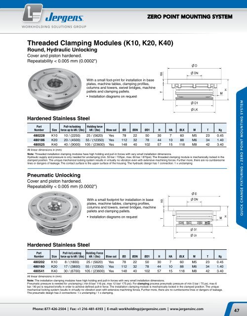
ZERO POINT MOUNTING SYSTEMWORKHOLDING SOLUTIONS GROUPThreaded Clamping Modules (K10, K20, K40)Round, Hydraulic UnlockingCover and piston hardened.Repeatability < 0.005 mm (0.0002")With a small foot-print for installation in baseplates, machine tables, clamping pr<strong>of</strong>iles,columns and towers, swivel bridges, machinepallets and clamping pallets.• Installation diagrams on requestHardened Stainless SteelPart Pull-in/locking Holding forceNumber Size force up to kN / (lbs) kN / (lbs) Blow out ØD ØDN ØD1 H HA ØLK M T Kg480228 K10 10 / (2250) 25 / (5620) Yes 78 22 50 30 7 60 M5 23 0.45480186 K20 20 / (4500) 55 / (12350) Yes 112 32 78 44 10 88 M6 34 1.40480525 K40 40 / (9000) 105 / (23600) Yes 148 40 102 57 15 118 M8 42 3.40All linear dimensions in (mm)Note: Threaded installation clamping modules have high holding and pull-in forces with very small installation dimensions.Hydraulic supply and pressure is only needed for unclamping (min. 50 bar / 725psi, max. 60 bar / 870psi). The threaded clamping module is mechanically locked in <strong>the</strong>clamped position. The unique mechanical locking system results in virtually no vibration even with extensive machining forces. Fur<strong>the</strong>r more, <strong>the</strong>re are no cumbersomelines or dangers <strong>of</strong> leakage. The contact surface is <strong>the</strong> upper surface <strong>of</strong> <strong>the</strong> housing. The hydraulic design has 1 connection: 1 x unclampingPneumatic UnlockingCover and piston hardened.Repeatability < 0.005 mm (0.0002")With a small footprint for installation in baseplates, machine tables, clamping pr<strong>of</strong>iles,columns and towers, swivel bridges, machinepallets and clamping pallets.• Installation diagrams on requestQUICK CHANGE FIXTURING » ZERO POINT MOUNTING SYSTEMHardened Stainless SteelPart Pull-In/Locking Holding ForceNumber Size force up to kN / (lbs) kN / (lbs) Blow out ØD ØDN ØD1 H HA ØLK M T Kg480202 K10 8 / (1800) 25 / (5620) Yes 78 22 50 30 7 60 M5 23 0.45480160 K20 17 / (3800) 55 / (12350) Yes 112 32 78 44 10 88 M6 34 1.40480541 K40 30 / (6700) 105 / (23600) Yes 148 40 102 57 15 118 M8 42 3.40All linear dimensions in (mm)Note: The installation clamping modules have high holding and pull-in forces with very small installation dimensions.Pneumatic pressure is needed for unclamping ( min 8 bar/ 116 psi, max 12 bar/ 175 psi). For clamping process pneumatic pressure <strong>of</strong> min 5 bar / 75 psi, max 6bar / 90 psi is required briefly in order to achieve defined pull-in force. The installation clamping module is mechanically locked in <strong>the</strong> clamped position. The uniquemechanical locking system results in virtually no vibration even with extensive machining forces. Fur<strong>the</strong>r more, <strong>the</strong>re are no cumbersome lines or dangers <strong>of</strong> leakage.The pneumatic design has 2 connections: 1 x unclamping / 1 x clamping.Phone: 877-426-2504 | Fax: +1 216-481-6193 | E-mail: workholding@jergensinc.com | www.jergensinc.com47