BALL LOCK ® MOUNTING SYSTEM QUICK CHANGE ... - Jergens Inc.
BALL LOCK ® MOUNTING SYSTEM QUICK CHANGE ... - Jergens Inc.
BALL LOCK ® MOUNTING SYSTEM QUICK CHANGE ... - Jergens Inc.

Create successful ePaper yourself
Turn your PDF publications into a flip-book with our unique Google optimized e-Paper software.
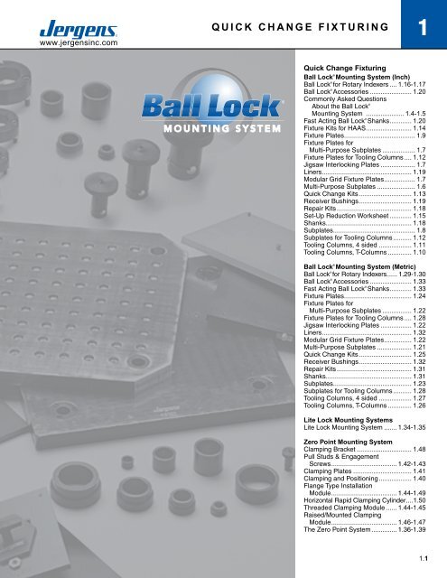
www.jergensinc.com<strong>BALL</strong> <strong>QUICK</strong> <strong>LOCK</strong> ®<strong>CHANGE</strong> <strong>MOUNTING</strong> FIXTURING <strong>SYSTEM</strong>1Quick Change FixturingBall Lock ® Mounting System (<strong>Inc</strong>h)Ball Lock ® for Rotary Indexers..... 1.16-1.17Ball Lock ® Accessories........................ 1.20Commonly Asked QuestionsAbout the Ball Lock ®Mounting System ...................... 1.4-1.5Fast Acting Ball Lock ® Shanks............. 1.20Fixture Kits for HAAS.......................... 1.14Fixture Plates........................................ 1.9Fixture Plates forMulti-Purpose Subplates................... 1.7Fixture Plates for Tooling Columns..... 1.12Jigsaw Interlocking Plates.................... 1.7Liners.................................................. 1.19Modular Grid Fixture Plates.................. 1.7Multi-Purpose Subplates...................... 1.6Quick Change Kits.............................. 1.13Receiver Bushings.............................. 1.19Repair Kits.......................................... 1.18Set-Up Reduction Worksheet............. 1.15Shanks................................................ 1.18Subplates.............................................. 1.8Subplates for Tooling Columns........... 1.12Tooling Columns, 4 sided................... 1.11Tooling Columns, T-Columns.............. 1.10Ball Lock ® Mounting System (Metric)Ball Lock ® for Rotary Indexers...... 1.29-1.30Ball Lock ® Accessories........................ 1.33Fast Acting Ball Lock ® Shanks............. 1.33Fixture Plates...................................... 1.24Fixture Plates forMulti-Purpose Subplates................. 1.22Fixture Plates for Tooling Columns..... 1.28Jigsaw Interlocking Plates.................. 1.22Liners.................................................. 1.32Modular Grid Fixture Plates................ 1.22Multi-Purpose Subplates.................... 1.21Quick Change Kits.............................. 1.25Receiver Bushings.............................. 1.32Repair Kits.......................................... 1.31Shanks................................................ 1.31Subplates............................................ 1.23Subplates for Tooling Columns........... 1.28Tooling Columns, 4 sided................... 1.27Tooling Columns, T-Columns.............. 1.26Lite Lock Mounting SystemsLite Lock Mounting System........ 1.34-1.35Zero Point Mounting SystemClamping Bracket............................... 1.48Pull Studs & EngagementScrews..................................... 1.42-1.43Clamping Plates................................. 1.41Clamping and Positioning................... 1.40Flange Type InstallationModule..................................... 1.44-1.49Horizontal Rapid Clamping Cylinder.....1.50Threaded Clamping Module....... 1.44-1.45Raised/Mounted ClampingModule..................................... 1.46-1.47The Zero Point System............... 1.36-1.39Phone 800-537-4367 or +1 216-486-5540 • Fax: +1 216-481-6193 • E-mail: info@jergensinc.com • www.jergensinc.com 1.1
1 <strong>BALL</strong> <strong>LOCK</strong> ® <strong>MOUNTING</strong> <strong>SYSTEM</strong>www.jergensinc.comWe Put It All Together… In Seconds.Maximize productivity levels anddramatically increase throughput withBall Lock ® .Looking to realize the full benefits of lean manufacturing? Thenyou need the one system that puts it all together, so you can putit all together…and that’s Ball Lock ® .Ball Lock ® is the industry’s most popular quick-change, fixturingflexiblemounting system that can be configured to create leanoptimizedsolutions for your most demanding needs.The Ball Lock ® Mounting System is used as aQuick Change Solution on the following:• CNC Machines• Palletized Fixtures• Stamping• Fabricating• Injection Molding• Packaging Machines• Assembly Machines• EDM• Robotics• Welding Fixtures1.2<strong>Jergens</strong>, <strong>Inc</strong>. • <strong>Jergens</strong> Way • 15700 S. Waterloo Road • Cleveland, Ohio 44110-3898 USA
www.jergensinc.com<strong>BALL</strong> <strong>LOCK</strong> ®<strong>MOUNTING</strong> <strong>SYSTEM</strong>1Lean Manufacturing and Set Up Reduction ApplicationsAccurately Locate and Lock Fixture Plates to Subplates in Seconds…With No Indicating Required.Machining Cast PartPrevious Set Up Method:Located part with dowel pins, bolted part to tombstonefixture. Indicated part to zero datum point.Set Up Using Ball Lock ® System:Mount parts to fixture plate while machining otherparts. Mount fixture plate to tombstone using BallLock ® shanks. No indicating required becausesystem provides + 0.0005 (±0.013mm)repeatability.Previous Set-Up Time:15 minutesSet Up Time With Ball Lock ® System:60 secondsCNC Machine Base:Drilling and reaming forged part.Previous Set Up Method:Fixture plate located with dowel pins bolted tomachine base. Fixture plate and parts indicated.Set Up Using Ball Lock ® System:Parts are pre-mounted on fixture plate, which isthen mounted to machine base using Ball Lock ®shanks. No need to indicate.Previous Set Up Time:7 minutesSet Up Time with Ball Lock ® System:60 secondsCNC Vertical Machining CenterMachining aircraft valve partsPrevious Set Up Method:New Project. NewMachine.No Prior History.Set Up Using Ball Lock ® System:Using BallLock ® Jig Saw Plate on Multi-Purpose Subplateenables operator to mount two more vises onthe fixture. No indicating needed.Previous Set Up Time:New Set Up.Set Up Time With Ball Lock ® System:80 seconds setting up six vises.Two-Sided TombstoneDrilling and tapping cylindrical bodies.Previous Set Up Method:Fixture located and bolted to tombstone. Had tobe indicated.Set Up Using Ball Lock ® System:Fixture plate mounted and located with Ball Lock ®shanks. No need to indicate.Previous Set Up Time:12 minutesSet Up Time with Ball Lock ® System:45 secondsPhone 800-537-4367 or +1 216-486-5540 • Fax: +1 216-481-6193 • E-mail: info@jergensinc.com • www.jergensinc.com 1.3
1 <strong>BALL</strong> <strong>LOCK</strong> ® <strong>MOUNTING</strong> <strong>SYSTEM</strong>www.jergensinc.comLocatesThe Ball Lock ® System accurately positionsyour fixtureplate with a repeatability of±0.0005" (±0.013mm) or better, minimizingthe need to indicate your fixture.LocksThe Ball Lock ® System securely holds fixtureplates to subplates with up to 20,000 lbs.(9000 kg) of hold-down force per shank.The Ball Lock ® Mounting System is designedto speed the accurate locating and lockingof fixture plates to subplates. The systemconsists of three parts: a Locating Shank,a Liner Bushing, and a Receiver Bushing.Using the Ball Lock ® Mounting System isa simple process: Install a subplate withreceiver bushings on your machine table;add your fixture plate with two locating linerbushings; then insert two locating shanksthrough the liners and into the receiverbushings to provide accurate location.2 1 / 2 turns of the set screw in each of thelocating shanks provides positive holdingforce. Additional Ball Lock ® Shanks areinserted through clearance holes in thefixture plate and set screws tightened foradditional holding force distributed acrossthe fixture plate.It is recommended that the use ofthe Ball Lock ® Mounting System forlocating and clamping of fixture platesbe incorporated in a systematicprocess. All fixture plates shouldhave two locating points positionedas far apart as possible. There is noadvantage to having more than twoThe Ball Lock ® Mounting Systemprovides a method of quickly andaccurately locating fixtures ontomachine tables. The Ball Lock ®Mounting System has done formachining centers what the JapaneseSMED concept did for presses.Instead of single minute exchange ofdies, Ball Lock ® provides single minuteexchange of fixtures. Fixtures canoften be exchanged in less than aminute and with position repeatabilityof ±0.0005” (±0.013mm). Fixturescan be exchanged between differentmachines when both are using the<strong>Jergens</strong> Ball Lock ® Mounting System.Commonly Asked QuestionsQ. What is the Ball Lock ®Mounting System?A. It is a means of locating and lockingtwo flat surfaces together, normally afixture plate and a sub-plate.Q. How does it locate?A. Similar to locating pins, two BallLock ® shanks (pins) pass through twoprecision liner bushings on the fixtureplate and into two precision receiverbushings on the subplate.Q. How does it lock?A. Inside the shank are three balls thatexpand into a tapered groove in thereceiver bushing. This action drawsthe plates together. The locking ballsare activated by turning a setscrew inthe head of the shank, which pushesa 4th ball to distribute the clampingforces between the 3 locking balls.Q. How many shanks are requiredto locate and lock each fixture?A. Only two shanks, passing throughbushings in the fixture plates, arerequired for location. However,additional shanks passing throughclearance holes in the fixture platewill provide additional holding forcedistributed across the plate.1.4<strong>Jergens</strong>, <strong>Inc</strong>. • <strong>Jergens</strong> Way • 15700 S. Waterloo Road • Cleveland, Ohio 44110-3898 USA
www.jergensinc.com<strong>BALL</strong> <strong>LOCK</strong> ®<strong>MOUNTING</strong> <strong>SYSTEM</strong>1Ball Lock ®ShankLiner BushingBall Lock ®ShankLiner BushingFixture PlateFixture PlateSlip Fit HoleSocket Head CapScrews (3)Press Fit HoleMachineTable orSubplateFace MountBushingDrilled HoleSubplateCounter-BoredHoleBack Mount BushingMounting Method WithFace Mount BushingMounting Method WithBack Mount Bushinglocating points. If more than two flangedshanks are required to provide additionalhold- down force, omit liner bushings inthe additional holes in the fixture plate andallow 0.030" (0.76mm) over the nominalsize. The additional clearance will insurethat these holes have no influence on thelocating holes.How accurate should positioning be?The center distance of the receiver bushingsin the machine table, tombstone, or subplateshould be as accurate as possible ±0.0002"(±0.005mm) recommended. Accuratelocation will assure interchangeability ofnumerous fixture plates. For accuraterepeatability within ±0.0005" (±0.013mm)of true position, both liner bushings in thefixture plate should be primary liners andthe center distance tolerance should be±0.0002" (±0.005mm). For a slightly looserfit, repeatability within 0.0015" (0.04mm)of true position, use one primary and onesecondary liner with a center distancetolerance of ±0.001" (±0.003mm).Q. Is there a preferable location forthe liner bushing?A. System repeatability is improvedif the liners are located at oppositecorners of a rectangular fixture plate.For consistency, we recommendlocating the liner bushings at top leftand bottom right.Q. What are the advantages of usingthe Ball Lock ® System over theconventional method of dowelpins and cap screws?A. Both locating and locking areaccomplished in the same motion. BallLock ® shanks require only 2.5 turnsto lock a 1/2–13 (M12) screw with ¾"(18mm) of thread engagement require10 turns to lock. On CNC machines,the repeatability of fixture locationsmakes indicating of the fixtureunnecessary.Q. How do I recess the fixtureplatefor a clear surface ?A. Counterbore the fixture plate to adiameter large enough to allow easyremoval of the shank.Note: The thickness of the plate sectionunder the head of the shank is critical andmust conform to mounting instructions .Q. What if my plate is thinner thanthe recommended thickness?A. By adjusting the depth of thecounterbore for the receiver bushingin the subplate, you can still use theBall Lock ® System. If there are anyquestions on this type of application,please call 1-800-JERGENS.Q. Can I use the shanks in a heatedenvironment?A. The shank is made of alloy steel,heat treated to 40-45Rc and shouldwith stand temperatures up to 400°F.(200°C).Note: Thermal expansion of fixture platesmay affect the center distance toleranceand repeatability.Phone 800-537-4367 or +1 216-486-5540 • Fax: +1 216-481-6193 • E-mail: info@jergensinc.com • www.jergensinc.com 1.5
1 <strong>BALL</strong> <strong>LOCK</strong> ® <strong>MOUNTING</strong> <strong>SYSTEM</strong>INCH DIMENSIONSwww.jergensinc.comINCH PRE-MACHINED FIXTURE/SUBPLATESMulti-Purpose Subplates40x20 Multi-Purpose SubplatePart Number Wt. (lbs)49112 285The <strong>Jergens</strong> Multi-Purpose Subplate accommodatesa wide variety of fixture plates and vises. Thisversatility facilitates using the same VMC fordiverse products in repetitive runs, long and shortbatch sizes.• FreMax 15 Steel or Equivalent• Thickness: 1 1/4” ±0.005"• Parallel within 0.001"2870628801494062871928713 or 28715287274911217.000012.000017.000012.0000(18) 20MM FACE MOUNTBUSHINGSINSTALLED5/8" BORED HOLEFOR SINEFIXTURE KEYS(2) PLACES6.000012.00002017.0000(8) 25MM FACE MOUNTBUSHINGSINSTALLED8.00008.00008.00008.000040Fixture Plate Options for Multi-Purpose Subplates – Aluminum or SteelNumber of Fixture Receiver Required NumberPlates/Vises That Mount Bushing Receiver Ball Lock ® of ShanksFixture Plate*/Vise Thickness of on Multi-Purpose Center Bushing Shank Required PerPart Number Fixture Plate Subplate Distance Size Part Number Fixture Plate/Vise28713 (14 x 14)Fixture Plate28715 (16 x 16)Fixture Plate28801 (16 x 16)Modular Grid Plate28706 JigsawInterlocking Plate28727 (20 x 20)Fixture Plate28719 (20 x 16)Fixture Plate494066" Jigsaw Base Vise3/4” 2 12 x 12 20 mm 49601 43/4” 2 12 x 12 20 mm 49601 41 1/8”** 2 12 x 12 20 mm 49602 43/4” 4 8 x 12 20 mm 49601 31” 2 17 x 17 25 mm 49612 43/4" 1 16 x 12 20 mm 49601 43/4" 4 8 x 12 20 mm 49601 3* See next page for dimensional data on fixture plates. Part numbers shown for aluminum plates, also available in steel.** Counterbored to 1" at mounting holes.1.6<strong>Jergens</strong>, <strong>Inc</strong>. • <strong>Jergens</strong> Way • 15700 S. Waterloo Road • Cleveland, Ohio 44110-3898 USA
www.jergensinc.com<strong>BALL</strong> <strong>LOCK</strong> ®<strong>MOUNTING</strong> <strong>SYSTEM</strong>INCH DIMENSIONS1Fixture Plates for Multi-Purpose Subplate14x14x3/4" Fixture PlateAluminum PlatePart Number Wt. (lbs)28713 1416x16x3/4" Fixture PlateAluminum PlatePart Number Wt. (lbs)28715 18Steel PlatePart Number Wt. (lbs)28813 42Steel PlatePart Number Wt. (lbs)28815 55• Cast Aluminum or FreMax 15 Steel or equivalent• Thickness: 3/4" ±0.005"• Parallel within 0.001" Steel• Mounts to subplates with Ball Lock ® Shank 49601 (20 X 3/4")16x16 Modular Grid Fixture PlateSteel PlatePart Number Wt. (lbs)28801 80(2) 20MMPRIMARY LINERS• FreMaxINSTALLED (2) PLACES15 Steel or equivalent• Thickness: 1 1/8” ±0.005"• Parallel within 0.001"• Mounts to subplates with Ball Lock ®Shank 49602 (20 x 1")(2) 20MMPRIMARY LINERSINSTALLEDCLEARANCE HOLESFOR HOLDDOWNCLEARANCE12.0000HOLESFOR HOLDDOWN(2) PLACES 16.0000-0.000.625 +0.0005 x .25 DeepCOUNTERBORE1/2-13TAPPED HOLE-0.000.625 +0.0005 x .25 DeepCOUNTERBOREINCH PRE-MACHINED FIXTURE/SUBPLATES12.000012.0000Clearance holes forholddown (2)places5/8” Bored hole forsine fixture keys(2) places12.000016.00001.50TYP12.000016.00001/2-13TAPPED HOLE6.000(2) 20mm PrimaryLiners Installed12.000016.00001.50TYPJigsaw Interlocking Fixture PlateAluminum Steel Plate <strong>Jergens</strong> VisePlate Part No Wt. Part No Wt. A B C D P/N28705 6 - - 7.97 5.97 15.00 6.0000 4940128706 11 28806 34 9.97 7.97 16.00 8.0000 49402• Cast Aluminum or FreMax 15 Steel or equivalent• Thickness: 3/4” ±0.005"• Parallel within 0.001" Steel• For use with narrow base 4" or 6" vise models• Design allows close vise spacing for more parts per run• Easily mounts to Subplates using theBall Lock ® Shank 49601 (20 x 3/4")• Useful for high density fixturing of small parts20x20x1" Fixture PlateAluminum PlatePart Number Wt. (lbs)28727 38• Cast Aluminum or FreMax 15 Steel or equivalent• Thickness: 1” ±0.005"• Parallel within 0.001" Steel• Mounts to subplates with Ball Lock ® Shank 49612 (25 X 1")17.0000Steel PlatePart Number Wt. (lbs)28827 114ClearanceClearanceholehole forfor holddown17.0000Clearance holes forholddown (2) places5/8” Bored holefor sine fixture key(2) placesAB(2) 20mm PrimaryLiners Installed12.00006.0000D8.500(2) 25mm PrimaryLiners InstalledCPhone 800-537-4367 or +1 216-486-5540 • Fax: +1 216-481-6193 • E-mail: info@jergensinc.com • www.jergensinc.com 1.7
1 <strong>BALL</strong> <strong>LOCK</strong> ® <strong>MOUNTING</strong> <strong>SYSTEM</strong>INCH DIMENSIONSwww.jergensinc.comBall Lock ® Standard SubplatesINCH PRE-MACHINED FIXTURE/SUBPLATES12.00006.000• ••• ••12.00005/8 Bored holes forsine fixture keys(2) places(2) 20mm face mountbushings installed• ••• ••16x16 SubplatePart Number Wt (lbs)49101 81Equipped with four 20mm receiver bushings for usewith 14x14 or 16x16 fixture plates. Ideal for horizontalmachining centers or multiple pallet machining centers.• Fremax 15 steel plate or equivalent• Thickness: 1-1/8" ±0.005"• Parallel within 0.001"1.6009.0000 12.525x16 Dual Station Subplate• ••• ••• ••• ••• ••• ••Part Number Wt (lbs)49111 12812.000011.00028713 or 28715166.0005/8 Bored holes forsine fixture keys(2) places(12) 20mm face mountbushings installed287112.0• ••• ••• ••• ••• ••• ••491116.00012.0000Aluminum Steel Plate Number PlatePlate Part Part of Fixture Width andNumber Number Plates Length28713 28813 1 14"x14"28715 28815 1 16"x16"28711 28811 2 12"x14"25Equipped with twelve installed 20mm receiver bushings toeasily locate and mount <strong>Jergens</strong> Standard Fixture Plates:• Fremax 15 steel plate or equivalent• Thickness: 1-1/8" ±0.005"• Parallel within 0.001"3/4˚˚˚˚5/8 Bored holes forsine fixture keys(2) places(4)1/2 dia. formounting to table(2) 16mm face mountbushings installed12.000015˚˚˚2.508.0000 102.50˚15x10 Bridgeport - Style SubplatePart Number Wt (lbs)49121 32Equipped with four installed 16mm receiver bushingsand 1/2" mounting holes. Used with the Bridgeport stylefixture plates 28731 or 28831.• Thickness: 3/4" ±0.005"• Parallel within 0.001"Ball Lock ® Quick Change Kits include all components needed in a single package. See page 1.13 for details.1.8<strong>Jergens</strong>, <strong>Inc</strong>. • <strong>Jergens</strong> Way • 15700 S. Waterloo Road • Cleveland, Ohio 44110-3898 USA
www.jergensinc.com<strong>BALL</strong> <strong>LOCK</strong> ®<strong>MOUNTING</strong> <strong>SYSTEM</strong>INCH DIMENSIONS1Ball Lock ® Fixture Plates• Cast Aluminum or FreeMax 15 Steel or equivalent• Thickness tolerance ±0.005"• Parallel within 0.001" Steel• 6061–T-651 Aluminum plates, within .001 available upon requestAluminum Ball Lock ® Fixture Plates with 2 Primary Liners InstalledPlate PartPlate PartNumber Weight Number WeightAluminum (lbs) Steel (lbs)PlateDimensions(in.)PlateThickness(in.)±.005Shank SizeDia. (mm)Ball Lock ®ShankPartNumber28706 9 28806 34 9.97 x 16 3/4 20 4960128711 12 28811 36 12 x14 3/4 20 4960128713 14 28813 42 14 x14 3/4 20 4960128715 18 28815 55 16 x 16 3/4 20 4960128722 16 28822 48 12 x 14 1 25 4961228724 19 28824 56 14 x 14 1 25 4961228726 24 28826 73 16 x 16 1 25 4961228719 23 28819 68 20 x 16 3/4 20 4960128727 38 28827 114 20 x 20 1 25 4961228731 11 28831 32 15 x 10 3/4 16 49608– – 28801 80 16 x 16 1 1/8 20 49602• Machined to close tolerances• Repeatability ±0.0005" or better• Reduces fixture set-up andassembly time• Provided with 5/8" bored holes forsine fixture keys• For horizontal or vertical machiningcenters, Tool Room Mills, ormultiple pallet machining centersINCH PRE-MACHINED FIXTURE/SUBPLATESCustom Sizes Available<strong>Jergens</strong> will make Ball Lock ® fixture plate or subplates to yourspecifications. Call 1-800-JERGENS for further information.15x10x3/4" Fixture Plate Bridgeport Style12x14x3/4" Fixture PlateAluminum PlatePart Number Wt. (lbs)28731 11Steel PlatePart Number Wt. (lbs)28831 32Aluminum PlatePart Number Wt. (lbs)28711 12Steel PlatePart Number Wt. (lbs)28811 369.00004.000Clearance Hole forHolddown (2) Places5/8 Bored Holes forSine Fixture Keys(2) Places(2) 16mm PrimaryLiners Installed8.000012.0000Clearance Hole forHolddown (2) Places5/8 Bored holes forsine fixture keys(2) places12.00006.000(2) 20mm PrimaryLiners InstalledPhone 800-537-4367 or +1 216-486-5540 • Fax: +1 216-481-6193 • E-mail: info@jergensinc.com • www.jergensinc.com 1.9
1 <strong>BALL</strong> <strong>LOCK</strong> ® <strong>MOUNTING</strong> <strong>SYSTEM</strong>INCH DIMENSIONSwww.jergensinc.comBall Lock ® T-ColumnsFixturePlateINCH PRE-MACHINED FIXTURE/SUBPLATES• Class 40 Cast Iron• Also available in Aluminum• Ball Lock ® Receiver Bushings and Liner Bushings installed• Perpendicularity is 0.001" per footCustom Sizes Available with or without Ball Lock ®We are able to quote you on your special requirementwith or without the Ball Lock ® Mounting System.Call 1-800-JERGENS for design specification information.SubplateToolingColumnCast Iron T-Columns WithBall Lock ® Receiver Bushings InstalledSee page 1.12 for Fixture Plates and SubplatesPallet Part O P Wt.Size (mm) Number C D E F G H I J K L M N (mm) (mm) (lbs)400 69101 16.375 1 16 16 14 14 14 14 4 19.875 4.875 3.5 20 20 425500 69111 22.375 1 20 20 19 17 17 17 4.7 25.875 5.375 3.5 25 25 700630 69121 26.375 1.5 25 25 23 22 21 21 4 29.875 5.375 3.5 35 25 1125*Note: Window sections are also available on T-Columns. Specify window size and location (Q and R Dimensions).Corresponding Fixture Plates, Subplates and Ball Lock ® ShanksPallet T-Column Aluminum Steel Fixture Fixture Plate SubplateSize Part Fixture Plate Fixture Plate Plate Ball Lock ® Shank Shank Subplate Ball Lock ® Shank Shank(mm) Number Part Number Part Number Size Part Number Size Part Number Part Number Size400 69101 28717 28817 16 x 16 49601 20mm x 3/4 49102 49602 20mm x 1500 69111 28745 28845 20 x 22 49612 25mm x 1 49103 49612 25mm x 1630 69121 28746 28846 25 x 26 49612 25mm x 1 49104 49633 35mm x 1-1/2Use Hoist Ring 23411, see page 11.8 for lifting and handling – Order separately.Engineering ChangesProduct improvement is a continuing process at <strong>Jergens</strong>. Specifications and engineering data are subject to changeafter publishing. Contact <strong>Jergens</strong> Technical Sales Department to verify any dimensions or specifications.1.10<strong>Jergens</strong>, <strong>Inc</strong>. • <strong>Jergens</strong> Way • 15700 S. Waterloo Road • Cleveland, Ohio 44110-3898 USA
www.jergensinc.com<strong>BALL</strong> <strong>LOCK</strong> ®<strong>MOUNTING</strong> <strong>SYSTEM</strong>INCH DIMENSIONS1Ball Lock ® 4-Sided Tooling Columns• Class 40 Cast Iron• Also available in Aluminum• Ball Lock ® Receiver Bushings and Liners installed• Provides accurate fixturing base for CNC machining centers• Perpendicularity is 0.001" per footCustom Sizes Available with or without Ball Lock ®We are able to quote you on your special requirementwith or without the Ball Lock ® Mounting System.Call 1-800-JERGENS for design specification information.ToolingColumnSubplateFixturePlateINCH PRE-MACHINED FIXTURE/SUBPLATESCast Iron 4-Sided Tooling Columns WithBall Lock ® Receiver Bushings InstalledSee page 1.12 for Fixture Plates and SubplatesPallet Part O P Wt.Size (mm) Number A B C D E F G H I J K L M N (mm) (mm) (lbs)400 69001 10 10 20 1 16 16 18 6.75 14 14 1.75 23.875 4.875 3.875 20 20 510500 69011 12 12 25 1 20 20 22 8 17 17 1.625 28.875 5.375 3.875 25 25 736630 69021 16 16 26 1.5 25 25 23 11.50 21 21 2 29.875 5.375 3.875 35 25 1122Corresponding Fixture Plates, Subplates and Ball Lock ® ShanksPallet T-Column Aluminum Steel Fixture Fixture Plate SubplateSize Part Fixture Plate Fixture Plate Plate Ball Lock ® Shank Shank Subplate Ball Lock ® Shank Shank(mm) Number Part Number Part Number Size Part Number Size Part Number Part Number Size400 69001 28741 28841 10 x 20 49601 20mm x 3/4 49102 49602 20mm x 1500 69011 28742 28842 12 x 25 49612 25mm x 1 49103 49612 25mm x 1630 69021 28743 28843 16 x 26 49612 25mm x 1 49104 49633 35mm x 1-1/2Use Hoist Ring 23411, see page 11.8 for lifting and handling – Order separately.Engineering ChangesProduct improvement is a continuing process at <strong>Jergens</strong>. Specifications and engineering data are subject to changeafter publishing. Contact <strong>Jergens</strong> Technical Sales Department to verify any dimensions or specifications.Phone 800-537-4367 or +1 216-486-5540 • Fax: +1 216-481-6193 • E-mail: info@jergensinc.com • www.jergensinc.com 1.11
1 <strong>BALL</strong> <strong>LOCK</strong> ® <strong>MOUNTING</strong> <strong>SYSTEM</strong>INCH DIMENSIONSwww.jergensinc.comINCH PRE-MACHINED FIXTURE/SUBPLATESSubplates For Tooling Columns and Fixture Plates5/8 Bored holesfor sine fixturekeys (2) placesReceiverBushingsInstalledA5/8 Bored holesfor sine fixture keys(2) placesClearance Holefor Holddown(2) Places(2) Primary LinersInstalledBStandard Steel Subplates for Tooling ColumnsSubplate Mounting holes can be provided per customer specification.Supplied with Ball Lock ® Receiver Bushings installed.Ball Lock ® Pattern Receiver Thickness ofPart Pallet Size For Tooling A B Size Subplate WtNumber (mm) Columns (in.) (in.) (mm) (in.) ±.005 (lbs)49102 400 69001, 69101 14 14 20 1 1/8 7949103 500 69011, 69111 17 17 25 1 1/4 13749103-C* 500 69101, 69001 14/17 14/17 20/25 1 1/4 13769111, 69011 Dual Dual Dual 1 1/449104 630 69021, 69121 21 21 35 1 3/8 240*49103-C is a dual pattern subplate. Please contact <strong>Jergens</strong> Technical Service at 1-800-<strong>Jergens</strong> fordesign specific information.Fixture Plates for Standard Tooling Columns and T-ColumnsSupplied with 2 primary Ball Lock ® Liner Bushings installed.Fixture Fixture Plate Ball Lock ® Pattern LinerPallet Part Number For Tooling Plate Size Thickness H G SizeSize (mm) Aluminum (lbs) Steel (lbs) Columns Type (in.) ±0.005" (In.) (In.) (mm)400 28741 14 28841 43 69001 4-S 10x20 3/4 6.75 18 20500 28742 28 28842 85 69011 4-S 12x25 1 8 22 25630 28743 39 28843 118 69021 4-S 16x26 1 11.50 23 25400 28717 18 28817 55 69101 T 16x16 3/4 14 14 20500 28745 41 28845 125 69111 T 20x22 1 17 19 25630 28746 61 28846 184 69121 T 25x26 1 22 23 25Clearance Holefor Holddown(2) Places5/8 Bored holesfor sine fixturekeys (2) places(2) Primary LinersInstalledJEIFFixture Plates for Tooling Column SubplatesSupplied with 2 primary Ball Lock ® Liner Bushings installed.Ball Lock ®Pallet Part Number Plate Dim. Fixture Plate Pattern LinerSize For E F Thickness I J Size(mm) Aluminum (lbs) Steel (lbs) Subplate (In.) (in.) ±0.005" (In.) (In.) (mm)400 28717 18 28817 55 49102 16 16 3/4 14 14 20500 28727 38 28827 114 49103 20 20 1 17 17 25630 28732 58 28832 177 49104 25 25 1 21 21 35Difference between Aluminum and SteelDifference between Aluminum and Steel(inches)(inches)0.000150.0001250.00010.0000750.000050.000025Aluminum and Steel Expansion(per (per inch) inch)0 00 0 5 5 10 10 15 15 20 20 25 25 30 30Change in Degrees in F FNOTE: Aluminum and steel expand at different rates. Please take this information intoconsideration when creating your own Ball Lock ® fixture and subplates.1.12<strong>Jergens</strong>, <strong>Inc</strong>. • <strong>Jergens</strong> Way • 15700 S. Waterloo Road • Cleveland, Ohio 44110-3898 USA
www.jergensinc.com<strong>BALL</strong> <strong>LOCK</strong> ®<strong>MOUNTING</strong> <strong>SYSTEM</strong>INCH DIMENSIONS1Quick Change KitsThe <strong>Jergens</strong> Ball Lock ® Quick Change Kits speed fixture changeover inall types of manufacturing operations. Each kit includes two aluminumfixture plates with two primary liner bushings installed; one steelsubplate with receiver bushings installed, and four 20mm Ball Lock ®shanks with working loads of 3000 lbs. each. While one fixture plate ison the machine, the operator can load parts on the other. This minimizesdowntime for true set-up reduction. To enable the subplate to bemounted on a slotted table without the need to indicate the subplate,sine fixture keys can be used. The sine fixture key bored holes areoriented parallel to the receiver bushings on the subplate and to theliner bushings on the fixture plate. These also allow the fixture plateto be mounted on a toolroom millwithout the need to indicate it. Thisis extremely useful when machininglocation points on your fixture.INCH PRE-MACHINED FIXTURE/SUBPLATESEverything You Need to Change Fixtures in Less Than One MinuteAluminum Fixture PlateSteel Subplate5/8" BoredHole for SineFixture Keys5/8" BoredHole for SineFixture KeysBall Lock ® ShankPrimary LinerBushings (2 places)ReceiverBushings(4 places)Quick Change KitsPart No. Kit <strong>Inc</strong>ludes49001 2 - 28713 (14"x14"x3/4") aluminumfixture plates with 20mm linerbushings installed1 - 49101 (16"x16"x1-1/8") steel subplatewith receiver bushings installed4 - 49601 (20mm) Ball Lock ® Shanks49002 2 - 28715 (16"x16"x3/4") aluminumfixture plates with 20mm linerbushings installed1 - 49101 (16"x16"x1-1/8") steel subplatewith receiver bushings installed4 - 49601 (20mm) Ball Lock ® Shanks49004 Bridgeport-Style2 - 28731 (10"x15"x3/4") aluminum fixtureplates with 16mm liner bushingsinstalled1 - 49121 (10"x15"x3/4") steel subplatewith receiver bushings installed4 - 49608 (16mm) Ball Lock ® ShanksPhone 800-537-4367 or +1 216-486-5540 • Fax: +1 216-481-6193 • E-mail: info@jergensinc.com • www.jergensinc.com 1.13
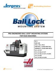
MountingSystem*HAAS is a trademark of HAAS Automation, <strong>Inc</strong>.1 <strong>BALL</strong> <strong>LOCK</strong> ® <strong>MOUNTING</strong> <strong>SYSTEM</strong>Pre-Engineered Ball Lock ® Fixture Kits for HAAS*www.jergensinc.comPRE-MACHINED FIXTURE/SUBPLATESBall LockBall Lock ® Mounting System<strong>Jergens</strong> Introduces Another Piece to the Quick Change PuzzleBall Lock ®Fixture KitsFor HAAS *HAAS models:• MINI MILL• VF-E• VF-O• VF-1• VF-OE• VF-2• VF-3• VF-4• VF-5Changes Fixtures in 60 SecondsKits for other machine ...or Lessmanufacturers available.Pre-Engineered HAAS Kitsavailable. PDF CatalogAvailable atwww.jergensinc.comThese kits include:• Steel Subplate with receiver bushings• Aluminum Fixture Plate(s) with 2 primary liner bushings• Pre installed receiver and Liner Bushings• Ball Lock ® Shanks• T-Slot nuts for mounting subplate to machine table• 2 Sine Fixture Keys for accurate subplate locating• Socket head cap screwsBenefits:• Save time specifying and ordering• Saves installation time and cost• Eliminates potential installation errorsAsk about these other machine manufacturers whereBall Lock ® kits can be utilized.Call customer support at 1-800-537-4367AcerBridgeportBrotherChevalierChironDMGEnshuExcelFanuc RobodrillHAASHardingeHitachiHitachi SeikiHurcoHyundai-KiaJohnsfordKira MillKitamuraLeadwellMAGMakinoMatsuuraMazakMilltronicsMiyanoMori-SeikiOKKOkumaRepublic LagunToyodaTreeYCI*HAAS is a trademark of HAAS Automation, <strong>Inc</strong>.1.14<strong>Jergens</strong>, <strong>Inc</strong>. • <strong>Jergens</strong> Way • 15700 S. Waterloo Road • Cleveland, Ohio 44110-3898 USA
www.jergensinc.com<strong>BALL</strong> <strong>LOCK</strong> ®<strong>MOUNTING</strong> <strong>SYSTEM</strong>1Set-Up Reduction WorksheetBenefits of Set-Up Reduction (Capacity)Current MethodMinutes per set-up = minutesNumber of set-upsper 8 hour shift = set-upsTotal minutes of set-up per shift(set-up minutes x number of set-ups) = minutesUsing the Ball Lock ® SystemMinutes per set-up = minutesExample (actual case study):60 minutes1.5 set-ups90 minutes8 minutesINCH PRE-MACHINED FIXTURE/SUBPLATESNumber of set-upsper 8 hour shift = set-upsTotal minutes of set-up per shift(set-up minutes x number of set-ups) = minutes<strong>Inc</strong>reased capacity per machine per shift(current method - Ball Lock ® method) = minutesSavings per machine per shift = minutes<strong>Inc</strong>reased capacity(number of minutes / 60) = hours1.5 set-ups12 minutes78 minutes78 minutes1.3 hoursBenefits of Set-Up Reduction (Profit)Machine cost per hour = $ $80.00<strong>Inc</strong>reased production hours per shift(increased capacity from above) = hours 1.3 hoursSavings (profit) per machine per shift(machine cost per hour x increased = $ per machine $104.00 per machineproduction hours) per shift per shiftPhone 800-537-4367 or +1 216-486-5540 • Fax: +1 216-481-6193 • E-mail: info@jergensinc.com • www.jergensinc.com 1.15
INCH PRE-MACHINED FIXTURE/SUBPLATES1 <strong>BALL</strong> <strong>LOCK</strong> ® <strong>MOUNTING</strong> <strong>SYSTEM</strong>INCH DIMENSIONSBall Lock ® For 4th Axis Rotary IndexersProblem:Rotary indexers increase the versatility of vertical machiningcenters, yet they offer one major challenge: set-up is so timeconsumingthat it may limit a machine’s flexibility. In many cases,machinists dedicate their 4th Axis tool to a single machine toavoid the agony of an extended set-up and changeover.Benefits:• Maximize indexer utilization• Eliminate lengthy set-ups• Accurate fixture plate changover in secondswww.jergensinc.comJergen’s Solution:Ball Lock ® Mounting System for Indexers provides a doublesolution.First, Ball Lock ® mounting plates free up your machine foradditional work by allowing a fast and accurate installationand removal of the complete indexer. Avoid hours of set up.The Ball Lock ® System does it in minutes, with repeatability at±.0005" (±.013mm). Low profile, positive clamping, proven inover many years of field use.Second, the Ball Lock ® System provides your fixture platechangeover. By mounting the round subplate to the indexerfaceplate, you’ll “plug-in” new fixtures in record time(less than 60 seconds).Indexer Face PlateBall Lock ®SubplateBall Lock ®ShanksBall Lock ®Fixture PlateFor HoldingProductionWorkpieceWorkpieceBall Lock ® Fixture PlateFor Mounting Indexerto Subplate andMachine TableSubplates and fixture plates come with bushings pre-installed.1.16<strong>Jergens</strong>, <strong>Inc</strong>. • <strong>Jergens</strong> Way • 15700 S. Waterloo Road • Cleveland, Ohio 44110-3898 USA
<strong>BALL</strong> <strong>LOCK</strong> ®<strong>MOUNTING</strong> <strong>SYSTEM</strong>INCH DIMENSIONSwww.jergensinc.comRound Ball Lock ® Fixture Plates and Subplates1Standard RoundCast Aluminum, FreeMax or Steel equivalentCustom Round PlatesFixture PlatePart Thickness Ball Lock ® Ball Lock ® WeightNo. A B ±0.005" Liner Shank (lbs)28707 8" 6" 3/4 16mm 49608 3.528708 10" 8" 1 20mm 49602 7.028709 12" 10" 1 20mm 49602 11.0SubplatePart Thickness Ball Lock ® Center WeightNo. A B ±0.005" Receiver Hole (lbs)49107 8" 6" 3/4 16mm 1.00" 11.049108 10" 8" 1 20mm 2.00" 21.049109 12" 10" 1 20mm 2.00" 33.0Metric sizes also available; please call for information.INCH PRE-MACHINED FIXTURE/SUBPLATESIndexer:Make:Model:Diameter:Light Duty or Heavy Duty:Through Hole Bore:CNC Machine:Make:Model:Weight Capacity:Indexer Faceplate:T-Slot Size:Configuration/Orientation:orDrilled Tapped Hole Size:Configuration/Orientation:Engineering ChangesProduct improvement is a continuing process at <strong>Jergens</strong>. Specifications and engineering data are subject to change without notice.If current information is critical to your design, it is suggested that you contact <strong>Jergens</strong> Technical Sales Department to verify anydimensions or specifications.Phone 800-537-4367 or +1 216-486-5540 • Fax: +1 216-481-6193 • E-mail: info@jergensinc.com • www.jergensinc.com 1.17
1 <strong>BALL</strong> <strong>LOCK</strong> ® <strong>MOUNTING</strong> <strong>SYSTEM</strong>INCH DIMENSIONSwww.jergensinc.comLocating and Clamping Shanks• Material: Shank/Bushing, 4340Liner, 52100• Finish: Black Oxide• Heat Treat: Shanks, RC 40-45Bushings, RC 50-54Liners, RC 62-64• Operating Temperature Range-20° to 400°F, -30° to 200°CDCBStainless Steel availableAINCH <strong>BALL</strong> <strong>LOCK</strong> ® COMPONENTSBall Lock ® Repair KitsEach Kit <strong>Inc</strong>ludes:• Replacement Screw• Locking Balls• Drive Ball• O-RingLocating and Clamping Shank DimensionsShankDiameter(mm)AFixturePlateThickness± 0.005ShankPartNumberHead of ShankHeightBDiameterCLengthUnder HeadDHex WrenchSize forSet ScrewAny Ball Lock ® application requires at least two sets ofshanks, receiver bushings and liners. The liners areplaced into the fixture plate to insure extremely accuratepositioning. If more than two shanks are required (toprovide additional hold down force), omit the linerbushing so that these additional holes will not interferewith your primary locating holes.See page 1.20 for Fast Acting Shanks.ScrewTorque(Ft/lb)MaximumHold-DownForce(lbs)RecommendedScrewTorque(Ft/lb)Hold-DownForce(lbs)ShankRepair KitPartNumber13 0.50 49605 0.25 0.87 1.08 3/32 1.2 750 1 625 499050.75 49606 1.33 4990616 0.50 49607 0.32 1.50 1.15 1/8 3 1200 2 800 499070.75 49608 1.40 4990820 0.75 49601 0.38 1.75 1.53 1/8 4 3000 3 2250 499011.00 49602 1.78 4990225 0.75 49611 0.38 2.00 1.70 5/32 9 7000 7 5444 499111.00 49612 1.95 4991230 0.75 49621 0.50 2.25 1.88 3/16 15 10000 12 8000 499211.00 49622 2.13 4992235 0.75 49631 0.50 2.25 1.97 1/4 25 15500 19 11780 499311.00 49632 2.22 499321.50 49633 2.72 499332.00 49634 3.22 4993450 0.75 49641 0.75 3.00 2.45 3/8 50 20000 38 15200 499411.00 49642 2.70 499421.50 49643 3.20 499432.00 49644 3.70 499441.18<strong>Jergens</strong>, <strong>Inc</strong>. • <strong>Jergens</strong> Way • 15700 S. Waterloo Road • Cleveland, Ohio 44110-3898 USA
www.jergensinc.com<strong>BALL</strong> <strong>LOCK</strong> ®<strong>MOUNTING</strong> <strong>SYSTEM</strong>INCH DIMENSIONS1Receiver BushingsTwo styles of receiver bushings are available.Generally, the face mount receiver bushing isutilized in blind hole applications (Slip Fit).The back mount receiver bushing is used inthrough hole applications (Light Press Fit).Note: Installed bushings should be approximately.012" below subplate surface.See reference below for installation of back mountstyle bushings.Back MountFace MountInstallation DimensionsFace MountShankDia.(mm)FaceMountPartNumberActualO.D.+0.0000-0.0004ClearanceDrillDiameterEBore+0.0005-0.0000FFace Mount BushingInstallation InstructionsDepth+0.002-0.000GTapSize &Depth 1H13 49506 1.3750 11/16 1.3750 0.469 8-32x5/16 0.98416 49507 1.4370 13/16 1.4370 0.469 8-32x5/16 1.12520 49501 1.6873 13/16 1.6873 0.637 10-32x3/8 1.36225 49502 2.0623 1 2.0623 0.799 1/4-28x1/2 1.64430 49503 2.2654 1 3/16 2.2654 0.871 1/4-28x3/4 1.87635 49504 2.6873 1 9/16 2.6873 0.904 5/16-24x7/8 2.17850 49505 3.4998 2 5/32 3.4998 1.239 3/8-24x1 2.916Cap Screws Supplied with Face Mount Bushings.1Bolt Circle Min.Diameter Subplate3 PL Equally ThicknessSpaced D3/43/411-1/41-3/81-1/22Back MountShankDia.(mm)Back Mount BushingInstallation InstructionsBackMountPartNumberActualO.D.+0.0000-0.0004ADepth+0.000-0.002BC-Bore±0.006C13 49516 0.7870 .277 1.00016 49517 0.8760 .285 1.15520 49511 1.0950 .345 1.28025 49512 1.3763 .416 1.59330 49513 1.6264 .432 1.90635 49514 1.8764 .493 2.15550 49515 2.6269 .621 2.988Min.SubplateThicknessD3/43/47/811-1/41-5/161-3/4INCH <strong>BALL</strong> <strong>LOCK</strong> ® COMPONENTSLiner Bushings for Fixture PlatesLiner DimensionsLocating repeatability will determine if one primary and onesecondary or two primary liners are needed. With two primaryliners, repeatability of ±.0005" can be maintained if the twoholes for receiver bushings are held to a centerline distanceof ±.0002" tolerance.Note on Installation of Press Fit Liners &Back Mount Style Receiver Bushings:To alleviate the possibility of binding theshank in the bore, the maximum interferencefit between bore and bushing O.D. should notexceed .0005".Fixture PlateThickness±0.005ShankDiameter(mm)PrimaryLinerPartNumberSecondaryLinerPartNumberLiner O.D.+0.0000-0.0004.50 13 49705 49805 0.7518.75 13 49706 49806 0.7518.50 16 49707 49807 1.0018.75 16 49708 49808 1.0018.75 20 49701 49801 1.37721.00 20 49702 49802 1.3772.75 25 49711 49811 1.37721.00 25 49712 49812 1.3772.75 30 49721 49821 1.7523Fixture PlateThickness±0.005ShankDiameter(mm)PrimaryLinerPartNumberSecondaryLinerPartNumberLiner O.D.+0.0000-0.00041.00 30 49722 49822 1.7523.75 35 49731 49831 1.75231.00 35 49732 49832 1.75231.50 35 49733 49833 1.75232.00 35 49734 49834 1.7523.75 50 49741 49841 2.50251.00 50 49742 49842 2.50251.50 50 49743 49843 2.50252.00 50 49744 49844 2.5025Phone 800-537-4367 or +1 216-486-5540 • Fax: +1 216-481-6193 • E-mail: info@jergensinc.com • www.jergensinc.com 1.19
1 <strong>BALL</strong> <strong>LOCK</strong> ® <strong>MOUNTING</strong> <strong>SYSTEM</strong>INCH DIMENSIONSAccessorieswww.jergensinc.comTapered Capsand PlugsKeep debris outof your subplate’sreceiver bushingswhen not in use.Polyethylene capssnap in and out easily.Packaged10 perpack.ReceiverBushing PartDiameter Number13 4920116 4920220 4920325 4920430 4920535 4920650 49207Lifting HandlesFor easy handling of fixture plates upto 500 lbs.Part Number Length Ht. W Mounting Distance33701 4.21 1.42 0.83 3.68Sine Fixture KeysINCH <strong>BALL</strong> <strong>LOCK</strong> ® COMPONENTSLocate subplates or fixtureplates to slotted machine tableswithout having to slot the plate.Available in inch sizes from 1/2"to 7/8" slots, and in metric sizesfrom 14mm to 22mm slots.NOTE: See page 4.21 fordimensions.Fast Acting Ball Lock ® ShanksBBTableTable SlotA Slot Size A Size (mm)Part +0.000 +0.000 Part +0.000 +0.000Number -0.0005 -0.0005 C Number -0.013 -0.013 C39501 .625 1/2 1 39562 16 14 139502 .625 9/16 1 39563 16 16 139503 .625 5/8 1 39564 16 18 139504 .625 11/16 1 39565 16 20 1-1/839505 .625 3/4 1-1/8 39566 16 22 1-1/839506 .625 13/16 1-1/839507 .625 7/8 1-1/8NOTE: All shanks are 5/8" diameterFast ActingBall Lock ®ShankDiameter(mm)FixturePlateThickness(in.)<strong>Jergens</strong> Ball Lock ® <strong>Jergens</strong> Ball Lock ®Shank w/<strong>Jergens</strong>ShankThumb ScrewAdjustable HandlePart NumberPart NumberAssembly T-Screw Assembly Handle16 1/2 49607-S 43904 49607-H 343143/4 49608-S 43904 49608-H 3431520 3/4 49601-S 43904 49601-H 343151 49602-S 43905 49602-H 3431625 3/4 49611-S 43907 49611-H 343281 49612-S 43908 49612-H 3432930 3/4 49621-S 43910 49621-H 343341 49622-S 43911 49622-H 3433535 3/4 49631-S 43913 49631-H 343391 49632-S 43913 49632-H 343391-1/2 49633-S 43914 N/A2 49634-S 43914 N/AThumbScrewAdjustableHandle• Fast acting thumbscrews 2 1/2 turns.No tools needed.• Handle can bemoved out of thework area to avoidinterference.1.20<strong>Jergens</strong>, <strong>Inc</strong>. • <strong>Jergens</strong> Way • 15700 S. Waterloo Road • Cleveland, Ohio 44110-3898 USA
www.jergensinc.comMulti-Purpose Subplate1000x500 Multi-Purpose SubplatePart Number Wt. (kg)59112 130The <strong>Jergens</strong> Multi-Purpose Subplateaccommodates a wide variety of fixture plates andvises. This versatility facilitates using the sameVMC for diverse products in repetitive runs-longand short batch sizes.<strong>BALL</strong> <strong>LOCK</strong> ®587065880169406<strong>MOUNTING</strong> <strong>SYSTEM</strong>METRIC DIMENSIONS1M• FreMax TM 15 Steel or Equivalent• Thickness: 31.75mm ±0.13mm• Parallel within 0.025mm58713 or 587155872759112425 425300 300(18) 20MM FACE MOUNTBUSHINGS I NSTALLED16MM BORED HOLEFOR SINE FIXTURE KEYS(2) PLACES(8) 25MM FACE MOUNTBUSHINGS I NSTALLEDFixture Plate Options for Multi-Purpose Subplates – Aluminum or Steel1000Number of Fixture Receiver Required NumberPlates/Vise That Mount Bushing Receiver Ball Lock ® of ShanksFixture Plate*/Vise Thickness of on Multi-Purpose Center Bushing Shank Required PerPart Number Fixture Plate Subplate Distance Size Part Number Fixture Plate/Vise200150300425500METRIC PRE-MACHINED FIXTURE/SUBPLATES58713 (350 x 350) 20mm 2 300 x 300 20 mm 49651 4Fixture Plate58715 (400 x 400) 20mm 2 300 x 300 20 mm 49651 4Fixture Plate58801 (400 x 400) 30mm** 2 300 x 300 20 mm 49652 4Modular Grid Plate58706 Jigsaw 20mm 4 300 x 200 20 mm 49651 3Interlocking Plate58727 (500 x 500) 25mm 2 425 x 425 25 mm 49662 4Fixture Plate69406 20mm 4 300 x 200 20 mm 49651 3150mm Jigsaw Vise* See next page for dimensional data on fixture plates. Part numbers shown for aluminum plates, also available in steel.** Counterbored to 25mm at mounting holes.Phone 800-537-4367 or +1 216-486-5540 • Fax: +1 216-481-6193 • E-mail: info@jergensinc.com • www.jergensinc.com 1.21
1M <strong>BALL</strong> <strong>LOCK</strong> ® <strong>MOUNTING</strong> <strong>SYSTEM</strong>METRIC DIMENSIONSFixture Plates for Use on Multi-Purpose Subplate350x350x20mm Fixture Platewww.jergensinc.com400x400 Modular Grid Fixture PlateAluminum PlatePart Number Wt. (kg)58713 6Steel PlatePart Number Wt. (kg)58813 19Aluminum PlatePart Number Wt. (kg)58801 38400x400 Fixture PlateAluminum PlatePart Number Wt. (kg)58715 8• Cast Aluminum or FreMax 15 Steel or equivalent• Thickness: 20mm ±0.13mm• Parallel within 0.025mm Steel• Mounts to subplates with BallLock ® Shank 49651 (20x20mm)300Steel PlatePart Number Wt. (kg)58815 25• FreMax 15 Steel or equivalent• Thickness: 28.57mm ±0.13mm• Parallel within 0.025mm Steel(2) 20MMPRIMARY LINERSINSTALLEDCLEARANCE HOLESFOR HOLDDOWN(2) PLACES16MM X 6MM DEEPCOUNTERBOREM12 X 1.75TAPPED HOLEMETRIC PRE-MACHINED FIXTURE/SUBPLATES300150CLEARANCE HOLESFOR HOLDDOWN(2) PLACES16MM BORED HOLEFOR SINE FIXTURE KEYS(2) PLACES(2) 20MMPRIMARY LINERSINSTALLEDJigsaw Interlocking FixturePlateAluminum PlatePart Number Wt. (kg)58706 4Steel PlatePart Number Wt. (kg)58806 12• Material: Cast Aluminum or FreMax 15 Steel or equivalent• Thickness: 20mm ±0.13mm• Parallel within 0.025mm Steel• For use with narrow base 100mm or 150mm vise models• Design allows close spacing of vises for more parts per run• Mounts to Subplates using Ball Lock ® Shank 44651 (20x20mm)• Useful for high density fixturing30040050TYP500x500x25mm Fixture PlateAluminum PlatePart Number Wt. (kg)58727 17• Cast Aluminum or FreMax 15 Steel or equivalent• Thickness: 25mm ±0.13mm• Parallel within 0.025mm Steel• Mounts to Subplates using Ball Lock ® Shank 49662 (25x25mm)500425300400Mounts to Subplatewith BallLock ® Shank49652 (20x25mm)Steel PlatePart Number Wt. (kg)58827 48CLEARANCE HOLE FORHOLDDOWN500 425CLEARANCE HOLESFOR HOLDDOWN(2) PLACES16MM BORED HOLEFOR SINE FIXTURE KEYS(2) PLACES250200(2) 20MMPRIMARY LINERSINSTALLED300150200212.50(2) 25MMPRIMARY LINERSINSTALLED4001.22<strong>Jergens</strong>, <strong>Inc</strong>. • <strong>Jergens</strong> Way • 15700 S. Waterloo Road • Cleveland, Ohio 44110-3898 USA
www.jergensinc.com<strong>BALL</strong> <strong>LOCK</strong> ®Pre-Machined Ball Lock ® Steel Subplate<strong>MOUNTING</strong> <strong>SYSTEM</strong>METRIC DIMENSIONS1M400400 x400 Subplate300Part Number Wt. (kg)59101 37(4) 20MMFACE MOUNT BUSHINGSINSTALLEDEquipped with four 20mm receiver bushings for use with350x350 or 400x400 (mm) fixture plates. Ideal for horizontalmachining centers or multiple pallet machining centers.40030015016MM BORED HOLEFOR SINE FIXTURE KEYS(2) PLACES• FreMax 15 steel plate or equivalent• Thickness: 28.57mm ±0.13mm• Parallel within 0.025mm25025650325650x400 Dual Station SubplatePart Number Wt. (kg)59111 5840030015016MM BORED HOLEFOR SINE FIXTURE KEYS(2) PLACESAluminum Steel Plate Number PlatePlate Part Part of Fixture Width andNumber Number Plates Length (mm)58713 58813 1 350x35058715 58815 1 400x40058711 58811 2 300x350150300(12) 20MMFACE MOUNT BUSHINGSINSTALLEDEquipped with twelve installed 20mm receiverbushings to easily locate and mount <strong>Jergens</strong>Standard Fixture Plates.• Ideal for vertical machining centers• Thickness: 28.57mm ±0.13mm• Parallel within 0.025mm58713 or587155871159111METRIC PRE-MACHINED FIXTURE/SUBPLATES20˚˚˚˚16mm Bored Holes ForSine Fixture Keys(2) Places12mm Dia. For Mounting ToTable (4) Places(4) 16mm Face MountBushings Installed300˚˚˚63.5200 25063.5˚250x375 Bridgeport - Style SubplatePart Number Wt. (kg)59121 15Equipped with four installed 16mm receiver bushings and12mm mounting holes. Used with the Bridgeport stylefixture plates 58731 or 58831.• Thickness: 19.05mm ±0.13mm• Parallel within 0.025mm375Ball Lock ® Quick Change Kits include all components needed in a single package. See page 1.25 for details.Phone 800-537-4367 or +1 216-486-5540 • Fax: +1 216-481-6193 • E-mail: info@jergensinc.com • www.jergensinc.com 1.23
1M <strong>BALL</strong> <strong>LOCK</strong> ® <strong>MOUNTING</strong> <strong>SYSTEM</strong>METRIC DIMENSIONSBall Lock ® Fixture Plates• Cast Aluminum; or FreMax 15 Steel or equivalent• Thickness ±0.13mm• Parallel within .025mm Steel• 6061–T-651 plates, flat within 0.03mm available upon requestBall Lock ® Fixture Plates with 2 Primary Liners InstalledPart NumberWeightWeightAluminum (Kgs) Steel (Kgs)PlateDimensions(mm)PlateThickness±0.13(mm)Ball Lock ®Shank Size(mm)Ball Lock ®Shank PartNumber58706 4 58806 12 250 x400 20 20 4965158711 5 58811 16 300 x350 20 20 4965158713 6 58813 19 350 x 350 20 20 4965158715 8 58815 25 400 x 400 20 20 4965158727 17 58827 48 500 x 500 25 25 4966258801 38 400 x 400 28.57 20 4965258731 5 58831 15 375x250 20 16 49657www.jergensinc.com• Machined to close tolerances• Repeatability ±0.013mm or better• Reduces fixture set-up andassembly time• Provided with 16mm bored holesfor sine fixture keys• For horizontal or verticalmachining centers, Tool RoomMills machines, or multiple palletmachining centersMETRIC PRE-MACHINED FIXTURE/SUBPLATESCustom Sizes Available<strong>Jergens</strong> will make Ball Lock ® fixture plates or subplates to yourspecifications. Call 1-216-486-5540 for further information.375x250x20mm Fixture Plate Bridgeport StyleAluminum PlatePart Number Wt. (kg)58731 5Steel PlatePart Number Wt. (kg)58831 15300x350x20mm Fixture PlateAluminum PlatePart Number Wt. (kg)58711 5Steel PlatePart Number Wt. (kg)58811 16Clearance Hole ForHolddown (2) Places30025010016mm Bored Holes ForSine Fixture Keys(2) Places(2) 16mm PrimaryLiners Installed300375200250350 300150Clearance Holes ForHolddown (2) Places16mm Bored HolesFor Sine Fixture Keys(2) Places(2) 20mm PrimaryLiners Installed1.24<strong>Jergens</strong>, <strong>Inc</strong>. • <strong>Jergens</strong> Way • 15700 S. Waterloo Road • Cleveland, Ohio 44110-3898 USA
www.jergensinc.com<strong>BALL</strong> <strong>LOCK</strong> ®<strong>MOUNTING</strong> <strong>SYSTEM</strong>METRIC DIMENSIONS1MQuick Change KitsThe <strong>Jergens</strong> Ball Lock ® Quick Change Kits speed fixture changeover inall types of manufacturing operations. Each kit includes two aluminumfixture plates with 2 primary liner bushings installed; one steel subplatewith receiver bushings installed, and four 20mm Ball Lock ® shankswith working loads of 3000 lbs. each. While one fixture plate is on themachine, the operator can load parts on the other. This minimizesdowntime for true set-up reduction. To enable the subplate to bemounted on a slotted table without the need to indicate the subplate,sine fixture keys can be used. The sine fixture key reamed holes areoriented parallel to the receiver bushings on the subplate and to theliner bushings on the fixture plate. These also allow the fixture plateto be mounted on a toolroom millwithout the need to indicate it. Thisis extremely useful when machininglocation points on your fixture.Everything You Need to Change Fixtures in Less Than One MinuteAluminumFixture Plate16mm BoredHole for SineFixture Keys20mm Ball Lock ®ShankQuick Change KitsPart No.Kit <strong>Inc</strong>ludes59002 2 - 58715 (400x400x20) aluminumfixture plates with 20mm linerbushings installed1 - 59101 (400x400x25) steel subplatewith receiver bushings installed4 - 20mm Ball Lock ® Shanks (49651)METRIC PRE-MACHINED FIXTURE/SUBPLATESSteel Subplate16mm BoredHole for SineFixture Keys(2) 20mm Primary LinerBushings Installed(4) 20mmReceiverBushingsInstalledCustom Kits Available<strong>Jergens</strong> manufactures ready to use kits includingBall Lock ® subplate and fixture plates.For a special kit tailored to your CNC machine,please provide:Name and Type of Machine __________________Travel of Machine Table (x, y, z) ______________Dimensions of Machine Table (x and y) _________Maximum Weight allowed on Machine Table _____T-slot Width and Center to Center Distance _____Phone 800-537-4367 or +1 216-486-5540 • Fax: +1 216-481-6193 • E-mail: info@jergensinc.com • www.jergensinc.com 1.25
1M <strong>BALL</strong> <strong>LOCK</strong> ® <strong>MOUNTING</strong> <strong>SYSTEM</strong>METRIC DIMENSIONSPre-Machined Ball Lock ® T-Columns• Class 40 Cast Iron• Also available in Aluminum• Ball Lock ® Receiver Bushings and Liners installed• Provides accurate fixturing base for CNC machining centers• Perpendicularity is 0.025 mm per 250 mmwww.jergensinc.comFixturePlateCustom Sizes Available with or without Ball Lock ®We are able to quote you on your special requirementwith or without the Ball Lock ® Mounting System.Call 1-216-486-5540 for design specification information.SubplateToolingColumnMETRIC PRE-MACHINED TOOLING COLUMNSCast Iron T-Columns WithBall Lock ® Receiver Bushings InstalledPallet Part O P Wt.Size (mm) Number C D E F G H I J K L M N (mm) (mm) (kg)400 69151 410 25 400 400 350 350 350 350 100 500 125 90 20 20 190500 69161 560 25 500 500 475 425 425 425 120 650 137.5 90 25 25 310630 69171 660 40 630 630 575 550 525 525 100 750 137.5 90 35 25 500M12See page 1.28 for Metric Fixture Plates and Subplates*Note: Window sections are also available on T-Columns. Specify window size and location (Q and R Dimensions).Corresponding Fixture Plates, Subplates and Ball Lock ® ShanksPallet T-Column Aluminum Steel Fixture Fixture Plate SubplateSize Part Fixture Plate Fixture Plate Plate Ball Lock ® Shank Shank Subplate Ball Lock ® Shank Shank(mm) Number Part Number Part Number Size Part Number Size Part Number Part Number Size400 69151 58717 58817 400 x 400 49651 20 x 20 59102 49652 20 x 25500 69161 58745 58845 500 x 550 49662 25 x 25 59103 49662 25 x 25630 69171 58746 58846 625 x 650 49662 25 x 25 59104 49683 35 x 40Use Hoist Ring 23462, see page 11.9 for lifting and handling – Order separately.Engineering ChangesProduct improvement is a continuing process at <strong>Jergens</strong>. Specifications and engineering data are subject to changeafter publishing. Contact <strong>Jergens</strong> Technical Sales Department to verify any dimensions or specifications.1.26<strong>Jergens</strong>, <strong>Inc</strong>. • <strong>Jergens</strong> Way • 15700 S. Waterloo Road • Cleveland, Ohio 44110-3898 USA
www.jergensinc.com<strong>BALL</strong> <strong>LOCK</strong> ®<strong>MOUNTING</strong> <strong>SYSTEM</strong>METRIC DIMENSIONS1MPre-Machined Ball Lock ® 4-Sided Tooling Columns• Class 40 cast iron• Also available in Aluminum• Ball Lock ® Receiver Bushings and Liner Bushings installed• Provides accurate fixturing base for CNC machining centers• Perpendicularity is 0.025 mm per 250 mmToolingColumnFixturePlateCustom Sizes Available with or without Ball Lock ®We are able to quote you on your special requirementwith or without the Ball Lock ® Mounting System.Call 1-216-486-5540 for design specification information.SubplateCast Iron 4-Sided Tooling Columns WithBall Lock ® Receiver Bushings InstalledSee page 1.26 for Metric Fixture and SubplatesPallet Part O P Wt.Size (mm) Number A B C D E F G H I J K L M N (mm) (mm) (kg)400 69051 250 250 505 25 400 400 450 150 350 350 40 600 125 95 20 20 225500 69061 300 300 630 25 500 500 550 175 425 425 40 725 137.5 95 25 25 320630 69071 400 400 655 40 630 630 575 275 525 525 45 750 137.5 95 35 25 495M12METRIC PRE-MACHINED TOOLING COLUMNSCorresponding Fixture Plates, Subplates and Ball Lock ® ShanksPallet T-Column Aluminum Steel Fixture Fixture Plate SubplateSize Part Fixture Plate Fixture Plate Plate Ball Lock ® Shank Shank Subplate Ball Lock ® Shank Shank(mm) Number Part Number Part Number Size Part Number Size Part Number Part Number Size400 69051 58741 58841 250 x 500 49651 20 x 20 59102 49652 20 x 25500 69061 58742 58842 300 x 625 49662 25 x 25 59103 49662 25 x 25630 69071 58743 58843 400 x 650 49662 25 x 25 59104 49683 35 x 40Use Hoist Ring 23462, see page 11.9 for lifting and handling – Order separately.Engineering ChangesProduct improvement is a continuing process at <strong>Jergens</strong>. Specifications and engineering data are subject tochange after publishing. Contact <strong>Jergens</strong> Technical Sales Department to verify any dimensions or specifications.Phone 800-537-4367 or +1 216-486-5540 • Fax: +1 216-481-6193 • E-mail: info@jergensinc.com • www.jergensinc.com 1.27
1M <strong>BALL</strong> <strong>LOCK</strong> ® <strong>MOUNTING</strong> <strong>SYSTEM</strong>METRIC DIMENSIONSSubplates for Tooling Columns and Fixture Plates16mm Bored holesfor sine fixturekeys (2) placesReceiverBushingsABStandard Steel Subplates for Tooling ColumnsSubplate Mounting holes can be provided per customer specification.Supplied with Ball Lock ® Receiver Bushings installed.www.jergensinc.comBall Lock ® Pattern Receiver Thickness ofPart Pallet Size For Tooling A B Size Subplate WtNumber (mm) Columns (mm) (mm) (mm) (mm) ±0.13 (Kgs)59102 400 69151/69051 350 350 20 28.57 3159103 500 69161/69061 425 425 25 31.75 5959103-C* 500 69151, 69051 350/425 350/425 20/25 31.75 5969161, 69061 Dual Dual Dual59104 630 69171/69071 525 525 35 34.92 124METRIC PRE-MACHINED FIXTURE/SUBPLATES16mm Bored holesfor sine fixture keys(2) placesPrimaryLiners16mm Bored holesfor sine fixture keys(2) placesJEPrimaryLinersFixture Plates for Standard Tooling Columns and T-ColumnsSupplied with 2 primary Ball Lock ® Liner Bushings installed.Fixture Fixture Plate Ball Lock ® Pattern LinerPallet Part Number For Tooling Plate Size Thickness H G SizeSize (mm) Aluminum (kg) Steel (kg) Columns Type (mm) (mm) ±0.13 (mm) (mm) (mm)400 58741 7 58841 19 69051 4-S 250x500 150 450 20 20I500 58742 13 58842 36 69061 4-S 300x625 175 550 25 25630 58743 18 58843 50 69071 4-S 400x650 275 575 25 25400 58717 8 58817 25 69151 T 400x400 350 350 20 20500 58745 19 58845 53 69161 T 500x550 425 475 25 25630 58746 27 58846 63 69171 T 625x650 550 575 25 25FFixture Plates for Tooling Column SubplatesSupplied with 2 primary Ball Lock ® Liner Bushings installed.Ball Lock ®Pallet Part Number Plate Dim. Fixture Plate Pattern LinerSize For E F Thickness I J Size(mm) Aluminum (kg) Steel (kg) Subplate (mm) (mm) ±0.13 (mm) (mm) (mm) (mm)400 58717 8 58817 25 59102 400 400 20 350 350 20500 58727 17 58827 48 59103 500 500 25 425 425 25630 58732 27 58832 76 59104 630 630 25 525 525 35Difference between Aluminum and Steel( mm )0.00150.001250.0010.000750.00050.0002500Aluminum and Steel Expansion(per cm )2.8 5.4 8.4 11.2 14 16.8Change in Degrees CNOTE: Aluminum and steel expand at different rates. Please take this information into considerationwhen creating your own Ball Lock ® fixture and subplates.1.28<strong>Jergens</strong>, <strong>Inc</strong>. • <strong>Jergens</strong> Way • 15700 S. Waterloo Road • Cleveland, Ohio 44110-3898 USA
www.jergensinc.com<strong>BALL</strong> <strong>LOCK</strong> ®Ball Lock® For 4th Axis Rotary IndexersProblem:Rotary indexers increase the versatility of vertical machiningcenters, yet they offer one major challenge: set-up is so timeconsumingthat it may limit a machine’s flexibility. In many cases,machinists dedicate their 4th Axis tool to a single machine toavoid the agony of an extended set-up and changeover.Benefits:• Maximize indexer utilization• Eliminate lengthy set-ups• Accurate fixture plate changover in seconds<strong>MOUNTING</strong> <strong>SYSTEM</strong>METRIC DIMENSIONS1MJergen’s Solution:Ball Lock ® Mounting System for Indexers provides a doublesolution.First, Ball Lock ® mounting plates free up your machine foradditional work by allowing a fast and accurate installationand removal of the complete indexer. Avoid hours of set up.The Ball Lock ® System does it in minutes, with repeatability at±.0005" (±.013mm). Low profile, positive clamping, proven inover many years of field use.Second, the Ball Lock ® System provides your fixture platechangeover. By mounting the round subplate to the indexerfaceplate, you’ll “plug-in” new fixtures in record time(less than 60 seconds).Indexer Face PlateBall Lock ®Fixture PlateFor HoldingProductionWorkpieceBall Lock ®ShanksBall Lock ®SubplateMETRIC PRE-MACHINED FIXTURE/SUBPLATESWorkpieceBall Lock ® Fixture PlateFor Mounting Indexerto Subplate andMachine TableSubplates and fixture plates come with bushings pre-installed.Phone 800-537-4367 or +1 216-486-5540 • Fax: +1 216-481-6193 • E-mail: info@jergensinc.com • www.jergensinc.com 1.29
1M <strong>BALL</strong> <strong>LOCK</strong> ® <strong>MOUNTING</strong> <strong>SYSTEM</strong>METRIC DIMENSIONSwww.jergensinc.comRound Ball Lock ® Fixture Plates and SubplatesStandard RoundCast Aluminum, FreeMax or Steel equivalentFixture Plate (mm)Part Ball Lock ® Ball Lock ® WeightNo. A B Thickness Liner Shank (Kgs)58707 200 150 20 16 49657 1.658708 250 200 25 20 49652 3.258709 300 250 25 20 49652 5.0Subplate(mm)Part Ball Lock ® Center WeightNo. A B Thickness Receiver Hole (Kgs)59107 200 150 20 16 25 5.059108 250 200 25 20 50 9.659109 300 250 25 20 50 15.0Note: Equivalent system available in inch dimensions.Custom Round PlatesMETRIC PRE-MACHINED FIXTURE/SUBPLATESIndexer:Make:Model:Diameter:Light Duty or Heavy Duty:Through Hole Bore:CNC Machine:Make:Model:Weight Capacity:Indexer Faceplate:T-Slot Size:Configuration/Orientation:orDrilled Tapped Hole Size:Configuration/Orientation:Engineering ChangesProduct improvement is a continuing process at <strong>Jergens</strong>. Specifications and engineering data are subject to change withoutnotice. If current information is critical to your design, it is suggested that you contact <strong>Jergens</strong> Technical Sales Department toverify any dimensions or specifications.1.30<strong>Jergens</strong>, <strong>Inc</strong>. • <strong>Jergens</strong> Way • 15700 S. Waterloo Road • Cleveland, Ohio 44110-3898 USA
www.jergensinc.com<strong>BALL</strong> <strong>LOCK</strong> ®Locating and Clamping Shanks<strong>MOUNTING</strong> <strong>SYSTEM</strong>METRIC DIMENSIONS1MU.S. Patents: 3,498,6534,135,418Replacement KitsLocating and Clamping Shank DimensionsShankDiameter(mm)A13162025303550FixturePlateThickness±0.13mm132020252025202520252025405020254050• Material: Shank/Bushing, AISI 4340Liner, 52100• Finish: Black Oxide• Heat Treat: Shanks, RC 40-45Bushings, RC 50-54Liners, RC 62-64• Operating Temperature Range:-30°C to 200°C• Stainless Steel availableHead of ShankShankPartHeight DiameterNumber B C D49655496564965749658496514965249661496624967149672496814968249683496844969149692496934969468101013132022324045506075Each Kit <strong>Inc</strong>ludes:• Replacement Screw• Locking Balls• Drive Ball• O-Ring27.634.636.541.539.544.544.049.049.054.051.056.071.081.064.069.084.094.0HexWrench SizeForSet Screw2.53345610DCAAny Ball Lock ® application requires at least two sets ofshanks, receiver bushings and liners. The liners areplaced into the fixture plate to insure extremely accuratepositioning. If more than two shanks are required (toprovide additional hold down force), omit the liner bushingso that these additional holes will not interfere with yourprimary locating holes.See page 1.33 for Fast Acting Shanks.MaximumScrew HolddownTorque Force(N.m) (KN)1.2 3.34.55.3111833655.313.330446888BRecommendedScrew HolddownTorque Force(N.m) (KN)1 2.73491525503.51023355267ShankRepair KitPartNumber499554995649957499584995149952499614996249971499724998149982499834998449991499924999349994METRIC <strong>BALL</strong> <strong>LOCK</strong> ® COMPONENTSPhone 800-537-4367 or +1 216-486-5540 • Fax: +1 216-481-6193 • E-mail: info@jergensinc.com • www.jergensinc.com 1.31
1M <strong>BALL</strong> <strong>LOCK</strong> ® <strong>MOUNTING</strong> <strong>SYSTEM</strong>METRIC DIMENSIONSReceiver Bushingswww.jergensinc.comTwo styles of receiver bushings are available. Installed bushings should be approximately 0.3mm below subplate surface.Max. CornerRadius 0.5mmFace MountBack MountMax. CornerRadius 0.5mmH - Tap 3 HolesEqually SpacedOn Bolt Circle Dia.Face Mount BushingInstallation InstructionsBack Mount BushingInstallation InstructionsMETRIC <strong>BALL</strong> <strong>LOCK</strong> ® COMPONENTSGenerally, the face mount receiver bushing is utilized in blind holeapplications (Slip Fit).Installation DimensionsFace MountShankDia.(mm)13162025303550FaceMountPartNumber49556495574955149552495534955449555ActualO.D.-0.01-0.0235374555607092ClearanceDrillDiameterE13.521.021.025.530.540.055.0Bore+0.010+0.003F353745556070921Cap Screws Supplied with Face Mount Bushings.Liner Bushings forFixture PlatesDepth+0.025-0.025G11.9111.9116.2120.3222.1522.9931.50Note on Installation of Press Fit Liners &Back Mount Style Receiver Bushings:To alleviate the possibility of binding theshank in the bore, the maximum interferencefit between bore and bushing O.D. should notexceed 0.013 mm.TapSize &Depth 1HM4x0.7 x 7M4x0.7 x 7M5x0.8 x 9M6x1.0 x 10M6x1.0 x 11M8x1.25 x 17M10x1.5 x 18Locating repeatability will determine if one primaryand one secondary or two primary liners are needed.With two primary liners, repeatability of ±0.013 mm canbe maintained if the two holes for receiver bushings areheld to a centerline distance of ±0.005 mm tolerance.Bolt CircleDiameter3 PL EquallySpaced25293542485675Min.SubplateThicknessD20202530354050Liner DimensionsShankDiameter(mm)13162025303550Fixture PlateThickness+0.13- 0.13132020252025202520252025405020254050The back mount receiver bushing is used in through holeapplications (Light Press Fit).Back MountShankDia.(mm)13162025303550497554975649757497584975149752497614976249771497724978149782497834978449791497924979349794BackMountPartNumber49566495674956149562495634956449565Primary LinerPart NumberI.D.13.0116.0120.0125.0130.0135.0150.01ActualO.D.+0.04+0.03A20222835424867498554985649857498584985149852498614986249871498724988149882498834988449891498924989349894Depth+0.025-0.025B6.927.248.7410.5410.9512.5015.75Secondary LinerPart NumberI.D.13.0416.0420.0425.0430.0435.0450.04C-Bore± 0.15C26293341495576Min.SubplateThicknessD20202525303545Liner O.D.+0.00- 0.0119.04019.04025.04225.04235.04235.04235.04235.04245.04245.04245.04245.04245.04245.04263.54663.54663.54663.5461.32<strong>Jergens</strong>, <strong>Inc</strong>. • <strong>Jergens</strong> Way • 15700 S. Waterloo Road • Cleveland, Ohio 44110-3898 USA
www.jergensinc.comAccessoriesTapered Capsand PlugsKeep debris out of yoursubplate’s receiverbushings when not inuse. Polyethylene capssnap in and out easily.Packaged10 perpack.<strong>BALL</strong> <strong>LOCK</strong> ®ReceiverBushing PartDiameter Number13 4920116 4920220 4920325 4920430 4920535 4920650 49207<strong>MOUNTING</strong> <strong>SYSTEM</strong>METRIC DIMENSIONSLifting HandlesFor easy handling of fixture plates upto 500 lbs.1MPart Number Length Ht. W Mounting Distance33701 107mm 36mm .38kg 93.47mmSine Fixture KeysShank SlotPart Size Size Wt.Number A B C (kg)39551 16 12 25 .0439552 16 14 25 .0539553 16 16 25 .0539554 16 18 29 .0539555 16 20 29 .0639556 16 22 29 .0639557 20 24 35 .0739558 20 28 35 .1039559 20 32 40 .10RecommendedHole Diameter16mm Shank Size:16.01 ± 0.0120mm Shank Size:20.01 ± 0.01Locate subplates or fixture plates toslotted machine tables without havingto slot the plate. Available in sizes from12mm to 32mm slots.METRIC <strong>BALL</strong> <strong>LOCK</strong> ® COMPONENTSFast Acting Ball Lock ® ShanksFast Acting Ball Lock ® ShanksBall Lock ®ShankDiameter(mm)FixturePlateThickness(mm)Shank withThumb ScrewShank withAdjustable HandlePart NumberPart NumberAssenbly T-Screw Assenbly Handle13 13 49655-S 43971 49655-H 3436020 49656-S 43972 49656-H 3436116 20 49657-S 43974 49657-H 3436525 49658-S 43975 49658-H 3436520 20 49651-S 43974 49651-H 3436525 49652-S 43975 49652-H 3436525 20 49661-S 43977 49661-H 3437825 49662-S 43978 49662-H 3437930 20 49671-S 43980 49671-H 3438525 49672-S 43980 49672-H 3438535 20 49681-S 43985 49681-H 3439325 49682-S 43985 49682-H 34393ThumbScrewAdjustableHandle• Fast acting thumbscrews 2 1/2 turns.No tools needed.• Handle can bemoved out of thework area to avoidinterference.Phone 800-537-4367 or +1 216-486-5540 • Fax: +1 216-481-6193 • E-mail: info@jergensinc.com • www.jergensinc.com 1.33