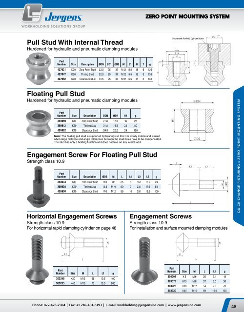
ZERO POINT MOUNTING SYSTEMWORKHOLDING SOLUTIONS GROUPPull Stud With Internal ThreadHardened for hydraulic and pneumatic clamping modulesPartNumber Size Description ØDN ØD1 ØD2 M S1 U T g427021 K20 <strong>Zero</strong> <strong>Point</strong> Stud 32.0 25 37 M12 5.5 18 5 136427047 K20 Timing Stud 32.0 25 37 M12 5.5 18 5 136427062 K20 Clearance Stud 31.6 25 37 M12 5.5 18 5 136Floating Pull StudHardened for hydraulic and pneumatic clamping modulesPartNumber Size Description ØDN ØD2 H1 g340059 K10 <strong>Zero</strong> <strong>Point</strong> Stud 21.8 12.0 16 25305912 K20 Timing Stud 31.8 15.5 23 80426882 K40 Clearance Stud 39.8 20.0 29 160Note: The floating pull stud is supported by bearings so that it is axially mobile and is usedwhen large distance and angle tolerances between <strong>the</strong> stud holes have to be compensated.The stud has only a holding function and does not take on any lateral load.Engagement Screw For Floating Pull StudStrength class 10.9PartNumber Size Description ØD2 M L L1 L2 L3 g340034 K10 <strong>Zero</strong> <strong>Point</strong> Stud 11.0 M8 35 6 16.1 12.9 24305938 K20 Timing Stud 13.5 M10 50 9 23.1 17.9 55426908 K40 Clearance Stud 17.0 M12 59 10 29.1 19.9 100Horizontal Engagement ScrewsStrength class 10.9For horizontal rapid clamping cylinder on page 48Engagement ScrewsStrength class 10.9For installation and surface mounted clamping modulesQUICK CHANGE FIXTURING » ZERO POINT MOUNTING SYSTEMPartNumber Size M L L1 g303248 K20 M12 56 10.5 100303255 K40 M16 73 13.0 200PartNumber Size M L L1 g306092 K 5 M 6 25 3.4 18303578 K10 M 8 37 6.0 30303222 K20 M12 54 9.0 70303230 K40 M16 69 10.0 130Phone: 877-426-2504 | Fax: +1 216-481-6193 | E-mail: workholding@jergensinc.com | www.jergensinc.com45
ZERO POINT MOUNTING SYSTEMWORKHOLDING SOLUTIONS GROUPThreaded Clamping Modules (K5)Round, Screw-In VersionHydraulic UnlockingCover and piston hardened.Repeatability < 0.005 mm (0.0002")With a small footprint for installation in baseplates, machine tables, clamping pr<strong>of</strong>iles,columns and towers, swivel bridges, machinepallets and clamping pallets.• Installation diagrams on requestQUICK CHANGE FIXTURING » ZERO POINT MOUNTING SYSTEMHardened Stainless SteelPart Size Pull-In/Locking Holding ForceNumber Force up to kN / (lbs) kN / (lbs) ØD ØDN ØD1 H HA ØLK T g480244 K5 5 / (1100) 13 / (2900) M45 x 1 15 39 19.8 5.8 36 14 300All linear dimensions in (mm)Note: Threaded clamping module with a low installation height <strong>of</strong> 19.8 mm and an installation diameter <strong>of</strong> 45 mm (M45 x 1).Hydraulic supply and pressure is only needed for unclamping (min. 50 bar / 725psi, max. 60 bar / 870psi). The threaded clamping module is mechanically lockedin <strong>the</strong> clamped position. The unique mechanical locking system results in virtually no vibration even with extensive machining forces. Fur<strong>the</strong>r more, <strong>the</strong>re are nocumbersome lines or dangers <strong>of</strong> leakage. The contact surface is <strong>the</strong> upper surface <strong>of</strong> <strong>the</strong> housing. The hydraulic design has 1 connection: 1 x unclampingRound, Screw-in VersionPneumatic UnlockingCover and piston hardened.Repeatability < 0.005 mm (0.0002")With a small footprint for installation in baseplates, machine tables, clamping pr<strong>of</strong>iles,columns and towers, swivel bridges, machinepallets and clamping pallets. Pneumaticmodules are optimally suited for use in <strong>the</strong>food, pharmaceutical and chemical industries,as well as in oil-free applications.• Installation diagrams on requestHardened Stainless SteelPart Size Pull-In/Locking Holding ForceNumber Force up to kN / (lbs) kN / (lbs) ØD ØDN ØD1 H HA ØLK T g480343 K5 1.5 / (330) 13 / (2900) M45 x 1 15 39 19.8 5.8 36 14 300All linear dimensions in (mm)Note: Threaded clamping module with a low installation height <strong>of</strong> 19.8 mm and an installation diameter <strong>of</strong> 45 mm (M45 x 1).Pneumatic pressure is needed for unclamping ( min 8 bar/ 116 psi, max 12 bar/ 175 psi). For clamping process pneumatic pressure <strong>of</strong> min 5 bar / 75 psi, max 6bar / 90 psi is required briefly in order to achieve defined pull-in force. The threaded clamping module is mechanically locked in <strong>the</strong> clamped position. The uniquemechanical locking system results in virtually no vibration even with extensive machining forces. Fur<strong>the</strong>r more, <strong>the</strong>re are no cumbersome lines or dangers <strong>of</strong> leakage.The pneumatic design has 2 connections: 1 x unclamping / 1 x clamping.46<strong>Jergens</strong>, <strong>Inc</strong>. | 15700 S. Waterloo Road | Cleveland, Ohio 44110-3898 USA