Manual - Busy Bee Tools
Manual - Busy Bee Tools
Manual - Busy Bee Tools
Create successful ePaper yourself
Turn your PDF publications into a flip-book with our unique Google optimized e-Paper software.
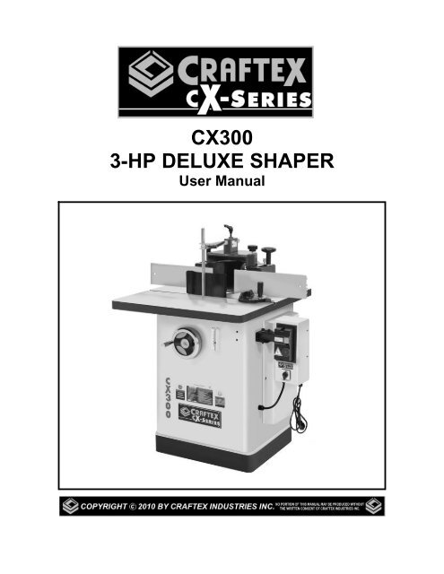
CX300<br />
3-HP DELUXE SHAPER<br />
User <strong>Manual</strong>
TABLE OF CONTENTS<br />
General Safety Instructions.....................................................................................3<br />
Specific Safety Instructions.....................................................................................4<br />
CX300 Features......................................................................................................5<br />
Physical Features ...................................................................................................6<br />
Set Up.....................................................................................................................7<br />
Un-Packing .............................................................................................................7<br />
Proper Grounding ...................................................................................................8<br />
Assembly ................................................................................................................9<br />
Spindle....................................................................................................................10<br />
Table Insert.............................................................................................................11<br />
Fence Assembly .....................................................................................................12<br />
Cutter-Head Guard .................................................................................................12<br />
Connecting to a Dust Collector ...............................................................................13<br />
Basic Controls.........................................................................................................14<br />
Test Run .................................................................................................................14<br />
Forward / Reverse Switch.......................................................................................15<br />
Installing the Cutter.................................................................................................15<br />
Spindle Height ........................................................................................................16<br />
Fence Adjustment...................................................................................................16<br />
Speed Changes ......................................................................................................17<br />
Replacing the V-Belt ...............................................................................................17<br />
Tensioning the V-Belt..............................................................................................18<br />
Shaping with the Fence ..........................................................................................18<br />
Free Hand Shaping.................................................................................................19<br />
Using Collars ..........................................................................................................19<br />
Maintenance ...........................................................................................................20<br />
Lubrication ..............................................................................................................20<br />
Cleaning..................................................................................................................20<br />
V-Belt Inspection.....................................................................................................20<br />
Troubleshooting ......................................................................................................21<br />
Parts Breakdown & List.......................................................................................22-31<br />
Warranty .................................................................................................................32<br />
2
GENERALSAFETY INSTRUCTIONS<br />
FOR MACHINES<br />
Extreme caution should be used when operating all power tools. Know your power<br />
tool, be familiar with its operation, read through the user manual and practice safe<br />
usage procedures at all times.<br />
ALWAYS read and understand the<br />
user manual before operating the<br />
machine.<br />
CONNECT your machine ONLY to the<br />
matched and specific power source.<br />
ALWAYS wear safety glasses<br />
respirators, hearing protection and<br />
safety shoes, when operating your<br />
machine.<br />
DO NOT wear loose clothing or<br />
jewelry when operating your machine.<br />
A SAFE ENVIRONMENT is<br />
important. Keep the area free of dust,<br />
dirt and other debris in the immediate<br />
vicinity of your machine.<br />
BE ALERT! DO NOT use prescription<br />
or other drugs that may affect your<br />
ability or judgment to safely use your<br />
machine.<br />
DISCONNECT the power source when<br />
changing drill bits, hollow chisels,<br />
router bits, shaper heads, blades,<br />
knives or making other adjustments or<br />
repairs.<br />
NEVER leave a tool unattended while it<br />
is in operation.<br />
NEVER reach over the table when the<br />
tool is in operation.<br />
ALWAYS keep blades, knives and bits<br />
sharpened and properly aligned.<br />
ALL OPERATIONS MUST BE<br />
performed with the guards in place to<br />
ensure safety.<br />
ALWAYS use push sticks and feather<br />
boards to safely feed your work through<br />
the machine and clamp the work-piece<br />
(when necessary) to prevent the workpiece<br />
from any unexpected movement.<br />
ALWAYS make sure that any tools used<br />
for adjustments are removed before<br />
operating the machine.<br />
ALWAYS keep the bystanders safely<br />
away while the machine is in operation.<br />
NEVER attempt to remove jammed<br />
cutoff pieces until the saw blade has<br />
come to a full stop.<br />
3
CX300 – DELUXE SHAPER<br />
SPECIFIC SAFETY INSTRUCTIONS<br />
Read and follow all the instructions<br />
and safety precautions in the user<br />
manual before setup or use.<br />
For the protection of your eyes, always<br />
wear safety glasses, goggles or face<br />
shield while operating the shaper.<br />
Never place your fingers or hands in<br />
the line of cut. If you slip, your hands<br />
or fingers may come into contact with<br />
the cutter. Always use a push stick<br />
when feeding stock against the cutter.<br />
Make sure the keyed washer is<br />
mounted directly under the spindle<br />
nuts.<br />
All guards must be in place while<br />
operating the shaper to ensure safety.<br />
Always feed the stock smoothly<br />
against the rotation of the cutter.<br />
Do not force the machine. It will<br />
perform a better job at a rate for which<br />
it is designed.<br />
Allow the motor to reach the full speed<br />
before feeding stock against the cutter.<br />
Use the overhead guard when<br />
adjustable fence is not in place.<br />
Make sure before making any<br />
adjustments, the switch is in the “OFF”<br />
position and the cord is un-plugged.<br />
Never leave the shaper unattended<br />
while it is running.<br />
Always use the cutters designed to be<br />
used with CX300 and similar shapers.<br />
Do not expose the shaper to rain or use<br />
in damp locations.<br />
Clean and sharp tools give safer and<br />
better performance. Dull cutters can<br />
cause kick backs and excessive chatter.<br />
Always check the cutter and other parts<br />
for proper adjustment before cutting<br />
operation.<br />
Always make sure that your shaper is in<br />
a stable position. Cutting heavy, long<br />
stock may alter the stability of the<br />
shaper. In the event that this may occur,<br />
the shaper should be firmly bolted to the<br />
floor.<br />
Do not wear loose clothing, neckties,<br />
jewelry or gloves that can get caught in<br />
moving parts. Confine long hair and<br />
keep sleeves above the elbow.<br />
Always use a feather board and/or holddowns<br />
to support your work-piece when<br />
necessary.<br />
Make sure you have read and<br />
understood all the safety instructions in<br />
the manual and you are familiar with<br />
your shaper, before operating it. If you<br />
fail to do so, serious injury could occur.<br />
WARNING<br />
The safety instructions given above can not be complete because the environment in<br />
every shop is different. Always consider safety first as it applies to your individual<br />
working conditions.<br />
4
CX300 – DELUXE SHAPER<br />
FEATURES<br />
MODEL CX300 – 3-HP DELUXE SHAPER<br />
As part of the growing line of Craftex woodworking equipment, we are proud to offer the<br />
CX300 a 3-HP Deluxe Shaper. The Craftex name guarantees Craft Excellence. By following<br />
the instructions and procedures laid out in this user manual, you will receive years of excellent<br />
service and satisfaction. The CX300 is a professional tool and like all power tools, proper care<br />
and safety procedures should be adhered to.<br />
Motor ..............................................3-HP, 220-V, 12.8 Amp, Single Phase TEFC Motor<br />
Drive System ..................................“V” Belt Drive<br />
Table Size.......................................31” x 28-1/2” (with extension table)<br />
Floor to Table Height ......................34”<br />
Miter Gauge....................................T-Slot Miter Gauge<br />
Deluxe Fence Plate Size ................14-1/4” x 4-1/4” x 11/16”<br />
Dust Collection Port........................One 5” Port<br />
Insert Opening Diameters...............1-3/8”, 2-3/4”, 4” and 5-1/2”<br />
Spindle Size....................................3/4" and 1”<br />
Spindle Speed ................................7100 / 11000 RPM<br />
Capacity Under Nut ........................2-1/2”<br />
Spindle Travel.................................3”<br />
Router Bit Adapter ..........................1/2" with a 1/4” Sleeve Insert<br />
Switch.............................................Magnetic and Reversing Switch<br />
Footprint .........................................23-1/4” x 20-3/4”<br />
Overall Height.................................48”<br />
Net Weight......................................370 lbs<br />
5
CX300 3-HP DELUXE SHAPER<br />
PHYSICAL FEATURES<br />
Chip<br />
Deflector<br />
Fence<br />
Cutter-Head<br />
Guard<br />
Cast Iron<br />
Table<br />
Miter<br />
Gauge<br />
Spindle Height<br />
Hand Wheel<br />
ON/OFF<br />
Magnetic<br />
Switch<br />
Spindle Height<br />
Scale<br />
Reverse<br />
Switch<br />
Power<br />
Cord<br />
Powder Coated<br />
Paint<br />
Motor<br />
Cover<br />
6
SETUP<br />
Before setting up your machine you should<br />
read and understand the instructions given<br />
in this manual.<br />
The unpainted surfaces of this shaper are<br />
coated with a rust preventive waxy oil and<br />
you will want to remove this before you<br />
begin assembly. Use a solvent cleaner that<br />
will not damage painted surfaces.<br />
WARNING<br />
CX300 is a very heavy machine, do not<br />
over-exert yourself. For safe moving<br />
method use fork truck or get the help of<br />
an assistant or friend.<br />
NOTE:<br />
While doing inventory, if you can not find<br />
any part, check if the part is already<br />
installed on the machine. Some of the parts<br />
come assembled with the machine because<br />
of shipping purposes.<br />
When setting up your machine, you will<br />
want to find an ideal spot where your<br />
shaper will most likely be positioned most of<br />
the time. Consider you complete work<br />
environment as well as working<br />
comfortability with the shaper, before<br />
placing your machine in the ideal spot.<br />
UNPACKING<br />
The machine is properly packaged and<br />
shipped completely in crates for safe<br />
transportation. When unpacking, carefully<br />
inspect the crates and ensure that nothing<br />
has been damaged during transit. Open the<br />
crates and check that the machine and the<br />
parts are in good condition.<br />
Figure-1 Foot print for CX300<br />
7
PROPER GROUNDING<br />
Grounding provides a path of least<br />
resistance for electric current to reduce the<br />
risk of electric shock.<br />
CX300 is equipped with a 220-volts, single<br />
phase motor which features a 3-conductor<br />
cord and a 3-prong grounded plug to fit a<br />
grounded type receptacle. Do not remove<br />
the grounding prong to fit it into a 2-pronged<br />
outlet. Always check with a qualified<br />
electrician if you are in doubt.<br />
Make sure the cord is plugged into a<br />
properly installed and grounded power<br />
outlet.<br />
To prevent electrical hazards, have a<br />
qualified electrician ensure that the line is<br />
properly wired.<br />
This machine is for use on a normal 220-<br />
volt circuit and is factory-equipped with a<br />
specific electric cord and plug to permit<br />
connection to a proper electric circuit. Make<br />
sure that the appliance is connected to an<br />
outlet having the same configuration as the<br />
plug. If an adaptor plug is used, it must be<br />
attached to the metal screw of the<br />
receptacle.<br />
Figure-2 220-Volts outlet for CX300<br />
It is strongly recommended not to use<br />
extension cords with your CX300. Always<br />
try to position your machine close to the<br />
power source so that you do not need to<br />
use extension cords.<br />
In case if you really find it necessary to use<br />
an extension cord, make sure the extension<br />
cord does not exceed 50-feet in length and<br />
the cord is 14-gauge to prevent motor<br />
damage.<br />
WARNING<br />
Improper connection of the equipmentgrounding<br />
conductor can result in a risk<br />
of electric shock. Check with a qualified<br />
electrician if you are in doubt as to<br />
whether the outlet is properly grounded.<br />
8
ASSEMBLY<br />
Read the manual and follow the instructions<br />
given in this manual to assemble your<br />
CX300.<br />
Slide the spindle height hand wheel onto<br />
the hand wheel shaft and secure it using<br />
set screw provided. See figure-5.<br />
Take the magnetic switch out of the cabinet<br />
and loosen the bolt securing the shipping<br />
brace, and remove the brace. Reinstall the<br />
bolt and washers and save the shipping<br />
brace.<br />
Figure-5 Securing the blade tilt hand wheel<br />
Figure-3 Shipping brace location<br />
Attach the motor cover using six hex<br />
screws and washers provided. See figure-4.<br />
Thread the handle onto the hand wheel and<br />
tighten using a proper size wrench.<br />
The switch is designed to be mounted on a<br />
swivel bracket so that it can be set in<br />
various positions.<br />
Attach the smaller bracket to the cabinet<br />
using four screws and four washers. Take<br />
the larger bracket and align it to the smaller<br />
bracket with the larger hole and secure it<br />
using M10x65mm socket head cap, two flat<br />
washers and one M10 hex nut.<br />
Position the swivel bracket to the desired<br />
position, and aligned with one of the three<br />
holes on the smaller bracket. Secure it<br />
using one M8x20mm socket head cap<br />
screw. See figure-6.<br />
Figure-4 Installing the motor cover<br />
9
Figure-6 Installing the switch box swivel<br />
bracket<br />
Now, attach the switch box to the swivel<br />
bracket and secure it using screws washers<br />
and lock washers as shown in figure-7.<br />
Figure-8 Installing the extension wing<br />
SPINDLE<br />
The CX300 comes with two spindles 3/4"<br />
and 1”. Each spindle is designed to work<br />
with different size cutters. When installing<br />
the spindle, make sure the nuts are<br />
tightened properly for safe operation.<br />
To install the spindle:<br />
Make sure the switch is “OFF” and the cord<br />
is un-plugged from the power source.<br />
Figure-7 Installing switch box<br />
Remove the hex nut threaded on the<br />
spindle and draw bar nut from the draw bar.<br />
Thread the short threaded end of the draw<br />
bar into the spindle and tighten.<br />
Install the extension wing to main table<br />
using three M10x35mm socket head cap<br />
screws, flat washers and lock washers<br />
provided. Do not fully tighten the screws at<br />
this time.<br />
Place a straight-edge across the extension<br />
wing and the main table and adjust the<br />
extension wing so that the extension wing<br />
surface is flush with the surface of the main<br />
table and tighten the screws.<br />
Figure-9 Spindle and draw bar<br />
10
Now slide the draw bar with the spindle into<br />
the quill and make sure that keyway in the<br />
spindle is aligned with the tab on the quill.<br />
Thread the spindle height lock knob through<br />
the hole on the side of cabinet opposite to<br />
the motor cover. See figure-15.<br />
Figure-10 Inserting the draw bar into the<br />
quill<br />
Use a wrench to hold the top part of the<br />
spindle while tightening the draw bar nut on<br />
the draw bar from the bottom as shown in<br />
figure-11.<br />
Figure-12 Installing the spindle lock knob<br />
TABLE INSERT<br />
Place the table insert, over the spindle, on<br />
the table and make sure the insert is flush<br />
with the table surface. Secure the insert<br />
using 3 screws and washers provided.<br />
Figure-11 Tightening the draw bar nut<br />
IMPORTANT<br />
Make sure the spindle keyway is aligned<br />
with the tab on the quill and the spindle<br />
sits properly on the quill for safe<br />
operation.<br />
Figure-13 Installing the table insert<br />
Make sure to clean any dust or dirt on the<br />
spindle opening before installing the table<br />
insert so that the table insert is flush with<br />
the table surface when installed.<br />
11
FENCE ASSEMBLY<br />
The CX300 comes with two 15” x 4”<br />
independent fences which attach to the<br />
dust hood.<br />
Now, take the dust hood with the fence<br />
assembly attached to it, and place it on the<br />
table. Use the two lock knobs to secure it<br />
by threading the lock knobs into the holes<br />
located slightly behind the spindle opening.<br />
To install the fence:<br />
The fence blocks come attached to the dust<br />
hood. Attach the lock blocks to the fence<br />
blocks using lock levers and washers. See<br />
figure-14. Do not tighten the lock lever.<br />
Figure-16 Installing the dust hood on the<br />
table<br />
Figure-14 Attaching the fence blocks<br />
Slide the each fence piece onto the lock<br />
blocks, through the slot at the back of the<br />
fence piece. Tighten the lock levers to<br />
secure the fence in place. See figure-15.<br />
When you want to remove the fence<br />
assembly, follow the same procedure in<br />
reverse.<br />
CUTTER HEAD GUARD<br />
Install the top cover on the top of the dust<br />
hood with the help of an M5x100 cap screw<br />
and an M5 lock nut. Thread the lock knob<br />
on the cutter head top cover to lock it in<br />
place as shown in figure-17.<br />
Figure-15 Installing the fence<br />
Figure-17 Installing the cutter head guard<br />
12
Slide the support bar into the hole on the<br />
top cover and lock it in position using the<br />
lock lever provided. See figure-18.<br />
CONNECTING TO A DUST<br />
COLLECTOR<br />
CX300 features a 5” diameter dust port to<br />
connect to a dust collector.<br />
When connecting to a dust collector, use a<br />
proper sized hose and make sure all the<br />
connections are sealed tightly.<br />
It is recommended to use a proper sized<br />
dust collector with the CX300 to ensure<br />
adequate dust collection.<br />
Figure-18 Support bar for guards<br />
Now select the guard according to the job<br />
you are performing and install the guard as<br />
shown in figure-19.<br />
Figure-20 5” Hose clamped to the dust port<br />
Figure-19 Installing guards on the support<br />
bar<br />
WARNING<br />
The guards should be as close to the<br />
cutter as possible without interfering with<br />
the travel of the work-piece or cutter.<br />
WARNING<br />
The fine dust particles produced by the<br />
woodworking machines can go inside<br />
your lungs and cause serious respiratory<br />
problems. Make sure to wear a dust<br />
mask and the machine is connected to a<br />
proper dust collection system while<br />
operation.<br />
13
BASIC CONTROLS<br />
The basic controls of this machine are<br />
shown in the figure-21. Use the figure and<br />
read the text to understand what the basic<br />
controls of your CX300 are.<br />
TEST RUN<br />
Once you have assembled your machine<br />
completely, it is now time for a test run to<br />
make sure that the machine works properly<br />
and is ready for operation.<br />
During the test run if there is any unusual<br />
noise coming from the machine or the<br />
machine vibrates excessively, stop the<br />
machine immediately and disconnect from<br />
the power source and investigate to find out<br />
the problem with your machine. See page-<br />
21 for Troubleshooting.<br />
Figure-21 Basic controls on CX300<br />
ON/OFF Magnetic Switch<br />
The magnetic switch on your CX300 has a<br />
green button to turn the machine “ON” and<br />
a red button to turn the machine “OFF”.<br />
Forward/Reverse Switch<br />
The forward/reverse switch is used to<br />
control the direction of rotation of the cutter<br />
head.<br />
Spindle Height Hand Wheel<br />
The spindle height hand wheel is used to<br />
raise and lower the spindle.<br />
READ THE<br />
MANUAL<br />
Before starting the shaper, make sure<br />
that you have read and understood the<br />
manual and you are familiar with the<br />
functions and safety features on this<br />
machine. Failure to do so may cause<br />
serious personal injury.<br />
During the test run check the safety<br />
features on the machine and make sure all<br />
the safety features work properly.<br />
WARNING<br />
The safety instructions given in this<br />
manual can not be complete because the<br />
environment in every shop is different.<br />
Always consider safety first as it applies<br />
to your individual working conditions.<br />
14
FORWARD/REVERSE SWITCH<br />
The CX300 is equipped with a forward /<br />
reverse switch which controls the direction<br />
of rotation of the cutter.<br />
Most of the jobs are done with the forward<br />
rotation of the cutter but some times if it is<br />
necessary, you will want to flip the cutter on<br />
the spindle and reverse the cutter rotation<br />
to perform some specific jobs.<br />
The button on the switch can be turned and<br />
set on any of the three positions; Forward,<br />
Off and Reverse.<br />
When the switch is in the “Forward”<br />
position, the spindle will rotate in counterclockwise<br />
direction and when in the<br />
“Reverse” position, the spindle will rotate in<br />
clockwise direction. When the switch is set<br />
on “Off”, the spindle will stop moving.<br />
INSTALLING THE CUTTER<br />
The CX300 operates at speeds of 7100 and<br />
11000 RPM. Make sure to use the proper<br />
sized cutters with proper sized spindles on<br />
your CX300 to ensure safe operation.<br />
To install the cutter:<br />
Turn the machine “OFF” and make sure the<br />
cord is un-plugged from the power source.<br />
Loosen the two lock knobs securing the<br />
dust hood and on the table and move the<br />
dust hood away from the spindle.<br />
Place an appropriate spacer or collar on the<br />
spindle for support. (If needed)<br />
Place the cutter on the spindle and make<br />
sure the orientation of the cutter is correct<br />
for your cutting application.<br />
Place the spacers or collar (as needed) and<br />
screw the nut and the lock nut on the top.<br />
See figure-23.<br />
Figure-22 Forward / Reverse Switch<br />
WARNING<br />
Before operating the shaper, check the<br />
direction of the rotation of the cutter.<br />
Cutters rotating backwards can cause<br />
unsafe conditions.<br />
Figure-23 Installing the cutter<br />
Hold the spindle with a wrench from the top<br />
for leverage and tighten the nuts using<br />
another wrench.<br />
15
SPINDLE HEIGHT<br />
To adjust the spindle height:<br />
Loosen the spindle lock knob located on the<br />
side of the cabinet. See figure-24.<br />
Adjust the fence to your desired position<br />
and tighten the lock levers.<br />
Rotate the spindle height hand wheel to<br />
raise or lower the spindle and tighten the<br />
lock back.<br />
Figure-25 Fence assembly<br />
Figure-24 Spindle lock knob<br />
FENCE ADJUSTMENT<br />
The fence is two pieces and each piece can<br />
be adjusted side ways to allow a wider<br />
opening at the cutter. The fence can also<br />
be adjusted back and forward.<br />
To adjust the fence back or forward on the<br />
table:<br />
Simply, loosen the lock knobs (part# 726)<br />
securing the dust hood on the table and<br />
move the dust hood back or forward to your<br />
desired position and tighten the lock knobs<br />
back.<br />
To adjust the fence side ways:<br />
Turn the switch “OFF” and make sure the<br />
cord is un-plugged from the power source.<br />
Loosen the lock levers located at the back,<br />
holding the fence to the fence blocks (part#<br />
720).<br />
When the fence is loose, it will be free to<br />
slide side on the lock block (part# 719).<br />
Figure-26 Loosening the lock knobs to<br />
adjust the fence forward or backwards on<br />
the table<br />
16
SPEED CHANGES<br />
The CX300 operates at speeds of 7100 and<br />
11000 RPM.<br />
To change the speed:<br />
Turn the switch “OFF” and make sure the<br />
cord is un-plugged from the power source.<br />
Open the cabinet door and loosen the two<br />
bolts on the motor mounting bracket as<br />
shown in figure-27.<br />
Figure-28 Belt position on the pulleys for<br />
speed changes<br />
Push the motor away from the spindle to<br />
tension the V-belt. There should be<br />
approximately 1/4" deflection at the center<br />
of the V-belt when pressed at with a finger.<br />
See page-18 for details.<br />
Retighten the bolts and close the cabinet<br />
door.<br />
Figure-27 Loosening the hex bolts<br />
Push the motor towards the spindle pulley<br />
to release tension on the V-belt.<br />
Line up the V-belt on the pulleys as shown<br />
in figure-28 to operate the machine at 7100<br />
or 11000 RPM.<br />
WARNING<br />
Make sure the machine is turned off and<br />
the cord is disconnected from the power<br />
source before servicing and<br />
removing/replacing any components on<br />
the machine.<br />
REPLACING THE V-BELT<br />
The V-belt stretches with use and should be<br />
checked regularly and replaced if needed.<br />
To change the V-belt on your CX300:<br />
Turn the switch “OFF” and make sure the<br />
cord is un-plugged from the power source.<br />
Open the cabinet door and loosen the two<br />
bolts shown in figure-27. Push the motor<br />
towards the spindle to release the tension<br />
on the belt.<br />
Remove the belt and replace it with a new<br />
one. Move the motor back to its position<br />
17
and tension the V-belt. Tighten the bolts<br />
and close the cabinet door.<br />
TENSIONING THE V-BELT<br />
There should be 1/4" of deflection when<br />
applying moderate pressure with your finger<br />
on the V-belt. See figure-29.<br />
SHAPING WITH THE FENCE<br />
Using the fence is the safest method of<br />
shaping. Most operations that use the fence<br />
for support can be performed by following<br />
the guidelines below:<br />
If performing a cut where a portion of the<br />
edge of the work-piece is not touched by<br />
the cutter-head, both sides of the fence are<br />
positioned at the same depth.<br />
When performing a cut where the entire<br />
edge of the work-piece is removed, the<br />
fence must be positioned differently. If the<br />
fence halves are kept in line, once the<br />
work-piece passes through the cutter-head,<br />
the shaped edge would no longer be<br />
supported against the fence. To prevent<br />
this, the out-feed side of the fence must be<br />
positioned further out to compensate for the<br />
material being removed. Advance the outfeed<br />
side of the fence equal to the amount<br />
of material being removed.<br />
Figure-29 Correct tension on the V-belt<br />
If the deflection is more or less, loosen the<br />
two bolts on the motor mounting bracket<br />
and push the motor towards or away from<br />
the spindle to get 1/4" deflection on the V-<br />
belt.<br />
When the V-belt is tensioned correctly,<br />
tighten the bolts on the motor bracket and<br />
close the cabinet to secure the bracket.<br />
If using a miter gauge, the in-feed side of<br />
the fence must be parallel with the miter<br />
slot. Also make sure that the other fence<br />
piece is positioned out of the way so that it<br />
does not contact the work-piece after it<br />
passes through the cutter-head.<br />
WARNING<br />
When performing free hand shaping, the<br />
fence is removed which exposes the<br />
cutter and increase the risk of injury.<br />
18
FREE HAND SHAPING<br />
To set up the shaper for free hand shaping:<br />
Turn the switch “OFF” and make sure the<br />
cord is un-plugged from the power source.<br />
Remove the fence assembly and insert the<br />
starting pin in the most suitable hole on the<br />
insert. See figure-30.<br />
USING COLLARS<br />
When shaping work-pieces that have<br />
irregular shapes, it is necessary to use<br />
collars. Collars can be used below or above<br />
the cutter or between two cutters. Each<br />
setup type has its own advantages and<br />
disadvantages.<br />
Below the Cutter<br />
When using collar below that cutter, the<br />
user will have a good view of the cut. But if<br />
the work-piece is lifted even slightly, it will<br />
cause the cutter to gouge the wood and<br />
ruin the work-piece.<br />
Figure-30 Starting pin<br />
Use a hold down jig or push blocks for the<br />
safety of your hands and place the workpiece<br />
against the starting pin.<br />
Plug the cord into the receptacle and turn<br />
the machine “ON”. Slowly pivot and feed<br />
the work-piece into the cutter and try to<br />
avoid starting your cut on the corner of the<br />
work-piece to avoid kick back.<br />
Figure-31 Using collars below the cutter<br />
Above the Cutter<br />
When using the collar above the cutter as<br />
shown in figure-32, the cut will not be<br />
affected by slight variations in the thickness<br />
of the work-piece and the work-piece will<br />
not be gouged if lifted up accidentally.<br />
The only disadvantage of using a collar<br />
above the cutter is that the operator will not<br />
be able to see the cut being made.<br />
19
MAINTENANCE<br />
During the life of your machine, you will<br />
need to practice some regular maintenance<br />
to keep your saw in peak performance<br />
condition.<br />
Figure-32 Using collar above the cutter<br />
WARNING<br />
Make sure the machine is turned off and<br />
the cord is disconnected from the power<br />
source before servicing and<br />
removing/replacing any components on<br />
the machine.<br />
Between the Cutters<br />
A collar is used between two cutters when<br />
both edges of the work-piece are to be<br />
shaped.<br />
Like using the collar below the cutter, this<br />
method has also the disadvantage that if<br />
the work-piece is accidentally lifted up, the<br />
cutter will gouge and ruin the work-piece.<br />
LUBRICATION<br />
The shaper has sealed lubricated bearings<br />
in the motor housing and arbour assembly<br />
and do not require any lubrication.<br />
CLEANING<br />
The moisture from the wood dust remaining<br />
on the table surface can cause rust. The<br />
table and other un-painted surfaces of the<br />
machine should be cleaned and wiped after<br />
every use to make sure that there is no<br />
moisture against bare metal surfaces.<br />
V-BELT INSPECTION<br />
Figure-33 Using collar between the cutters<br />
The V-belt stretches with use and should be<br />
checked regularly. Check the V-belt for<br />
proper tension and belt condition every<br />
month.<br />
20
CX300 BODY<br />
PARTS BREAKDOWN<br />
22
CX300 BODY<br />
PARTS LIST<br />
REF# DESCRIPTION QTY REF# DESCRIPTION QTY<br />
101 TABLE INSERT 1 131 SIDE COVER 1<br />
102 TABLE INSERT 1 132 CAP SCREW M8X20 5<br />
103A TABLE INSERT 1 133 SHIPPING STRIP 1<br />
103B TABLE INSERT 1 134<br />
SWITCH SUPPORT<br />
BRACKET 1<br />
104 PIN 1 138 SCALE 1<br />
105 CAP SCREW M5X20 3 139 HEX SCREW M8X20 1<br />
106 SET SCREW 3 144 COVER 1<br />
107 MAIN TABLE 1 146 LOCK WASHER 6MM 14<br />
108 EXTENSION TABLE 1 147 FLAT WASHER 6MM 10<br />
109 FLAT WASHER 10MM 8 148 CAP SCREW M6×12 6<br />
110 LOCK WASHER 10MM 7 150 MAGNETIC SWITCH 1<br />
111 CAP SCREW M10X35 3 151 GASKET 1<br />
112 CAP SCREW M5×12 16 152 CABINET STAND 1<br />
113 HINGE 2 170 CAP SCREW M10X65 1<br />
114 KNOB 1 172 BARACKET 1<br />
115 FLAT WASHER 5MM 20 173 RIVETED NUT M6 4<br />
116 LOCK WASHER 5MM 20 175 NUT M10 1<br />
117 NUT M5 8 179 CAP SCREW M6×16 8<br />
118 BACK COVER 1 183 BRACKET 1<br />
119<br />
TAPPING SCREW<br />
ST4.8X16 8 187 PLATE 1<br />
120 LOCK COVER 1 188 GASKET 1<br />
121 CAP SCREW M10X25 4 189 CAP SCREW M5×16 4<br />
125 FLAT WASHER 8MM 7 192 STRIP 2<br />
126 LOCK WASHER 8MM 6 193 SWITCH BOX 1<br />
127 FOR/REV SWITCH 1 194 STRAIN RELIEF PG11 1<br />
128 THIN NUT M8 1 195 STRAIN RELIEF PG13.5 3<br />
129 DOOR LOCK 1 197 POWER CORD 14AWGX3C 1<br />
130 NUT M8 6 198 POWER CORD 14AWGX3C 1<br />
23
CX300 ELEVATION<br />
PARTS BREAKDOWN<br />
24
CX300 ELEVATION<br />
PARTS LIST<br />
REF# DESCRIPTION QTY REF# DESCRIPTION QTY<br />
201 HANDWHEEL HANDLE 1 237 HEX BOLT M8X15 1<br />
202 HANDWHEEL 1 238 LOCK WASHER 8MM 13<br />
203 SET SCREW M5×10 1 239 FLAT WASHER 8MM 9<br />
204 SET SCREW M6×8 2 240 SPINDLE SLIDE 1<br />
205 BUSHING 1 241 FLAT WASHER 10MM 1<br />
207 SPACER 1 242 LOCK WASHER 10MM 3<br />
210 SET SCREW M6×5 1 243 HEX BOLT M10X45 1<br />
211 SHAFT MOUNT 1 248 HEX BOLT M8X40 4<br />
212 KEY 5*5*30 1 249 MOTOR BRACKET 1<br />
213 WORM SHAFT 1 250 FLAT WASHER 10MM 2<br />
214 HEX BOLT M12*45 4 252 HEX BOLT M10X40 2<br />
215 LOCK WASHER 12MM 4 253 BELT 1<br />
216 FLAT WASHER 12MM 4 254 SET SCREW M6×10 2<br />
217 FLAT WASHER 16MM 1 255 MOTOR PULLEY 1<br />
218 LOCK NUT M16X1.5 1 256 KEY 4.76*4.76*32 1<br />
219 GIB 1 257 MOTOR 1<br />
220 LOCK KNOB 1 261 SUPPORT WASHER 1<br />
221 SET SCREW M5×6 2 262 SUPPORT BOLT 1<br />
222 HEX BOLT M8X30 4 263 CAP SCREW M8X20 2<br />
223 NUT M8 8 265 FLAT WASHER 8MM 5<br />
224 ELEVATION HOUSING 1 266 SUPPORT WASHER 1<br />
224-1 GIB BLOCK 6.5 1 267 SPRING 1<br />
224-2 GIB BLOCK 8.5 4 268 SUPPORT WASHER 1<br />
225 BEARING 51203 2 269 NUT M16 3<br />
226 GEAR 1 270 FLAT WASHER 16MM 2<br />
227 KEY 5*5*10 1 272 LOCK KNOB SHAFT 1<br />
228 ELEVATION LEAD SCREW 1 273 HEX BOLT M8X25 3<br />
229 POINTER 1 276 CAP SCREW M5*8 2<br />
230 CAP SCREW M6X12 4 277 LOCK WASHER 5MM 2<br />
231 LOCK WASHER 6MM 4 278 FLAT WASHER 5MM 2<br />
232 FLAT WASHER 6MM 4 279 CAP SCREW M5*25 1<br />
233 POINTER MOUNT 1<br />
25
CX300 SPINDLE<br />
PARTS BREAKDOWN<br />
26
CX300 SPINDLE<br />
PARTS LIST<br />
REF# DESCRIPTION QTY REF# DESCRIPTION QTY<br />
301 DRAW NUT 1 316 3/*4" SPINDLE 1<br />
302 DRAW BAR 1 317-1 1" SPINDLE WASHER 1" 1<br />
303 NUT M20 1 317-2 1" SPINDLE WASHER 1/2" 1<br />
304 TOOTHED WASHER 1 317-3 1" SPINDLE WASHER 1/4" 1<br />
305 PULLEY 1 318 1" SPINDLE LOCK WASHER 1<br />
306 SNAP RING 1 319 1" NJUT 2<br />
307-1 LONG WASHER 1 320 3/*4" SPINDLE 1<br />
307-2 SHORT WASHER 1 321-1 3/*4" SPINDLE WASHER 1" 1<br />
308 HOUSING 1 321-2 3/*4" SPINDLE WASHER 1/2" 1<br />
309 BEARING 6205-2Z 2 321-3 3/*4" SPINDLE WASHER 1/4" 1<br />
310 FLANGE 1 322 3/*4" SPINDLE LOCK WASHER 1<br />
311 FLAT WASHER 5MM 4 323 3/*4" NJUT 2<br />
312 LOCK WASHER 5MM 4 328 ROUTER BIT BODY 1<br />
313 CAP SCREW M5*16 4 329 ROUTER BIT BUSHING 1<br />
314 KEY 5*5*30 1 330 ROUTER BIT CAP 1<br />
315 1"ARBOR 1<br />
27
CX300 MITER GAUGE<br />
PARTS BREAKDOWN<br />
28
CX300 MITER GAUGE<br />
PARTS LIST<br />
REF# DESCRIPTION QTY REF# DESCRIPTION QTY<br />
410 MITER STOP PIN BLOCK 1<br />
401 MITER BAR 1 411 COMPRESSION SPRING 1<br />
402 GIB 2 412 MITER STOP PIN 1<br />
403 SET SCREW M4-.7*6 4 413 CAP SCREW M4-.7*14 2<br />
404 CAP SCREW M4-.7*14 2 414 POINTER MITER GUAGE 1<br />
405 MITER RING 1 415 FLAT WASHER 4MM 1<br />
406 FLAT HD SCR M5-.8*8 1 416 LOCK WASHER 4MM 1<br />
407 MITER BODY PIVOT PIN 1 417 PHLP HD SCR M4-.7*8 1<br />
408 MITER GUAGE BODY 1 418 MITER KNOB 1<br />
409 MITER STOP PIN KNOB 1 419 FENDER WASHER 10MM 1<br />
29
CX300 FENCE<br />
PARTS BREAKDOWN<br />
30
CX300 FENCE<br />
PARTS LIST<br />
REF# DESCRIPTION QTY REF# DESCRIPTION QTY<br />
1 BAR 1 25 LOCK LEVER 1<br />
2 NUT M6 2 26 KNOB 1<br />
3 ELASTIC WASHER 2 27 LOCK NUT M5 1<br />
4 FLAT WASHER 2 28 CAP SCREW M5*100 1<br />
5 6"GUARD 1 29 FENCE 2<br />
6 3.5"GUARD 1 30 LOCK BLOCK 2<br />
7 BAR WASHER 1 31 FENCE BLOCK 2<br />
8 CAP SCREW M6x16 2 32 FLAT WASHER 2<br />
9 PAN SCREW M5x10 2 33 NUT M5 2<br />
10 FLAT WASHER 2 34 ELASTIC WASHER 2<br />
11 BAR 1 35 FLAT WASHER 2<br />
12 BAR 1 36-1 STAR KNOB M10*115 2<br />
13 GUIDE 1 36-2 SET SCREW M5*8 2<br />
14 CAP SCREW 2 36-3 KNOB SCREW M10*175 2<br />
15 PAN HEAD SCREW 2 37 FLAT WASHER 2<br />
16 ELASTIC WASHER 2 38 LOCK KNOB 2<br />
17 STRIP 3 39 RIVET NUT M8*19.5 2<br />
18 LOCK BRACKET 1 40 HOOD 1<br />
19 LOCK LEVER 4 41 GUIDE 2<br />
20 PAN SCREW M6x12 2 42 ADJUST KNOB 2<br />
21 FLAT WASHER 2 43 CAP SCREW M10*70 2<br />
22 LOCK BRACKET 1 44 LIMIT BLOCK 2<br />
23 BAR 1 45 CAP SCREW M5*20 2<br />
24 PLATE 1<br />
31
WARRANTY<br />
Craftex warrants every product to be free from defects in materials and agrees to correct such defects where<br />
applicable. This warranty covers three years for parts and 90 days for labour (unless specified otherwise), to the<br />
original purchaser from the date of purchase but does not apply to malfunctions arising directly or indirectly from<br />
misuse, abuse, improper installation or assembly, negligence, accidents, repairs or alterations or lack of<br />
maintenance.<br />
Proof of purchase is necessary.<br />
All warranty claims are subject to inspection of such products or part thereof and Craftex reserves the right to<br />
inspect any returned item before a refund or replacement may be issued.<br />
This warranty shall not apply to consumable products such as blades, bits, belts, cutters, chisels, punches<br />
etceteras.<br />
Craftex shall in no event be liable for injuries, accidental or otherwise, death to persons or damage to property or<br />
for incidental contingent, special or consequential damages arising from the use of our products.<br />
RETURNS, REPAIRS AND REPLACEMENTS<br />
To return, repair, or replace a Craftex product, you must visit the appropriate <strong>Busy</strong> <strong>Bee</strong> <strong>Tools</strong> showroom or call 1-<br />
800-461-BUSY. Craftex is a brand of equipment that is exclusive to <strong>Busy</strong> <strong>Bee</strong> <strong>Tools</strong>.<br />
For replacement parts directly from <strong>Busy</strong> <strong>Bee</strong> <strong>Tools</strong>, for this machine, please call 1-800-461-BUSY (2879), and<br />
have your credit card and part number handy.<br />
All returned merchandise will be subject to a minimum charge of 15% for re-stocking and handling with the<br />
following qualifications.<br />
Returns must be pre-authorized by us in writing.<br />
We do not accept collect shipments.<br />
<br />
<br />
<br />
<br />
<br />
<br />
<br />
<br />
<br />
CRAFTEX 3 YEARS LIMITED WARRANTY<br />
Items returned for warranty purposes must be insured and shipped pre-paid to the nearest warehouse<br />
Returns must be accompanied with a copy of your original invoice as proof of purchase. Returns must be in<br />
an un-used condition and shipped in their original packaging a letter explaining your reason for the return.<br />
Incurred shipping and handling charges are not refundable.<br />
<strong>Busy</strong> <strong>Bee</strong> will repair or replace the item at our discretion and subject to our inspection.<br />
Repaired or replaced items will be returned to you pre-paid by our choice of carriers.<br />
<strong>Busy</strong> <strong>Bee</strong> reserves the right to refuse reimbursement or repairs or replacement if a third party without our<br />
prior authorization has carried out repairs to the item.<br />
Repairs made by <strong>Busy</strong> <strong>Bee</strong> are warranted for 30 days on parts and labour.<br />
Any unforeseen repair charges will be reported to you for acceptance prior to making the repairs.<br />
The <strong>Busy</strong> <strong>Bee</strong> Parts & Service Departments are fully equipped to do repairs on all products purchased from us<br />
with the exception of some products that require the return to their authorized repair depots. A <strong>Busy</strong> <strong>Bee</strong><br />
representative will provide you with the necessary information to have this done.<br />
For faster service it is advisable to contact the nearest <strong>Busy</strong> <strong>Bee</strong> location for parts availability prior to<br />
bringing your product in for repairs.<br />
32


