LINC FEED 45 - Lincoln Electric - documentations
LINC FEED 45 - Lincoln Electric - documentations
LINC FEED 45 - Lincoln Electric - documentations

You also want an ePaper? Increase the reach of your titles
YUMPU automatically turns print PDFs into web optimized ePapers that Google loves.
<strong>LINC</strong> <strong>FEED</strong> <strong>45</strong><br />
IM3028<br />
09/2009<br />
Rev. 0<br />
OPERATOR’S MANUAL<br />
INSTRUKCJA OBSŁUGI<br />
<strong>LINC</strong>OLN ELECTRIC BESTER S.A.<br />
ul. Jana III Sobieskiego 19A, 58-260 Bielawa, Poland<br />
www.lincolnelectric.eu
Declaration of conformity<br />
<strong>LINC</strong>OLN ELECTRIC BESTER S.A.<br />
Declares that the welding machine:<br />
<strong>LINC</strong> <strong>FEED</strong> <strong>45</strong><br />
conforms to the following directives:<br />
2006/95/CEE, 2004/108/CEE<br />
and has been designed in compliance with the<br />
following standards:<br />
EN 60974-1, EN60974-5, EN 60974-10<br />
(2009)<br />
Paweł Lipiski<br />
Operations Director<br />
<strong>LINC</strong>OLN ELECTRIC BESTER S.A., ul. Jana III Sobieskiego 19A, 58-260 Bielawa, Poland<br />
12/05<br />
2
Deklaracja zgodnoci<br />
<strong>LINC</strong>OLN ELECTRIC BESTER S.A.<br />
Deklaruje, e spawalnicze ródło energii:<br />
<strong>LINC</strong> <strong>FEED</strong> <strong>45</strong><br />
spełnia nastpujce wytyczne:<br />
2006/95/CEE, 2004/108/CEE<br />
i e zostało zaprojektowane zgodnie z wymaganiami<br />
nastpujcych norm:<br />
EN 60974-1, EN60974-5, EN 60974-10<br />
(2009)<br />
Paweł Lipiski<br />
Operations Director<br />
<strong>LINC</strong>OLN ELECTRIC BESTER S.A., ul. Jana III Sobieskiego 19A, 58-260 Bielawa, Poland<br />
3
THANKS! For having choosen the QUALITY of the <strong>Lincoln</strong> <strong>Electric</strong> products.<br />
• Please Examine Package and Equipment for Damage. Claims for material damaged in shipment must be notified immediately to the<br />
dealer.<br />
• For future reference record in the table below your equipment identification information. Model Name, Code & Serial Number can be<br />
found on the machine rating plate.<br />
GRAZIE! Per aver scelto la QUALITÀ dei prodotti <strong>Lincoln</strong> <strong>Electric</strong>.<br />
• Esamini Imballo ed Equipaggiamento per rilevare eventuali danneggiamenti. Le richieste per materiali danneggiati dal trasporto devono<br />
essere immediatamente notificate al rivenditore.<br />
• Per ogni futuro riferimento, compilare la tabella sottostante con le informazioni di identificazione equipaggiamento. Modello, Codice<br />
(Code) e Matricola (Serial Number) sono reperibili sulla targa dati della macchina.<br />
VIELEN DANK! Dass Sie sich für ein QUALITÄTSPRODUKT von <strong>Lincoln</strong> <strong>Electric</strong> entschieden haben.<br />
• Bitte überprüfen Sie die Verpackung und den Inhalt auf Beschädigungen. Transportschäden müssen sofort dem Händler gemeldet<br />
werden.<br />
• Damit Sie Ihre Gerätedaten im Bedarfsfall schnell zur Hand haben, tragen Sie diese in die untenstehende Tabelle ein.<br />
Typenbezeichnung, Code- und Seriennummer finden Sie auf dem Typenschild Ihres Gerätes.<br />
GRACIAS! Por haber escogido los productos de CALIDAD <strong>Lincoln</strong> <strong>Electric</strong>.<br />
• Por favor, examine que el embalaje y el equipo no tengan daños. La reclamación del material dañado en el transporte debe ser<br />
notificada inmediatamente al proveedor.<br />
• Para un futuro, a continuación encontrará la información que identifica a su equipo. Modelo, Code y Número de Serie los cuales pueden<br />
ser localizados en la placa de características de su equipo.<br />
MERCI! Pour avoir choisi la QUALITÉ <strong>Lincoln</strong> <strong>Electric</strong>.<br />
• Vérifiez que ni l’équipement ni son emballage ne sont endommagés. Toute réclamation pour matériel endommagé doit être<br />
immédiatement notifiée à votre revendeur.<br />
• Notez ci-dessous toutes les informations nécessaires à l’identification de votre équipement. Le nom du Modèle ainsi que les numéros de<br />
Code et Série figurent sur la plaque signalétique de la machine.<br />
TAKK! For at du har valgt et KVALITETSPRODUKT fra <strong>Lincoln</strong> <strong>Electric</strong>.<br />
• Kontroller emballsjen og produktet for feil eller skader. Eventuelle feil eller transportskader må umiddelbart rapporteres dit du har kjøpt<br />
din maskin.<br />
• For fremtidig referanse og for garantier og service, fyll ut den tekniske informasjonen nedenfor i dette avsnittet. Modell navn, Kode &<br />
Serie nummer finner du på den tekniske platen på maskinen.<br />
BEDANKT! Dat u gekozen heeft voor de KWALITEITSPRODUCTEN van <strong>Lincoln</strong> <strong>Electric</strong>.<br />
• Controleert u de verpakking en apparatuur op beschadiging. Claims over transportschade moeten direct aan de dealer of aan <strong>Lincoln</strong><br />
electric gemeld worden.<br />
• Voor referentie in de toekomst is het verstandig hieronder u machinegegevens over te nemen. Model Naam, Code & Serienummer staan<br />
op het typeplaatje van de machine.<br />
TACK! För att ni har valt en KVALITETSPRODUKT från <strong>Lincoln</strong> <strong>Electric</strong>.<br />
• Vänligen kontrollera förpackning och utrustning m.a.p. skador. Transportskador måste omedelbart anmälas till återförsäljaren eller<br />
transportören.<br />
• Notera informationen om er utrustnings identitet i tabellen nedan. Modellbeteckning, code- och serienummer hittar ni på maskinens<br />
märkplåt.<br />
DZIKUJEMY! Za docenienie JASKOCI produktów <strong>Lincoln</strong> <strong>Electric</strong>.<br />
• Prosz sprawdzi czy opakownie i sprzt nie s uszkodzone. Reklamacje uszkodze powstałych podczas transportu musz by<br />
natychmiast zgłoszone do dostawcy (dystrybutora).<br />
• Dla ułatwienia prosimy o zapisanie na tej stronie danych identyfikacyjnych wyrobów. Nazwa modelu, Kod i Numer Seryjny, które moecie<br />
Pastwo znale na tabliczce znamionowej wyrobu.<br />
KIITOS! Kiitos, että olet valinnut <strong>Lincoln</strong> <strong>Electric</strong> LAATU tuotteita.<br />
• Tarkista pakkaus ja tuotteet vaurioiden varalta. Vaateet mahdollisista kuljetusvaurioista on ilmoitettava välittömästi jälleenmyyjälle.<br />
• Tulevaisuutta varten täytä alla oleva lomake laitteen tunnistusta varten. Mallin, Koodin ja Sarjanumeron voit löytää konekilvestä.<br />
12/05<br />
Model Name, Modello, Typenbezeichnung, Modelo, Nom du modèle, Modell navn, Model Naam, Modellbeteckning, Nazwa modelu, Mallinimi:<br />
………………...…………………………….…………………………………………………………………………………………..<br />
Code & Serial number, Code (codice) e Matricola, Code- und Seriennummer, Code y Número de Serie, Numéros de Code et Série, Kode &<br />
Serie nummer, Code en Serienummer, Code- och Serienummer, Kod i numer Seryjny, Koodi ja Sarjanumero:<br />
………………….………………………………………………..<br />
…………………………………………………….……………..<br />
Date & Where Purchased, Data e Luogo d’acquisto, Kaufdatum und Händler, Fecha y Nombre del Proveedor, Lieu et Date d’acquisition, Kjøps<br />
dato og Sted, Datum en Plaats eerste aankoop, Inköpsdatum och Inköpsställe, Data i Miejsce zakupu, Päiväys ja Ostopaikka:<br />
…………………………………………………………………...<br />
……………………….…………………………………………..<br />
4
ENGLISH INDEX<br />
Safety .............................................................................................................................................................................. 6<br />
Installation and Operator Instructions .............................................................................................................................. 7<br />
Electromagnetic Compatibility (EMC) ............................................................................................................................ 16<br />
Technical Specifications ................................................................................................................................................ 16<br />
Spare Parts.................................................................................................................................................................... 28<br />
<strong>Electric</strong>al Schematic ...................................................................................................................................................... 32<br />
Accessories ................................................................................................................................................................... 33<br />
WEEE …………………………………………………………………… ……………………………………………………….34<br />
SKOROWIDZ POLSKI<br />
Bezpieczestwo Uytkowania ....................................................................................................................................... 17<br />
Instrukcja Instalacji i Eksploatacji .................................................................................................................................. 18<br />
Kompatybilno Elektromagnetyczna (EMC)................................................................................................................. 27<br />
Dane Techniczne........................................................................................................................................................... 27<br />
Czci Zamienne........................................................................................................................................................... 28<br />
Schemat Elektryczny ..................................................................................................................................................... 32<br />
Wyposaenie................................................................................................................................................................. 33<br />
WEEE............................................................................................................................................................................ 34<br />
5
Safety<br />
11/04<br />
WARNING<br />
This equipment must be used by qualified personnel. Be sure that all installation, operation, maintenance and repair<br />
procedures are performed only by qualified person. Read and understand this manual before operating this equipment.<br />
Failure to follow the instructions in this manual could cause serious personal injury, loss of life, or damage to this<br />
equipment. Read and understand the following explanations of the warning symbols. <strong>Lincoln</strong> <strong>Electric</strong> is not responsible<br />
for damages caused by improper installation, improper care or abnormal operation.<br />
WARNING: This symbol indicates that instructions must be followed to avoid serious personal injury,<br />
loss of life, or damage to this equipment. Protect yourself and others from possible serious injury or<br />
death.<br />
READ AND UNDERSTAND INSTRUCTIONS: Read and understand this manual before operating<br />
this equipment. Arc welding can be hazardous. Failure to follow the instructions in this manual could<br />
cause serious personal injury, loss of life, or damage to this equipment.<br />
ELECTRIC SHOCK CAN KILL: Welding equipment generates high voltages. Do not touch the<br />
electrode, work clamp, or connected work pieces when this equipment is on. Insulate yourself from<br />
the electrode, work clamp, and connected work pieces.<br />
ELECTRICALLY POWERED EQUIPMENT: Turn off input power using the disconnect switch at the<br />
fuse box before working on this equipment. Ground this equipment in accordance with local electrical<br />
regulations.<br />
ELECTRICALLY POWERED EQUIPMENT: Regularly inspect the input, electrode, and work clamp<br />
cables. If any insulation damage exists replace the cable immediately. Do not place the electrode<br />
holder directly on the welding table or any other surface in contact with the work clamp to avoid the<br />
risk of accidental arc ignition.<br />
ELECTRIC AND MAGNETIC FIELDS MAY BE DANGEROUS: <strong>Electric</strong> current flowing through any<br />
conductor creates electric and magnetic fields (EMF). EMF fields may interfere with some<br />
pacemakers, and welders having a pacemaker shall consult their physician before operating this<br />
equipment.<br />
CE COMPLIANCE: This equipment complies with the European Community Directives.<br />
FUMES AND GASES CAN BE DANGEROUS: Welding may produce fumes and gases hazardous to<br />
health. Avoid breathing these fumes and gases. To avoid these dangers the operator must use<br />
enough ventilation or exhaust to keep fumes and gases away from the breathing zone.<br />
ARC RAYS CAN BURN: Use a shield with the proper filter and cover plates to protect your eyes from<br />
sparks and the rays of the arc when welding or observing. Use suitable clothing made from durable<br />
flame-resistant material to protect you skin and that of your helpers. Protect other nearby personnel<br />
with suitable, non-flammable screening and warn them not to watch the arc nor expose themselves to<br />
the arc.<br />
WELDING SPARKS CAN CAUSE FIRE OR EXPLOSION: Remove fire hazards from the welding<br />
area and have a fire extinguisher readily available. Welding sparks and hot materials from the welding<br />
process can easily go through small cracks and openings to adjacent areas. Do not weld on any<br />
tanks, drums, containers, or material until the proper steps have been taken to insure that no<br />
flammable or toxic vapors will be present. Never operate this equipment when flammable gases,<br />
vapors or liquid combustibles are present.<br />
WELDED MATERIALS CAN BURN: Welding generates a large amount of heat. Hot surfaces and<br />
materials in work area can cause serious burns. Use gloves and pliers when touching or moving<br />
materials in the work area.<br />
SAFETY MARK: This equipment is suitable for supplying power for welding operations carried out in<br />
an environment with increased hazard of electric shock.<br />
6
CYLINDER MAY EXPLODE IF DAMAGED: Use only compressed gas cylinders containing the<br />
correct shielding gas for the process used and properly operating regulators designed for the gas and<br />
pressure used. Always keep cylinders in an upright position securely chained to a fixed support. Do<br />
not move or transport gas cylinders with the protection cap removed. Do not allow the electrode,<br />
electrode holder, work clamp or any other electrically live part to touch a gas cylinder. Gas cylinders<br />
must be located away from areas where they may be subjected to physical damage or the welding<br />
process including sparks and heat sources.<br />
Installation and Operator Instructions<br />
Read this entire section before installation or operation<br />
of the machine.<br />
Location and Environment<br />
This machine will operate in harsh environments.<br />
However, it is important that simple preventative<br />
measures are followed to assure long life and reliable<br />
operation:<br />
• Do not place or operate this machine on a surface<br />
with an incline greater than 15° from horizontal.<br />
• Do not use this machine for pipe thawing.<br />
• This machine must be located where there is free<br />
circulation of clean air without restrictions for air<br />
movement to and from the air vents. Do not cover<br />
the machine with paper, cloth or rags when<br />
switched on.<br />
• Dirt and dust that can be drawn into the machine<br />
should be kept to a minimum.<br />
• This machine has a protection rating of IP23. Keep<br />
it dry when possible and do not place it on wet<br />
ground or in puddles.<br />
• Locate the machine away from radio controlled<br />
machinery. Normal operation may adversely affect<br />
the operation of nearby radio controlled machinery,<br />
which may result in injury or equipment damage.<br />
Read the section on electromagnetic compatibility in<br />
this manual.<br />
• Do not operate in areas with an ambient<br />
temperature greater than 40°C.<br />
Minutes<br />
or decrease<br />
duty cycle<br />
Input Supply Connection<br />
Check the input voltage, phase, and frequency of the<br />
power source that will be connected to this wire feeder.<br />
The allowable input voltage of the power source is<br />
indicated on the rating plate of the wire feeder. Verify<br />
the connection of grounding wires from the power source<br />
to the input source.<br />
Gas Connection<br />
A gas cylinder must be installed with a proper flow<br />
regulator. Once a gas cylinder with a flow regulator has<br />
been securely installed, connect the gas hose from the<br />
regulator to the machine gas inlet connector. Refer to<br />
point [1] of the image Figure 2. The wire feeder supports<br />
all suitable shielding gases including carbon dioxide,<br />
argon and helium at a maximum pressure of 5,0 bar.<br />
Output Connections<br />
Refer to point [9] of the image Figure 1.<br />
Controls and Operational Features<br />
Duty cycle and Overheating<br />
The duty cycle of a welding machine is the percentage of<br />
time in a 10 minute cycle at which the welder can<br />
operate the machine at rated welding current.<br />
Example: 60% duty cycle:<br />
Welding for 6 minutes.<br />
Break for 4 minutes.<br />
Excessive extension of the duty cycle will cause the<br />
thermal protection circuit to activate.<br />
The machine is protected from overheating by a<br />
thermostat. When the machine is overheated the output<br />
of the machine will turn "OFF", and the Thermal Indicator<br />
Light (on front panel of wire feeder) will turn "ON". When<br />
the machine has cooled to a safe temperature the<br />
Thermal Indicator light will go out and the machine may<br />
resume normal operation. Note: For safety reasons the<br />
machine will not come out of thermal shutdown if the<br />
trigger on the welding gun has not been released.<br />
Figure 1.<br />
1. Left Display Window: Shows Wire Feed Speed or<br />
Amperage.<br />
7
2. Left Knob: Adjusts values in left display.<br />
3. MSP4 Display Window: Shows detailed welding<br />
and diagnostic information.<br />
4. Set Knob: Changes the value on the MSP4 display.<br />
5. Left Button: Changes the MSP4 display to show the<br />
Weld Mode or Arc Control.<br />
6. 12-pin Connector: Connector for a remote control<br />
and a push-pull gun.<br />
7. Water Cooling Line: Warm water from torch.<br />
8. Water Cooling Line: Cool water to torch.<br />
9. EURO Connector.<br />
10. Right Button: Changes the MSP4 display to show<br />
Start Options or End Options.<br />
11. Set-Up: Lights when feeder is set-up.<br />
12. Thermal: Lights when the drive overheats.<br />
13. Right Knob: Adjusts values in the right display.<br />
14. Right Display Window: Shows Voltage or Trim.<br />
Figure 3.<br />
1. Wire Drive: 4-Roll wire drive compatible with 37mm<br />
drive rolls.<br />
2. Cold Inch / Gas Purge Switch: This switch enables<br />
wire feeding or gas flow without turning on output<br />
voltage.<br />
3. Wire Spool Support: Maximum 15kg spools.<br />
Accepts plastic, steel and fiber spools onto 51mm<br />
spindle.<br />
WARNING<br />
The Linc Feed wire feeders must be used with the door<br />
completely closed during welding.<br />
Loading the Electrode Wire<br />
Open the side cover of the machine.<br />
Unscrew the fastening cap of the sleeve.<br />
Load the spool with the wire on the sleeve such that the<br />
spool turns clockwise when the wire is fed into the wire<br />
feeder.<br />
Make sure that the spool locating pin goes into the fitting<br />
hole on the spool.<br />
Screw in the fastening cap of the sleeve.<br />
Figure 2.<br />
1. Gas Connector: Connection for gas line.<br />
2. 5-pin Connector: ArcLink connection to power<br />
source.<br />
3. Fast-Mate Adapter: Input power connection.<br />
4 - 5. Quick Connect Couplings: If water cooled<br />
torches are used, connect water lines from<br />
water cooler here. Refer to torch and water<br />
cooler guidelines for recommended cooling<br />
liquid and flow rates.<br />
Put on the wire roll using the correct groove<br />
corresponding to the wire diameter.<br />
Free the end of the wire and cut off the bent end making<br />
sure it has no burr.<br />
WARNING<br />
Sharp end of the wire can hurt.<br />
Rotate the wire spool clockwise and thread the end of<br />
the wire into the wire feeder as far as the Euro socket.<br />
Adjust force of pressure roll of the wire feeder properly.<br />
Adjustments of Brake Torque of Sleeve<br />
To avoid spontaneous unrolling of the welding wire the<br />
sleeve is fitted with a brake.<br />
Adjustment is carried by rotation of its screw M10, which<br />
is placed inside of the sleeve frame after unscrewing the<br />
fastening cap of the sleeve.<br />
8
Remove the gas diffuser and contact tip from the<br />
welding torch.<br />
20. Fastening cap.<br />
21. Adjusting screw M10.<br />
22. Pressing spring.<br />
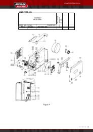
Figure 4.<br />
Turning the screw M10 clockwise increases the spring<br />
tension and you can increase the brake torque.<br />
Turning the screw M10 counterclockwise decreases the<br />
spring tension and you can decrease the brake torque.<br />
After finishing of adjustment, you should screw in the<br />
fastening cap again.<br />
Adjusting of Pressure Roll Force<br />
WARNING<br />
ELECTRIC SHOCK can kill.<br />
• Turn the input power OFF at the welding power<br />
source before installation or changing drive rolls<br />
and/or guides.<br />
• Do not touch electrically live parts.<br />
• When inching with the gun trigger, electrode and<br />
drive mechanism are "hot" to work and ground and<br />
could remain energized several seconds after the<br />
gun trigger is released.<br />
• Do not operate with covers, panels or guards<br />
removed or open.<br />
• Only qualified personnel should perform<br />
maintenance work.<br />
Pressure force is adjusted by turning the adjustment nut<br />
clockwise to increase force, counterclockwise to<br />
decrease force.<br />
Switch the Cold Inch / Gas Purge switch [2] (see Figure<br />
3.) in the position "Cold Inch" and keep in this position<br />
until the electrode wire leaves the contact tip of the<br />
welding torch.<br />
Set the wire feeding speed in the position of about<br />
10m/min by the Left Knob [2] (see Figure 1.).<br />
WARNING<br />
Take precaution to keep eyes and hands away from the<br />
end of the torch while feeding wire.<br />
WARNING<br />
Once the wire has finished feeding through the welding<br />
gun turn the machine “OFF“ before replacing to contact<br />
tip and gas diffuser.<br />
Changing Driving Rolls<br />
The machine is equipped with drive rolls for the wire of<br />
1.0 and 1.2mm (factory default). For others wire sizes,<br />
is available the proper drive rolls kit (see chapter<br />
Accessories for ordering the desired kit). Below is the<br />
drive rolls replacement procedure:<br />
• Switch off the machine.<br />
• Release the pressure roll lever [32].<br />
• Unscrew the fastening cap [33].<br />
• Open the protection cover [34].<br />
• Change the drive rolls [35] with the compatible ones<br />
corresponding to the used wire.<br />
WARNING<br />
For wires with the diameter greater than 1.6mm, the<br />
following parts are to be changed:<br />
• The guide tube of the feeding console [36] and<br />
[37].<br />
• The guide tube of the Euro socket [38].<br />
• Replace and tighten the protection cover [34] to the<br />
drive rolls.<br />
• Screw the protection cover by fastening screws [33].<br />
The pressure arm controls the amount of force the drive<br />
rolls exert on the wire. Proper adjustment of pressure<br />
arm gives the best welding performance. Set the<br />
pressure arm as follows:<br />
• Aluminum wires: between 1 and 3<br />
• Cored wires: between 3 and 4<br />
• Steel, Stainless wires: between 4 and 6<br />
WARNING<br />
If the roll pressure is too low the roll will slide on the wire.<br />
If the roll pressure is set too high the wire may be<br />
deformed, which will cause feeding problems in the<br />
welding gun. The pressure force should be set properly.<br />
Decrease the pressure force slowly until the wire just<br />
begins to slide on the drive roll and then increase the<br />
force slightly by turning of the adjustment nut by one<br />
turn.<br />
Inserting Electrode Wire into Welding<br />
Torch<br />
Connect the proper welding torch to the Euro socket, the<br />
rated parameters of the torch and of the welding source<br />
shall match.<br />
Figure 5.<br />
Making A Weld With Waveform<br />
Technology Power Sources<br />
9
WARNING<br />
The serviceability of a product or structure utilizing the<br />
welding programs is and must be the sole responsibility<br />
of the builder/user. Many variables beyond the control of<br />
The <strong>Lincoln</strong> <strong>Electric</strong> Company affect the results obtained<br />
in applying these programs. These variables include,<br />
but are not limited to welding procedure, plate chemistry<br />
and temperature, weldment design, fabrication methods<br />
and service requirements. The available range of a<br />
welding program may not be suitable for all applications,<br />
and the build/user is and must be solely responsible for<br />
welding program selection.<br />
The steps for operating the power source will vary<br />
depending upon the user interface of the welding<br />
system. The flexibility of the power source lets the user<br />
customize operation for the best performance.<br />
• First, consider the desired welding process and the<br />
part to be welded. Choose an electrode material,<br />
diameter, shielding gas and process (GMAW,<br />
SMAW, etc.)<br />
• Second, find the program in the welding software<br />
that best matches the desired welding process. The<br />
standard software shipped with the power source<br />
encompasses a wide range of common processes<br />
and will meet most needs. All adjustments are<br />
made on the user interface. Because of the<br />
different configuration options your system may not<br />
have all of the following adjustments.<br />
Regardless of availability, all controls are described<br />
below.<br />
SMAW (Stick) Welding<br />
SMAW is most often used for outdoor construction, pipe<br />
welding and general repairs. The wire feeder speed<br />
controls Amperage, Output Control and Arc Force.<br />
During SMAW welding, the wire feeder sets the weld<br />
parameters and the wire drive remains idle. The “Volts”-<br />
”Trim” control is used to turn the power Source Output<br />
ON or OFF (See Figure below)<br />
<br />
<br />
<br />
<br />
<br />
Figure 7. GTAW (TIG) Welding Display<br />
GMAW (MIG) Synergic Welding Display<br />
Synergic CV programs feature an ideal voltage best<br />
suited for most procedures. Use this voltage as a<br />
starting point and adjust if needed for personal<br />
preferences.<br />
<br />
<br />
<br />
<br />
<br />
<br />
Figure 8. GMAW (MIG) Synergic Welding Display<br />
Synergic CV Voltage Display<br />
When the voltage knob is rotated, the display will show<br />
an upper or lower bar indicating if the voltage is above or<br />
below the ideal voltage.<br />
• Preset voltage above ideal voltage<br />
(upper bar displayed)<br />
<br />
<br />
• Preset voltage at ideal voltage<br />
(no bar displayed)<br />
Figure 6. SMAW (Stick) Welding Display<br />
GTAW (TIG) Welding<br />
The SpeedTec is excellent for Touch Start TIG welding.<br />
The wire feeder speed controls Amperage. During<br />
SMAW welding, the wire feeder sets the weld<br />
parameters and the wire drive remains idle. The “Volts”-<br />
”Trim” control is used to turn the power Source Output<br />
ON or OFF (See Figure below)<br />
• Preset voltage below ideal voltage<br />
(lower bar displayed)<br />
MSP4 Operation<br />
Left Button:<br />
10
Electrode Gas<br />
Weld Mode<br />
Wire Size<br />
0.8 1.0 1.2 1.6<br />
Steel CO2 93 10 20 24<br />
Steel Ar(mix) 94 11 21 25<br />
Stainless Ar(mix) 61 31 41 ---<br />
Stainless Ar/He/CO2 63 33 43<br />
Alu 4043 Ar --- 148 71 ---<br />
Alu 5356 Ar --- 151 75 77<br />
FluxCore Gas Shld 155<br />
Effect Range<br />
Pinch Effect<br />
(-10.0 to +10.0)<br />
Effect Range<br />
Job1..Job8<br />
Right Button:<br />
Effect/Range<br />
Preflow Time<br />
0-25.0 seconds<br />
Run-in WFS<br />
Off, 1 to 12 m/min<br />
Start Procedure<br />
Effect/Range<br />
Spot Timer<br />
0 to 120.0 seconds<br />
Postflow Time<br />
0 to 25.0 seconds<br />
Burnback<br />
Crater Procedure<br />
Effect Range<br />
2-Step, 4-Step<br />
Arc Control<br />
Description<br />
Pinch controls the arc characteristics<br />
when short-arc welding.<br />
Memory<br />
Description<br />
Allows memorizing the selected weld<br />
mode.<br />
Start Options<br />
Description<br />
Adjusts the time that shielding gas<br />
flows after the trigger is pulled and prior<br />
to feeding.<br />
Run-in sets the wire feed speed from<br />
the time the trigger is pulled until an arc<br />
is established.<br />
The Start Procedure controls the WFS,<br />
Volts at a specified time at the<br />
beginning of the weld. During the start<br />
time, the machine will ramp up or down<br />
from the Start Procedure to the preset<br />
Welding Procedure.<br />
End options<br />
Description<br />
Adjust the time welding will continue even<br />
if the trigger is still pulled. This option has<br />
no effect in 4-Step Trigger Mode.<br />
Adjusts the time that shielding gas flows<br />
after the welding output turns off.<br />
The burnback time is the amount of time<br />
that the weld output continues after the<br />
wire stops feeding. It prevents the wire<br />
from sticking in the puddle and prepares<br />
the end of the wire for the next arc start.<br />
Crater Procedure controls the WFS and<br />
volts for a specified time at the end of the<br />
weld after the trigger is released. During<br />
the Crater time, the machine will ramp up<br />
or down from the Weld Procedure to the<br />
Crater Procedure.<br />
2/4 Step Mode<br />
Description<br />
Selects between 2-Step and 4-Step mode<br />
of weld.<br />
2- STEP 4- STEP- Trigger Operation<br />
The 2-Step - 4-Step switch changes the function of the<br />
gun trigger. 2-Step trigger operation switches the<br />
welding output ON-OFF in direct response to the trigger.<br />
4-Step trigger operation provides 'trigger interlock'<br />
capability and gives the ability to control the amount of<br />
time spent in the arc start and arc crater steps. Press<br />
the push button on the case front to toggle between 2-<br />
Step and 4-Step operation. The 2-Step, 4-Step trigger<br />
has no effect when welding with SMAW or CAG<br />
procedures.<br />
2-Step Trigger<br />
2-Step trigger operation is the most common. When the<br />
gun trigger is pulled, the welding system (power source<br />
and wire feeder) cycles through the arc starting<br />
sequence and into the main welding parameters. The<br />
welding system will continue to weld as long as the gun<br />
trigger is activated. Once the trigger is released, the<br />
welding system cycles through the arc ending steps.<br />
4-Step Trigger<br />
4-Step trigger operation gives the welder additional<br />
control in the welding sequence. 4-Step trigger allows<br />
the welder to choose the arc start, weld and arc end<br />
time. It may also be set-up to work as a trigger interlock.<br />
Example 1:<br />
2 Step Trigger: Simple operation<br />
The simplest trigger operation occurs with a 2 Step<br />
trigger and the Start, Crater and Burnback functions all<br />
set to OFF (See Figure Below). For this sequence:<br />
• PREFLOW: Shielding gas begins to flow<br />
immediately when the gun trigger is pulled.<br />
• RUN-IN: After preflow time expires, the power<br />
source regulates to the welding output and wire is<br />
advanced towards the work piece at the Run-In<br />
WFS. If an arc is not established within 1.5<br />
seconds, the wire feed speed will jump to the<br />
welding wire feed speed.<br />
• WELD: The power source output and the wire feed<br />
speed continue at the weld settings for as long as<br />
the trigger is pulled.<br />
• POSTFLOW: As soon as the trigger is released,<br />
the power source output and the wire feed speed<br />
are turned OFF. Shielding gas continues until the<br />
post flow timer expires.<br />
<br />
<br />
<br />
<br />
<br />
!<br />
<br />
<br />
<br />
<br />
<br />
<br />
<br />
<br />
<br />
<br />
"##<br />
"##<br />
$%"##<br />
<br />
<br />
&'<br />
Example 2:<br />
2 Step Trigger: Improved Arc Start and Arc End.<br />
Tailoring the arc start and arc end is a common method<br />
for reducing spatter and improving weld quality. This<br />
can be accomplished with the Start and Burnback<br />
functions set to a desired values and Crater set to OFF<br />
(See Figure Below). For this sequence:<br />
• PREFLOW: Shielding gas begins to flow<br />
immediately when the gun trigger is pulled.<br />
• RUN-IN: After preflow time expires, the power<br />
source regulates to the start output and wire is<br />
advanced towards the work piece at the Run-In<br />
WFS. If an arc is not established within 1.5<br />
seconds, the power source output and wire feed<br />
speed skips to the weld settings.<br />
• START & UPSLOPE: Once the wire touches the<br />
work and an arc is established, both the machine<br />
11
output and the wire feed speed ramp to the weld<br />
settings throughout the start time. The time period<br />
of ramping from the start settings to the weld<br />
settings is called UPSLOPE.<br />
• WELD: After upslope, the power source output and<br />
the wire feed speed continue at the weld settings.<br />
• BURNBACK: As soon as the trigger is released,<br />
the wire feed speed is turned OFF and the machine<br />
output continues for the burnback time.<br />
• POSTFLOW: Next, the machine output is turned<br />
OFF and shielding gas continues until the post flow<br />
timer expires.<br />
<br />
<br />
<br />
<br />
<br />
!<br />
<br />
<br />
<br />
<br />
<br />
<br />
<br />
<br />
<br />
<br />
<br />
"<br />
"##<br />
$%"<br />
<br />
<br />
&'<br />
<br />
$%<br />
Example 3:<br />
2 Step Trigger: Customized Arc Start, Crater and Arc<br />
End.<br />
Sometimes it is advantageous to set specific arc start,<br />
crater and arc ending parameters for the ideal weld.<br />
Many times when welding aluminum crater control is<br />
necessary to make a good weld. This is done by setting<br />
Start, Crater and Burnback functions to desired values<br />
(See Figure Below). For this sequence:<br />
• PREFLOW: Shielding gas begins to flow<br />
immediately when the gun trigger is pulled.<br />
• RUN-IN: After preflow time expires, the power<br />
source regulates to the start output and wire is<br />
advanced towards the work piece at the Run-In<br />
WFS. If an arc is not established within 1.5<br />
seconds, the power source output and wire feed<br />
speed skips to the weld settings.<br />
• START & UPSLOPE: Once the wire touches the<br />
work and an arc is established, both the machine<br />
output and the wire feed speed ramp to the weld<br />
settings throughout the start time. The time period<br />
of ramping from the start settings to the weld<br />
settings is called UPSLOPE.<br />
• WELD: After upslope, the power source output and<br />
the wire feed speed continue at the weld settings.<br />
• CRATER & DOWNSLOPE: As soon as the trigger<br />
is released, the wire feed speed and power source<br />
output ramp to the crater settings throughout the<br />
crater time. The time period of ramping from the<br />
weld settings to the crater settings is called<br />
DOWNSLOPE.<br />
• BURNBACK: After the crater time expires, the wire<br />
feed speed is turned OFF and the machine output<br />
continues for the burnback time.<br />
• POSTFLOW: Next, the machine output is turned<br />
OFF and shielding gas continues until the post flow<br />
timer expires.<br />
<br />
<br />
<br />
<br />
<br />
!<br />
! <br />
<br />
<br />
<br />
<br />
<br />
"<br />
<br />
<br />
"<br />
<br />
<br />
<br />
&'<br />
<br />
<br />
"<br />
"<br />
$%"<br />
<br />
<br />
$%<br />
Example 4:<br />
4 Step Trigger: Trigger Interlock<br />
The 4 step trigger can be configured as a trigger<br />
interlock. Trigger interlock adds to the welder’s comfort<br />
when making long welds by allowing the trigger to be<br />
released after an initial trigger pull. Welding stops when<br />
the trigger is pulled a second time and then released, or<br />
if the arc is interrupted (See Figure Below). For this<br />
sequence:<br />
• PREFLOW: Shielding gas begins to flow<br />
immediately when the gun trigger is pulled.<br />
• RUN-IN: After preflow time expires, the power<br />
source regulates to the welding output and wire is<br />
advanced towards the work piece at the Run-In<br />
WFS. If an arc is not established within 1.5<br />
seconds, the wire feed speed will jump to the<br />
welding wire feed speed.<br />
• WELD: The power source output and the wire feed<br />
speed continue at the weld settings. Welding<br />
continues when the trigger is pulled a second time.<br />
• POSTFLOW: As soon as the trigger is released for<br />
the second time, the power source output and the<br />
wire feed speed are turned OFF. Shielding gas<br />
flows until the post flow timer expires.<br />
<br />
<br />
<br />
<br />
<br />
!<br />
<br />
<br />
<br />
<br />
"<br />
<br />
<br />
"<br />
<br />
<br />
<br />
<br />
<br />
(<br />
"##<br />
"##<br />
$%"##<br />
<br />
&'<br />
Example 5:<br />
4 Step Trigger: Manual control of Start and Crater<br />
times with Burnback ON<br />
The 4 step trigger sequence gives the most flexibility<br />
<br />
<br />
12
when the Start, Crater and Burnback functions are<br />
active. This is a popular choice when welding aluminum<br />
because extra heat may be needed during Start and less<br />
heat desired during crater. With 4 step trigger, the<br />
welder chooses the amount of time to weld at the Start,<br />
Weld and Crater settings by using the gun trigger.<br />
Burnback reduces the occurrence of wire to sticking into<br />
the weld pool at the end of a weld and conditions the<br />
end of the wire for the next arc start ( See Figure Below).<br />
For this sequence:<br />
• PREFLOW: Shielding gas begins to flow<br />
immediately when the gun trigger is pulled.<br />
• RUN-IN: After preflow time expires, the power<br />
source regulates to the start output and wire is<br />
advanced towards the work piece at the run-in<br />
WFS. If an arc is not established within 1.5<br />
seconds, the power source output and wire feed<br />
speed skips to the weld settings.<br />
• START: The power source welds at the start WFS<br />
and voltage until the trigger is released.<br />
• UPSLOPE: During upslope, the power source<br />
output and the wire feed speed ramp to the weld<br />
settings throughout the start time. The time period<br />
of ramping from the start settings to the weld<br />
settings is called UPSLOPE.<br />
• WELD: After upslope, the power source output and<br />
the wire feed speed continue at the weld settings.<br />
• DOWNSLOPE: As soon as the trigger is released,<br />
the wire feed speed and power source output ramp<br />
to the crater settings throughout the crater time.<br />
The time period of ramping from the weld settings to<br />
the crater settings is called DOWNSLOPE.<br />
• CRATER: During CRATER, the power source<br />
continues to supply output at the crater WFS and<br />
voltage.<br />
• BURNBACK: When the trigger is released, the<br />
wire feed speed is turned OFF and the machine<br />
output continues for the burnback time.<br />
• POSTFLOW: Next, the machine output is turned<br />
OFF and shielding gas continues until the post flow<br />
timer expires.<br />
<br />
<br />
<br />
<br />
<br />
!<br />
<br />
<br />
<br />
<br />
"<br />
<br />
<br />
<br />
"<br />
<br />
<br />
<br />
<br />
<br />
(<br />
"<br />
"<br />
$%"<br />
! " <br />
&'<br />
<br />
<br />
<br />
$%<br />
SET-UP FEATURES MENU<br />
The Setup Menu gives access to the set-up<br />
configuration. Stored in the set-up configuration are<br />
user parameters that generally need to be set only at<br />
installation. The parameters are grouped as follows:<br />
• P.1 through P.99 Unsecured Parameters (always<br />
adjustable).<br />
• P.101 through P.199 Diagnostic Parameters<br />
(always read only).<br />
• P.501 through P.599 Secured Parameters<br />
(accessible only though a p.c. or palm application).<br />
To access the set-up menu, press the right and left<br />
buttons of the MSP4 panel simultaneously. Note that<br />
the set-up menu cannot be accessed if the system is<br />
welding, or if there is a fault (The status LED is not solid<br />
green). Change the value of the blinking parameter by<br />
rotating the SET knob.<br />
After changing a parameter it is necessary to press the<br />
right hand button to save the new setting. Pressing the<br />
left button will cancel the change. To exit the set-up<br />
menu at any time, press the right and left buttons of the<br />
MSP4 panel simultaneously. Alternately, 1 minute of<br />
inactivity will also exit the setup menu.<br />
Unsecured Parameters.<br />
P.0 Press the left button to exit the set-up menu.<br />
P.1 WFS units<br />
• Metric = m/min wire feed speed units<br />
• English = in/min wire feed speed units (default)<br />
P.2 Arc Display Mode<br />
• Amps = The left display shows Amperage while<br />
welding. (default)<br />
• WFS = The left display shows Wire Feed Speed<br />
while welding.<br />
P.4 Trigger Memory Recall<br />
• Enable = Selecting memories 2 through 6 with quick<br />
trigger pulls is enabled when the optional dual<br />
procedure/memory panel is installed. To recall a<br />
memory with the gun trigger, quickly pull and<br />
release the trigger the number of times that<br />
correspond to the memory number. For example, to<br />
recall memory 3, quickly pull and release the trigger<br />
3 times. Trigger memory recall can only be<br />
performed when the system is not welding.<br />
• Disable = Memory selection is performed only by<br />
the buttons on the optional dual procedure/memory<br />
panel (default).<br />
P.5 Trigger Procedure Change<br />
• Quick Trigger = Allows switching between<br />
Procedure A and procedure B while welding. The<br />
optional dual procedure/memory panel is required.<br />
To operate:<br />
Select procedure “GUN” on the memory panel.<br />
Start the weld by pulling the gun trigger. The<br />
system will weld with procedure A settings.<br />
While welding, quickly release and then pull the<br />
gun trigger. The system will switch to<br />
procedure B settings.<br />
<br />
Release the trigger to stop welding. When the<br />
next weld is made, the system will start again<br />
with procedure A.<br />
• Integral TrigProc = Use Integral Trigger + Procedure<br />
Switch when using a <strong>Lincoln</strong> Dual Schedule gun.<br />
When in 2-step, the system operates identical to the<br />
External Switch selection. To operate in 4-step:<br />
<br />
<br />
<br />
Select procedure “GUN” on the memory panel.<br />
Start the weld by pulling the gun trigger. The<br />
system will weld with procedure A settings.<br />
While welding, quickly release and then pull the<br />
gun trigger. The system will switch to<br />
procedure B settings.<br />
13
Release the trigger to stop welding. When the<br />
next weld is made, the system will start again<br />
with procedure A.<br />
• External Switch = Dual Procedure selection may<br />
only be performed by the memory panel button or a<br />
dual procedure gun (default).<br />
P.6 Push Pull Gun, Stall Factor Adjustment<br />
The stall factor controls the stall torque of the push<br />
motor when using a push-pull gun. The wire feeder is<br />
factory set to not stall unless there is a large resistance<br />
to feeding wire. The stall factor can be reduced to stall<br />
more easily and possibly prevent bird nesting. However,<br />
low stall factors can cause motor stalling while welding<br />
which results in the wire burning back to the tip. If you<br />
are experiencing bird nests, check for other feeding<br />
problems before adjusting the stall factor. Default value<br />
for the stall factor is 75, with a range of 5 - 100. To<br />
change the stall factor:<br />
• Use the VOLTS/TRIM knob to adjust the stall factor.<br />
Increasing the stall factor raises the motor torque<br />
and decreasing the stall factor lowers the motor<br />
torque. Do not increase the stall factor more than<br />
necessary. A high stall factor may increase the<br />
occurrence of bird nesting and a low stall factor may<br />
cause the wire to burn back to the tip.<br />
• Press the right hand button to save the new setting.<br />
P.7 Push Pull Gun, Gun Offset Adjustment<br />
The pushpull gun offset calibration adjusts the wire feed<br />
speed calibration of the pull motor. The procedure<br />
should only be performed when other possible<br />
corrections do not solve the push-pull feeding problems.<br />
A rpm meter is required to perform the pull gun motor<br />
offset calibration. To perform the calibration procedure:<br />
• Release the pressure arm on both the pull and push<br />
wire drives.<br />
• Set the wire feed speed to 200 rpm.<br />
• Remove wire from the pull wire drive.<br />
• Hold the rpm meter to the drive roll in the pull gun.<br />
• Pull the trigger on the push-pull gun.<br />
• Measure the rpm of the pull motor. The rpm should<br />
be between 115 and 125 rpm. If necessary,<br />
decrease the calibration setting to slow the pull<br />
motor, or increase the calibration setting to speed<br />
up the motor. The calibration range is -30 to +30,<br />
with 0 as the default value.<br />
• Press the right hand button to save the new setting.<br />
P.8 TIG Gas Control (Two Settings)<br />
• 1. "Valve (manual)", the internal solenoid will not<br />
actuate while TIG welding, gas flow is manually<br />
controlled by an external valve.<br />
• 2. "Solenoid (auto)", the internal gas solenoid will<br />
turn on and off automatically while TIG welding as<br />
follows:<br />
Preflow time will not be accessible from the<br />
MSP4.<br />
Postflow time will be available in the MSP4<br />
"End Options" and have a range of OFF to 10.0<br />
seconds.<br />
The postflow time value is maintained when<br />
switching between MIG and TIG modes.<br />
When machine output on/off is controlled via<br />
the right encoder, gas flow will not start until the<br />
tungsten touches, the work piece, gas flow will<br />
stop after the postflow time when the arc is<br />
broken.<br />
When machine output on/off is controlled via an<br />
arc start switch or foot Amptrol, gas will begin<br />
flowing when the output is turned on and stop<br />
flowing after the postflow period after the output<br />
is turned off.<br />
P.9 Crater Delay<br />
Use the crater delay to skip the Crater sequence when<br />
making short tack welds. If the trigger is released before<br />
the Crater Delay Timer ends, then the Crater sequence<br />
is skipped. If the trigger is released afterwards, the<br />
Crater sequence functions normally.<br />
• Values = OFF to 10.0 seconds (OFF is default).<br />
P.11 Set Timers<br />
This menu is used to adjust timer values for Upslope,<br />
Downslope and Restrike. Press the right button to enter<br />
the Set Timer menu. Rotate the knob to select the timer<br />
to adjust and then press the right button. Adjust the<br />
value of the timer by rotating the knob. Press the left<br />
MSP4 button to set the value and exit. Continue to<br />
adjust other timers as necessary, and then press the left<br />
button to exit the Set Timer menu.<br />
P.12 Travel Options<br />
This menu is used to change the travel options for a<br />
travel carriage, including starting and ending functions.<br />
The right MSP4 button to enter the Travel Options menu<br />
and rotate the encoder to select either starting or ending<br />
options. Press the right MSP4 button to select the<br />
option. Press the left MSP4 button to set the value and<br />
exit. Rotate the encoder to select other options, or press<br />
the left MSP4 button to exit the menu.<br />
P.13 Adjust Arc Force<br />
Use this menu to adjust Arc Force values for Start, Weld<br />
and Crater. Press the right MSP4 button to enter the<br />
menu and rotate the knob to choose either Start, Weld or<br />
Crater. Press the right MSP4 button and then rotate the<br />
knob to the desired value. Press the left MSP4 button to<br />
set the value and exit. Continue to adjust Arc Force for<br />
other states, and then press the left MSP4 button to exit<br />
the menu.<br />
P.14 Reset Consumable Weight<br />
This parameter only appears with systems using<br />
Production Monitoring. Use this parameter to reset the<br />
initial weight of the consumable package.<br />
P.16 Push-Pull Gun Knob<br />
• Gun Pot Enabled = The wire feed speed is always<br />
controlled by the potentiometer on the push-pull gun<br />
(default).<br />
• Gun Pot Disabled = The wire feed speed is always<br />
controlled by the left display knob on the feeder.<br />
• Gun Pot Proc A = When in procedure A, the wire<br />
feed speed is set by the push-pull gun<br />
potentiometer. When in procedure B, the wire feed<br />
speed is set by the left display knob on the feeder.<br />
P.20 Trim In Volts<br />
P.25 Joystick Configuration<br />
The new analog and digital gun controls have a joystick<br />
to allow the user to change various weld settings at the<br />
gun rather than having to go to the user interface. P.25<br />
can be used to change the behavior of the joystick. In all<br />
configurations, the up and down joystick positions will<br />
adjust the wire feed speed, while welding and while not<br />
welding. P.25 is used to reconfigure the behavior of the<br />
left and right joystick positions.<br />
14
• When P.25 is set to “Trim/Volts/etc.”, the left and<br />
right joystick positions will adjust Arc Length Trim,<br />
Arc Voltage, Power or STT Background Current<br />
based on the selected weld mode. For example,<br />
when a non-synergic STT weld mode is selected,<br />
the left and right joystick positions will adjust<br />
Background Current. When a Power mode is<br />
selected, the left and right joystick positions will<br />
adjust the Power (kW).<br />
• When P.25 is set to “Memory+Trim/etc.”, the left<br />
and right joystick positions will select a user memory<br />
while not welding and adjust<br />
Trim/Voltage/Power/STT Background Current while<br />
welding.<br />
• When P.25 is set to “Procedure A/B”, the left and<br />
right joystick positions will be used to select<br />
procedure A and B, while welding and while not<br />
welding. The left joystick position selects procedure<br />
A, the right joystick position selects procedure B.<br />
Diagnostic Parameters<br />
P.80 Sense from Studs<br />
Use this parameter for diagnostic purposes only. When<br />
power is cycled, P.80 is automatically reset to False.<br />
• False = Sensing for the electrode (67) and work (21)<br />
is determined by the DIP switches of the system.<br />
• True = Sensing for the electrode (67) and work (21)<br />
is measured at the studs of the power source and<br />
the DIP switch settings are overridden.<br />
P.99 Show Test Modes<br />
Many weld tables include special modes for testing and<br />
servicing the welding system. Set this parameter to YES<br />
to show all test modes. When the power source is<br />
turned off, the Show Test Modes parameter<br />
automatically reverts back to "NO".<br />
P.100 View Diagnostics<br />
Diagnostics are only used for servicing the Power Wave<br />
system.<br />
• Yes = Shows P.101 through P.500 in the SETUP<br />
menu.<br />
• No = Only P.0 through P.100 are shown in the<br />
SETUP menu.<br />
P.101 Event Logs<br />
Press the right MSP4 button to view the Event Logs.<br />
Rotate the encoder to select the object to read and then<br />
press the right MSP4 button. Various software<br />
information will appear about key system events. Press<br />
the left MSP4 button to exit.<br />
P.102 Fatal Logs<br />
Press the right MSP4 button to view the Fatal Logs.<br />
Rotate the encoder to select the module to read and<br />
then press the right MSP4 button. Various software<br />
information will appear about critical module actions.<br />
Press the left MSP4 button to exit.<br />
P.103 Software Version<br />
Press the right MSP4 button to view the software loaded<br />
into each module (p.c. board). Rotate the encoder to<br />
select the module to read and then press the right MSP4<br />
button. The panel will display the main software version<br />
loaded into the module. Press the left MSP4 button to<br />
exit.<br />
P.104 Hardware Version<br />
Press the right MSP4 button to view the hardware<br />
version of each module (p.c. board). Rotate the encoder<br />
to select the module to read and then press the right<br />
MSP4 button. The panel will display the main hardware<br />
version loaded into the module. Press the left MSP4<br />
button to exit.<br />
P.105 Welding Software<br />
Press the right MSP4 button to view the welding<br />
software version inside the power source. Press the left<br />
MSP4 button to exit.<br />
P.106 Ethernet IP Address<br />
Press the right MSP4 button to view the IP address of<br />
the Ethernet board. If no Ethernet Board is installed, the<br />
display shows "No Enet Found". Press the left MSP4<br />
button to exit.<br />
P.107 Power Source<br />
Press the right MSP4 button to view the type of power<br />
source connected to the control box. Press the left<br />
MSP4 button to exit.<br />
Maintenance<br />
WARNING<br />
For any maintenance or repair operations it is<br />
recommended to contact the nearest technical service<br />
center or <strong>Lincoln</strong> <strong>Electric</strong>. Maintenance or repairs<br />
performed by unauthorized service centers or personnel<br />
will null and void the manufacturers warranty.<br />
The frequency of the maintenance operations may vary<br />
in accordance with the working environment where the<br />
machine is placed.<br />
Any noticeable damage should be reported immediately.<br />
Routine maintenance<br />
• Check condition of insulation and connections of the<br />
work cables and input power supply cable.<br />
• Remove the spatters from the welding gun nozzle.<br />
Spatters could interfere with the shielding gas flow<br />
to the arc.<br />
• Check the welding gun condition: replace it, if<br />
necessary.<br />
• Check condition and operation of the cooling fan.<br />
Keep clean its airflow slots.<br />
Periodic maintenance<br />
Perform the routine maintenance and, in addition:<br />
• Keep clean the machine. Using a dry ( and low<br />
pressure) airflow, remove the dust from the external<br />
case and from inside of the cabinet.<br />
• Check condition of all connections and change if<br />
necessary.<br />
• Check and tighten all screws.<br />
WARNING<br />
Mains supply network must be disconnected from the<br />
machine before each maintenance and service. After<br />
each repair, perform proper tests to ensure safety.<br />
15
Electromagnetic Compatibility (EMC)<br />
11/04<br />
This machine has been designed in accordance with all relevant directives and standards. However, it may still generate<br />
electromagnetic disturbances that can affect other systems like telecommunications (telephone, radio, and television) or<br />
other safety systems. These disturbances can cause safety problems in the affected systems. Read and understand<br />
this section to eliminate or reduce the amount of electromagnetic disturbance generated by this machine.<br />
This machine has been designed to operate in an industrial area. To operate in a domestic area it is<br />
necessary to observe particular precautions to eliminate possible electromagnetic disturbances. The<br />
operator must install and operate this equipment as described in this manual. If any electromagnetic<br />
disturbances are detected the operator must put in place corrective actions to eliminate these disturbances<br />
with, if necessary, assistance from <strong>Lincoln</strong> <strong>Electric</strong>.<br />
Before installing the machine, the operator must check the work area for any devices that may malfunction because of<br />
electromagnetic disturbances. Consider the following.<br />
• Input and output cables, control cables, and telephone cables that are in or adjacent to the work area and the<br />
machine.<br />
• Radio and/or television transmitters and receivers. Computers or computer controlled equipment.<br />
• Safety and control equipment for industrial processes. Equipment for calibration and measurement.<br />
• Personal medical devices like pacemakers and hearing aids.<br />
• Check the electromagnetic immunity for equipment operating in or near the work area. The operator must be sure<br />
that all equipment in the area is compatible. This may require additional protection measures.<br />
• The dimensions of the work area to consider will depend on the construction of the area and other activities that are<br />
taking place.<br />
Consider the following guidelines to reduce electromagnetic emissions from the machine.<br />
• Connect the machine to the input supply according to this manual. If disturbances occur if may be necessary to take<br />
additional precautions such as filtering the input supply.<br />
• The output cables should be kept as short as possible and should be positioned together. If possible connect the<br />
work piece to ground in order to reduce the electromagnetic emissions. The operator must check that connecting<br />
the work piece to ground does not cause problems or unsafe operating conditions for personnel and equipment.<br />
• Shielding of cables in the work area can reduce electromagnetic emissions. This may be necessary for special<br />
applications.<br />
Technical Specifications<br />
INPUT VOLTAGE<br />
WIRE <strong>FEED</strong> SPEED<br />
34-44 Vdc 1.0-20 m/min<br />
RATED OUTPUT AT 40°C<br />
Duty Cycle<br />
Output Current<br />
(based on a 10 min. period)<br />
100%<br />
60%<br />
Welding Current Range<br />
5-500 A<br />
Solid wires<br />
0.6 to 1.6<br />
Height<br />
440 mm<br />
Operating Temperature<br />
–10°C to +40°C<br />
OUTPUT RANGE<br />
WIRE SIZES (mm)<br />
Cored wires<br />
1.0 to 2.0<br />
PHYSICAL DIMENSIONS<br />
Width<br />
Length<br />
270 mm<br />
636 mm<br />
385 A<br />
500 A<br />
Maximum Open Circuit Voltage<br />
113 Vdc or Vac peak<br />
Aluminium wires<br />
1.0 to 1.6<br />
Storage Temperature<br />
-25°C to +55°C<br />
Weight<br />
17 Kg<br />
16
Bezpieczestwo Uytkowania<br />
11/04<br />
OSTRZE ENIE<br />
Urzdzenie to moe by uywane tylko przez wykwalifikowany personel. Naley by pewnym, e instalacja, obsługa, przegldy i<br />
naprawy s przeprowadzane tylko przez osoby wykwalifikowane. Instalacji i eksploatacji tego urzdzenia mona dokona tylko po<br />
dokładnym zapoznaniu si z t instrukcj obsługi. Nieprzestrzeganie zalece zawartych w tej instrukcji moe narazi uytkownika na<br />
powane obraenie ciała, mier lub uszkodzenie samego urzdzenia. <strong>Lincoln</strong> <strong>Electric</strong> nie ponosi odpowiedzialnoci za uszkodzenia<br />
spowodowane niewłaciw instalacj, niewłaciw konserwacj lub nienormaln obsług.<br />
OSTRZE ENIE: Symbol ten wskazuje, e bezwzgldnie musz by przestrzegane instrukcje dla uniknicia<br />
powanego obraenia ciała, mierci lub uszkodzenia samego urzdzenia. Chro siebie i innych przed moliwym<br />
powanym obraeniem ciała lub mierci.<br />
CZYTAJ ZE ZROZUMIENIEM INSTRUKCJ: Przed rozpoczciem uytkowania tego urzdzenia przeczytaj<br />
niniejsz instrukcj ze zrozumieniem. Łuk spawalniczy moe by niebezpieczny. Nieprzestrzeganie instrukcji tutaj<br />
zawartych moe spowodowa powane obraenia ciała, mier lub uszkodzenie samego urzdzenia.<br />
PORA ENIE ELEKTRYCZNE MO E ZABI: Urzdzenie spawalnicze wytwarza wysokie napicie. Nie dotyka<br />
elektrody, uchwytu spawalniczego lub podłczonego materiału spawanego, gdy urzdzenie jest załczone do<br />
sieci. Odizolowa siebie od elektrody, uchwytu spawalniczego i podłczonego materiału spawanego.<br />
URZDZENIE ZASILANE ELEKTRYCZNIE: Przed przystpieniem do jakichkolwiek prac przy tym urzdzeniu<br />
odłczy jego zasilanie sieciowe. Urzdzenie to powinno by zainstalowane i uziemione zgodnie z zaleceniami<br />
producenta i obowizujcymi przepisami.<br />
URZDZENIE ZASILANE ELEKTRYCZNIE: Regularnie sprawdza kable zasilajcy i spawalnicze z uchwytem<br />
spawalniczym i zaciskiem uziemiajcym. Jeeli zostanie zauwaone jakiekolwiek uszkodzenie izolacji,<br />
natychmiast wymieni kabel. Dla uniknicia ryzyka przypadkowego zapłonu nie kła uchwytu spawalniczego<br />
bezporednio na stół spawalniczy lub na inn powierzchni majc kontakt z zaciskiem uziemiajcym.<br />
POLE ELEKTROMAGNETYCZNE MO E BY NIEBEZPIECZNE: Prd elektryczny płyncy przez jakikolwiek<br />
przewodnik wytwarza wokół niego pole elektromagnetyczne. Pole elektromagnetyczne moe zakłóca prac<br />
rozruszników serca i spawacze z wszczepionym rozrusznikiem serca przed podjciem pracy z tym urzdzeniem<br />
powinni skonsultowa si ze swoim lekarzem.<br />
ZGODNO Z CE: Urzdzenie to spełnia zalecenia Europejskiego Komitetu CE.<br />
OPARY I GAZY MOG BY NIEBEZPIECZNE: W procesie spawania mog powstawa opary i gazy<br />
niebezpieczne dla zdrowia. Unika wdychania tych oparów i gazów. Dla uniknicia takiego ryzyka musi by<br />
zastosowana odpowiednia wentylacja lub wycig usuwajcy opary i gazy ze strefy oddychania.<br />
PROMIENIE ŁUKU MOG POPARZY: Stosowa mask ochronn z odpowiednim filtrem i osłony dla<br />
zabezpieczenia oczu przed promieniami łuku podczas spawania lub jego nadzoru. Dla ochrony skóry stosowa<br />
odpowiedni odzie wykonan z wytrzymałego i niepalnego materiału. Chroni personel postronny, znajdujcy si<br />
w pobliu, przy pomocy odpowiednich, niepalnych ekranów lub ostrzega ich przed patrzeniem na łuk lub<br />
wystawianiem si na jego oddziaływanie.<br />
ISKRY MOG SPOWODOWA PO AR LUB WYBUCH: Usuwa wszelkie zagroenie poarem z obszaru<br />
prowadzenia prac spawalniczych. W pogotowiu powinny by odpowiednie rodki ganicze. Iskry i rozgrzany<br />
materiał pochodzce od procesu spawania łatwo przenikaj przez małe szczeliny i otwory do przyległego obszaru.<br />
Nie spawa adnych pojemników, bbnów, zbiorników lub materiału dopóki nie zostan przedsiwzite<br />
odpowiednie kroki zabezpieczajce przed pojawieniem si łatwopalnych lub toksycznych gazów. Nigdy nie<br />
uywa tego urzdzenia w obecnoci łatwopalnych gazów, oparów lub łatwopalnych cieczy.<br />
SPAWANY MATERIAŁ MO E POPARZY: Proces spawania wytwarza du ilo ciepła. Rozgrzane<br />
powierzchnie i materiał w polu pracy mog spowodowa powane poparzenia. Stosowa rkawice i szczypce, gdy<br />
dotykamy lub przemieszczamy spawany materiał w polu pracy.<br />
ZNAK BEZPIECZESTWA: Urzdzenie to jest przystosowane do zasilania sieciowego, do prac spa-walniczych<br />
prowadzonych w rodowisku o podwyszonym ryzyku poraenia elektrycznego.<br />
BUTLA MO E WYBUCHN JELI JEST USZKODZONA: Stosowa tylko butle atestowane z gazem<br />
odpowiedniego rodzaju do stosowanego procesu i poprawnie działajcymi regulatorami cinienia, przeznaczonymi<br />
dla stosowanego gazu i cinienia. Zawsze utrzymywa butl w pionowym połoeniu, zabezpieczajc j łacuchem<br />
przed wywróceniem si. Nie przemieszcza i nie transportowa butli z gazem ze zdjtym kołpakiem<br />
zabezpieczajcym. Nigdy nie dotyka elektrody, uchwytu spawalniczego, zacisku uziemiajcego lub<br />
17
jakiegokolwiek elementu obwodu przewodzcego prd do butli z gazem. Butle z gazem musz by umieszczane z<br />
dala od miejsca gdzie mogłyby ulec uszkodzeniu lub gdzie byłyby naraone na działanie iskier lub rozgrzanej<br />
powierzchni.<br />
Instrukcja Instalacji i Eksploatacji<br />
Przed instalacj i rozpoczciem uytkowania tego urzdzenia<br />
naley przeczyta cały ten rozdział.<br />
Warunki Eksploatacji<br />
Urzdzenie to moe pracowa w cikich warunkach.<br />
Jednake wanym jest zastosowanie prostych rodków<br />
zapobiegawczych, które zapewni dług ywotno i<br />
niezawodn prac, midzy innymi:<br />
• Nie umieszcza i nie uytkowa tego urzdzenia na<br />
powierzchni o pochyłoci wikszej ni 15°.<br />
• Nie uywa tego urzdzenia do rozmraania rur.<br />
• Urzdzenie to musi by umieszczone w miejscu gdzie<br />
wystpuje swobodna cyrkulacja czystego powietrza bez<br />
ogranicze przepływu powietrza do i od wentylatora. Gdy<br />
urzdzenie jest załczone do sieci, niczym go nie<br />
przykrywa np. papierem lub cierk.<br />
• Ograniczy do minimum brud i kurz, które mog<br />
przedosta si do urzdzenia.<br />
• Urzdzenie to posiada stopie ochrony obudowy IP23.<br />
Utrzymywa je suchym, o ile to moliwe, i nie umieszcza<br />
na mokrym podłou lub w kałuy.<br />
• Urzdzenie to powinno by umieszczone z dala od<br />
urzdze sterowanych drog radiow. Jego normalna<br />
praca moe niekorzystnie wpłyn na ulokowane w<br />
pobliu urzdzenia sterowane radiowo, co moe<br />
doprowadzi do obraenia ciała lub uszkodzenia<br />
urzdzenia. Przeczytaj rozdział o kompatybilnoci<br />
elektromagnetycznej zawarty w tej instrukcji.<br />
• Nie uywa tego urzdzenia w temperaturach otoczenia<br />
wyszych ni 40°C.<br />
Cykl Pracy i Przegrzanie<br />
Cykl pracy urzdzenia jest procentowym podziałem 10<br />
minutowego cyklu, przez który mona spawa ze<br />
znamionowym prdem spawania.<br />
Przykład: 60% cykl pracy:<br />
Dopuszczalna warto napicia zasilania ródła prdu podana<br />
jest na tabliczce znamionowej podajnika drutu. Skontrolowa<br />
połczenia przewodów uziemiajcych od ródła do sieci<br />
zasilajcej.<br />
Podłczenie gazu<br />
Na butli z gazem musi by zainstalowany odpowiedni reduktor<br />
gazu. Po starannym zainstalowaniu reduktora na butli z gazem<br />
naley podłczy w gazowy od reduktora przepływu do<br />
wejcia zasilania gazu w urzdzeniu - punkt [18] na poniszych<br />
rysunkach. Podajnik umoliwia stosowanie wszystkich gazów i<br />
mieszanek osłonowych wliczajc w to dwutlenek wgla, argon i<br />
hel o maksymalnym cinieniu 5,0 bar.<br />
Podłczenie uchwytu spawalniczego<br />
Punkt [10] na poniszych rysunkach.<br />
Opis elementów sterowania i obsługi<br />
Rysunek 1.<br />
6 minut spawania 4 minuty przerwy<br />
Nadmierne wydłuenie cyklu pracy urzdzenia moe<br />
spowodowa uaktywnienie si układu zabezpieczenia<br />
termicznego.<br />
Urzdzenie jest zabezpieczone przed nadmiernym nagrzaniem<br />
przez czujnik termiczny. Kiedy urzdzenie jest przegrzane,<br />
wieci si wskanik zabezpieczenia termicznego na panelu<br />
przednim podajnika drutu elektrodowego, a wyjcie zostaje<br />
odłczone. Kiedy urzdzenie schłodzi si do odpowiedniej<br />
temperatury, lampka zabezpieczenia termicznego ganie i jest<br />
moliwa normalna praca. Uwaga: dla bezpieczestwa,<br />
urzdzenie nie załcza si po zadziałaniu czujnika termicznego<br />
o ile nie został zwolniony przycisk uchwytu spawalniczego.<br />
1. Lewy Wywietlacz: Pokazuje Prdko Podawania Drutu<br />
lub Warto Prdu Spawania.<br />
2. Lewe Pokrtło: Ustawia wartoci w lewym wywietlaczu.<br />
3. Wywietlacz MSP4: Pokazuje szczegółowe informacje na<br />
temat parametrów spawania i diagnostyczne.<br />
4. Pokrto Ustawie Parametrów: Zmienia parametry<br />
wywietlane na wywietlaczu MSP4.<br />
5. Lewy Przycisk: Zmienia stan wywietlacza MSP4 na<br />
wywietlanie Tryb Spawania lub Kontrola Łuku.<br />
6.<br />
7. Gniazdo 12-pinowe: Gniazdo do zdalnego sterowania i<br />
uchwytu typu Push-Pull.<br />
8. Gniazdo Szybkozłczki: Ciepła woda z uchwytu.<br />
Minuty<br />
lub zmniejszy<br />
cykl pracy<br />
Podłczenie napicia zasilania<br />
Sprawdzi napicie zasilania, ilo faz i czstotliwo ródła<br />
prdu przed podłczeniem do niego podajnika drutu.<br />
9. Gniazdo Szybkozłczki: Zimna woda do uchwytu.<br />
10. Gniazdo uchwytu Spawalniczego EURO.<br />
11. Prawy Przycisk: Zmienia stan wywietlacza MSP4 aby<br />
wywietli opcje startu lub koca spawania.<br />
18
12. Wskanik Trybu Ustawianie: wieci si kiedy podajnik jest<br />
w trybie ustawiania parametrów.<br />
13. Wskanik Przekroczenia Temperatury: wieci si, gdy<br />
maksymalna temperatura pracy urzdzenia zostanie<br />
przekroczona.<br />
14. Prawe Pokrtło: Ustawia wartoci na prawym<br />
wywietlaczu.<br />
15. Prawy Wywietlacz: Pokazuje warto napicia lub<br />
warto trymu.<br />
1. Podajnik Drutu: 4-rolkowy podajnik drutu z systemem<br />
rolek o rednicy 37mm.<br />
2. Test Drutu / Test Gazu: Przycisk ten pozwala na<br />
włczenie podawania drutu (Test Drutu) i podawania gazu<br />
(Test Gazu) bez podawnia napicia na wyjcie urzdzenia.<br />
3. Wspornik Szpuli Drutu: Szpule drutu o ciarze<br />
maksymalnym 15kg. Akceptuje plastikowe, stalowe szpule<br />
na trzpie o rednicy 51mm.<br />
UWAGA<br />
Podajnik drutu Linc Feed moe by uywany wyłcznie z<br />
zamknit klap.<br />
Zakładanie Drutu Elektrodowego<br />
Otworzy pokryw boczn półautomatu.<br />
Odkrci z tulei hamulcowej zakrtk mocujc szpul.<br />
Nałoy szpul z drutem na tulej tak, eby szpula obracała si<br />
zgodnie z ruchem wskazówek zegara gdy drut jest<br />
wprowadzany do podajnika.<br />
Upewni si, czy bolec naprowadzajcy szpuli wszedł do<br />
otworu naprowadzajacego tulei.<br />
Zakrci zakrtk tulei hamulcowej.<br />
Do podajnika drutu zamontowa rolki napdowe odpowiednie<br />
do rednicy drutu elektrodowego.<br />
Uwolni koniec drutu ze szpuli i obci go, upewniajc si, czy<br />
nie ma zadzioru.<br />
Rysunek 2.<br />
1. Gniazda szybkozłczki gazowej: Podłczenie przewodu<br />
gazowego.<br />
2. Gniazdo 5-pinowe: Podłczenie ArcLink do ródła mocy.<br />
3. Gniazdo prdowe: Podłczeie przewodu prdowego mocy<br />
4. i 5. Gniazda szybkozłczek: Jeeli jest uywany uchwyt<br />
spawalniczy chłodzony wod słu do podłczenia<br />
przewodów dostarczajcych płyn chłodzacy do uchwytu<br />
spawalniczego.<br />
UWAGA<br />
Ostry koniec drutu moe grozi skaleczeniem.<br />
Obróci szpul z drutem zgodnie z ruchem wskazówek zegara i<br />
wprowadzi drut do podajnika drutu przepychajc go a do<br />
gniazda EURO.<br />
Odpowiednio wyregulowa sił docisku rolek podajnika drutu.<br />
Regulacja Momentu Hamowania Tulei<br />
Dla uniknicia rozwinicia si drutu elektrodowego po<br />
zakoczeniu spawania, tuleja jest wyposaona w układ<br />
hamujcy.<br />
Regulacji dokonuje si za pomoc ruby M10 znajdujcej si<br />
wewntrz korpusu tulei, po odkrceniu zakrtki mocujacej<br />
tulej.<br />
Rysunek 4.<br />
20. Zakrtka mocujca szpul.<br />
21. ruba regulujca M10.<br />
22. Spryna dociskowa.<br />
Krcc rub M10 zgodnie z ruchem wskazówek zegara<br />
zwiksza si docisk spryny co powoduje zwikszenie<br />
momentu hamowania.<br />
Rysunek 3.<br />
Krcc rub M10 w kierunku przeciwnym do ruchu wskazówek<br />
zegara zmniejsza si docisk spryny co powoduje<br />
zmniejszenie momentu hamowania.<br />
Po zakoczeniu regulacji zakrtk mocujc tulej naley<br />
19
ponownie zakrci.<br />
Regulacja Siły Ramienia Dociskowego<br />
Siła docisku jest ustawiana przez dokrcanie pokrtła<br />
regulacyjnego; pokrcanie go w kierunku zgodnym z ruchem<br />
wskazówek zegara - zwiksza sił docisku, pokrcanie go w<br />
kierunku przeciwnym - zmniejsza sił docisku.<br />
UWAGA<br />
Przy zbyt małej sile docisku drut lizga si po rolce czynnej.<br />
Zbyt dua siła docisku deformuje drut i powoduje problemy z<br />
jego podawaniem. Sił docisku naley ustawi prawidłowo.<br />
Powoli zmniejsza sił docisku do momentu, a drut zacznie si<br />
lizga po rolce czynnej, a nastpnie lekko zwikszy sił<br />
docisku przez obrót pokrtła regulacyjnego o jeden obrót.<br />
Wprowadzanie Drutu Elektrodowego do<br />
Uchwytu Spawalniczego<br />
Zamocowo odpowiedni uchwyt spawalniczy do gniazda EURO<br />
dopasowujc parametry znaminowe tego uchwytu do<br />
parametrów znamionowych ródła.<br />
Odkrci dysz gazow z kocówki uchwytu spawalniczego.<br />
Pokrtłem regulacji prdkoci podawania drutu [2] ustawi<br />
prdko na warto około 10m/min.<br />
Przełcznik test drutu / test gazu [15] przełczy w połoenie<br />
test drutu i trzyma go w tym połoeniu do momentu wyjcia<br />
drutu elektrodowego z kocówki uchwytu.<br />
UWAGA<br />
Zachowa rodki ostronoci trzymajc oczy i rce daleko od<br />
koca uchwytu podczas wyjcia drutu elektrodowego z<br />
uchwytu.<br />
UWAGA<br />
Zaraz po wyjciu drutu z kocówki uchwytu, zasilanie podajnika<br />
powinno zosta wyłczone a dysza gazowa ponownie<br />
zainstalowana.<br />
Wymiana rolek napdowych<br />
Podajnik fabrycznie jest wyposaone w rolki napdowe do drutu<br />
elektrodowego o rednicy 1,0mm i 1,2mm. Jeeli zachodzi<br />
konieczno spawania drutem elektrodowym o innej rednicy<br />
naley zaopatrzy si w odpowiednie rolki napdowe (patrz<br />
rozdział Akcesoria) i postpowa zgodnie z poniszym opisem:<br />
• Wyłczy urzdzenie zasilajce podajnik.<br />
• Zwolni ramiona dociskowe [23].<br />
• Odkrci ruby mocujce [24].<br />
• Odchyli osłon zabezpieczajc [26].<br />
• Wymieni rolki napdowe [25] na zgodne z zastosowanym<br />
drutem elektrodowym.<br />
UWAGA<br />
Do spawania drutami elektrodowymi o rednicy wikszej ni<br />
1,6mm naley dodatkowo wymieni:<br />
• Prowadnice drutu konsoli podajcej [27] i [28].<br />
• Prowadnic drutu gniazda EURO [29].<br />
• Docisn osłon zabezpieczajc [26] do rolek<br />
napdowych.<br />
• Cało skrci rubami mocujcymi [24].<br />
,<br />
Rysunek 5.<br />
Konserwacja<br />
UWAGA<br />
W celu dokonania jakichkolwiek napraw lub czynnoci<br />
konserwacyjnych zaleca si kontakt z najbliszym serwisem lub<br />
firm <strong>Lincoln</strong> <strong>Electric</strong>. Dokonywanie napraw przez osoby lub<br />
firmy nieposiadajce autoryzacji spowoduje utrat praw<br />
gwarancyjnych.<br />
Czstotliwo wykonywania czynnoci konserwacyjnych moe<br />
róni si w zalenoci od rodowiska, w jakim urzdzenie<br />
pracuje.<br />
Jakiekolwiek zauwaone uszkodzenia powinny by<br />
natychmiastowo zgłaszane.<br />
Konserwacja podstawowa<br />
• Sprawdza stan izolacji i połcze kabli spawalniczych i<br />
przewodu zasilajcego.<br />
• Usuwa odpryski z dyszy gazowej uchwytu<br />
spawalniczego. Rozpryski mog przenosi si z gazem<br />
osłonowym do łuku.<br />
• Sprawdza stan uchwytu spawalniczego. Wymienia go,<br />
jeli to konieczne.<br />
• Sprawdza stan i działanie wentylatora chłodzcego.<br />
Utrzymywa czyste otwory wlotu i wylotu powietrza<br />
chłodzcego.<br />
Konserwacja okresowa<br />
Wykonywa konserwacj podstawow oraz, dodatkowo:<br />
• Utrzymywa urzdzenie w czystoci. Wykorzystujc<br />
strumie suchego powietrza (pod niskim cinieniem)<br />
usun kurz z czci zewntrznych obudowy i z wntrza<br />
spawarki.<br />
• Sprawdzi stan wszystkich styków elektrycznych i<br />
poprawi, jeli jest taka konieczno.<br />
• Sprawdza i dokrca wszystkie ruby.<br />
UWAGA<br />
Sie zasilajca musi by odłczona od urzdzenia przed kad<br />
czynnoci konserwacyjn i serwisow. Po kadej naprawie<br />
wykona odpowiednie sprawdzenie w celu zapewnienia<br />
bezpieczestwa uytkowania.<br />
Spawanie Technologi Kształtowania<br />
Przebiegu ródła Prdu<br />
Uwaga<br />
W procesie spawania wiele zmiennych ma wpływ na proces<br />
spawania i na ostateczny efekt, które s poza kontrol<br />
parametrów wprowadzonych do programu przez <strong>Lincoln</strong><br />
<strong>Electric</strong>. Wród tych zmiennych s: skład chemiczny materiału,<br />
temperatura, kształt . metoda produkcji, wymagania serwisowe.<br />
20
Dostpny zakres programów spawania moe nie by<br />
odpowiedni do wszystkich zastosowa. Jest wyłaczn<br />
odpowiedzialnoci uytkownika dobór programu spawania.<br />
Kroki jaki musi podj spawacz przy przygotowaniu urzdzenia<br />
do spawania zmieniaj si zalenie od metody spawania.<br />
Elestyczno interfejsu uytkownika pozwala na szybki dobór<br />
optymalnych parametrów spawania. Po pierwsze naley<br />
rozway proces spawania i rodzaj materiałów spawanych.<br />
Wybra materiał elektrody, rednic, gaz osłonowy i proces<br />
(GMAW, SMAW, etc.). Po drugie znale w oprogramowaniu<br />
numer programu najlepiej dopasowuje si do podanego<br />
procesu spawania. Standardowy zakres programów<br />
dostarczany z urzdzeniem obejmuje szeroki zakres ogólnych<br />
procesów spawania i spełnia wikszo wymaga<br />
uytkowników. Wszystkie ustawienia mona wprowadzi z<br />
poziomu interfejsu uytkownika.<br />
Spawanie metod SMAW (Elektroda)<br />
Metoda SMAW is najczciej uywana w otwartych<br />
konstrukcjach, spawaniu rurocigów i przy ogólnych<br />
naprawach. Interfejs uytkownika na płycie przedniej podajnika<br />
drutu wywietla warto prdu spawania, kontroluje warto<br />
prdu na wyjciu urzdzenia i ustawia warto funkcji Arc<br />
Force. Podczas spawania metod SMAW podajnik drutu<br />
ustawia warto prdu spawania a podajnik drutu pozostaje<br />
wyłczony. Prawy wywietlacz i pokrtło „Volts”-„Trim” włcza i<br />
wyłcza podawanie napicia na wyjcie urzdzenia (Patrz<br />
rysunek poniej).<br />
Synergiczna<br />
Progamy synergiczne dla metody GMAW cechuj si<br />
optymalnym doborem napicia spawania do wybranej<br />
prdkoci podawania drutu i wybranego programu spawania.<br />
<br />
<br />
<br />
<br />
<br />
Rysunek 8. Wywietlacz przy spawaniu metod GMAW<br />
Zmiana Parametrów Przy Spawaniu Synergicznym<br />
Gdy pokrtło zmiany napicia jest obracane wywietlacz<br />
pokae górn lub doln kresk wskazujc, e napicie jest<br />
powyej lub poniej optymalnego napicia spawania.<br />
• Ustawienie napicia spawania powyej wartoci optymalnej<br />
(górna kreska wywietlana).<br />
<br />
<br />
<br />
<br />
• Ustawienie napicia spawania na warto optymaln (adna<br />
kreska wywietlana).<br />
Rysunek 6. Wywietlacz przy spawaniu metod SMAW<br />
Spawanie Metod GTAW (TIG)<br />
SpeedTec jes doskonałym urzdzeniem do spawania metod<br />
TIG Lift.<br />
.Interfejs uytkownika na płycie przedniej podajnika drutu<br />
wywietla warto prdu spawania i kontroluje warto prdu<br />
na wyjciu urzdzenia. Podczas spawania metod GTAW<br />
podajnik drutu ustawia warto prdu spawania a podajnik<br />
drutu pozostaje wyłczony. Prawy wywietlacz i pokrtło<br />
„Volts”-„Trim” włcza i wyłcza podawanie napicia na wyjcie<br />
urzdzenia (Patrz rysunek poniej).<br />
• Ustawienie napicia spawania poniej wartoci optymalnej<br />
(dolna kreska wywietlana).<br />
Operacje Na Interfejsie Uytkownika<br />
(Wywietlacz MSP4)<br />
Lewy Przycisk:<br />
<br />
<br />
<br />
<br />
Elektroda Gaz<br />
Metoda Spawania<br />
rednica Drutu<br />
0.8 1.0 1.2 1.6<br />
Steel CO2 93 10 20 24<br />
Steel Ar(mix) 94 11 21 25<br />
Stainless 61 31 41 ---<br />
Stainless Ar/He/CO2 63 33 43 ---<br />
Alu 4043 Ar --- 148 71 ---<br />
Alu 5356 Ar --- 151 75 77<br />
FluxCore Gas Shld 155<br />
Zakres Regulacji<br />
Pinch Effect<br />
(-10.0 to +10.0)<br />
Kontrola Łuku<br />
Opis<br />
Kontroluje charakterystyk łuku podczas<br />
spawania zwarciowego.<br />
Rysunek 7. Wywietlacz przy spawaniu metod GTAW<br />
Spawanie Metod GMAW (MIG) – Metoda<br />
Zakres Regulacji<br />
Job1..Job8<br />
Pami<br />
Opis<br />
Pozwala na zapamitanie wybranego programu<br />
spawania.<br />
21
Prawy Przycisk:<br />
Zakres Regulacji<br />
Preflow Time<br />
0-25.0 seconds<br />
Run-in WFS:<br />
Off, 1 to 12 m/min<br />
Start Procedure<br />
Zakres Regulacji<br />
Spot Timer<br />
0 to 120.0 Seconds<br />
Postflow Time<br />
0 to 25.0 Seconds<br />
Burnback<br />
Crater Procedure<br />
Zakres Regulacji<br />
2-Punktowe, 4-<br />
Punktowe<br />
Opcje Dla Startu Spawania<br />
Opis<br />
Ustawia czas przez który gaz płynie po<br />
naciniciu przycisku a przed rozpoczciem<br />
podawania drutu.<br />
Ustawia prdko podawania drutu od<br />
momentu nacinicia przycisku do momentu<br />
zapalenia łuku spawalniczego.<br />
Funkcja Startu kontroluje prdko podawania<br />
drutu i napicie spawania przez okrelony<br />
czas w momencie rozpoczcia spawania. W<br />
czasie startu prdko podawania I napicie<br />
spawania narasta (lub opada) od wartoci<br />
startowej do nominalnej dla danej procedury<br />
spawania.<br />
Opcje Dla Koca Spawania<br />
Opis<br />
Ustawia całkowity czas spawania nawet jeli<br />
przycisk uchwytu spawalniczego bdzie dalej<br />
nacinity. Funkcja ta nie działa dla trybu<br />
czterotaktu.<br />
Ustawia czas kiedy gaz osłonowy jeszcze płynie<br />
po zakoczeniu spawania.<br />
Jest to czas przez który napicie na wyjciu<br />
urzdzenia jeszcze wystpuje po zatrzymaniu<br />
podawania drutu. Funkcja ta zapobiega utkniciu<br />
drutu spawalniczego w materiale spawanym<br />
oraz przygotowuje koniec drutu do nastpnego<br />
zajarzenia łuku.<br />
Funkcja tworzenia krateru kontroluje warto<br />
prdkoci podawania drutu i napicia spawania<br />
przez okrelony czas w kocowym etapie<br />
spawanie kiedy przycisk uchwytu spawalniczego<br />
ju został zwolniony. W czasie działania tej<br />
funkcji urzdzenie parametry spawania narastaj<br />
(lub opadaj) od wartoi nominalnych w czasie<br />
spawania do wartoci ustalonych dla funkcji<br />
tworzenia krateru.<br />
2-Punktowe, 4-Punktowe<br />
Opis<br />
Wybór pomidzy trybem spawania 2-punktowym<br />
lub 4-punktowym.<br />
2-TAKT / 4-TAKT<br />
Przełcznik 2-TAKT/4-TAKT zmienia sposób pracy przycisku w<br />
uchwycie spawalniczym. W pracy 2-TAKT<br />
włczanie/wyłczanie urzdzenia jest bezporedni reakcj na<br />
wcinicie/puszczenie przycisku w uchwycie. Praca 4-TAKT<br />
pozwala na zatrzaskiwanie stanu przycisku w uchwycie i<br />
pozwala na kontrol czasu spdzonego w krokach Start Łuku i<br />
Krater. Tryb pracy 2-TAKT lub 4-TAKT mona wybra poprzez<br />
opcj menu na panelu przednim podajnika. W metodzie<br />
spawania SMAW nie ma moliwoci wyboru trybu pracy<br />
pomidzy 2-taktem i 4-taktem,<br />
2-TAKT Tryb pracy 2-TAKT jest najpowszechniej stosowany.<br />
Kiedy przycisk w uchwycie jest nacinity system spawania<br />
(ródło mocy i podajnik drutu) przechodzi przez sekwencj<br />
startow bezporednio do spawania z parametrami<br />
ustawionymi na panelu przednim. System kontynuuje spawanie<br />
a do momentu puszczenia przycisku. Wówczas, poprzez<br />
sekwencj kocow system koczy spawanie. 4-TAKT W tym<br />
trybie spawacz ma dodatkow kontrol nad przebiegiem<br />
sekwencji spawania. Tryb 4-TAKT pozwala na wybranie czasu<br />
w krokach – start spawania -> spawanie -> koniec spawania. W<br />
tym trybie mona równie wybra opcj zatrzaskiwania stanu<br />
przycisku w uchwycie.<br />
Przykład 1 – 2-TAKT: Sterowanie uproszczone Najprostszy<br />
sposób sterowania prac przycisku w uchwycie uzyskamy gdy<br />
w trybie pracy 2-TAKT ustawimy parametry Start, Crater and<br />
Burnback na OFF (patrz rysunek poniej). W tym trycie mamy<br />
nastpujc sekwencj.<br />
PREFLOW: Gas osłonowy zaczyna płyn bezporednio po<br />
naciniciu przycisku w uchwycie.RUN-IN:<br />
Po czasie na który funckja PREFLOW została ustawiona<br />
podajnik drutu zaczyna podawa drut spawalniczy z prdkoci<br />
ustawion jako parametr funkcji RUN-IN. Podawanie z<br />
prdkoci RUN-IN ma miejsce do momentu ustalenia si łuku<br />
spawalniczego lub jeli łuk nie ustali si po 1,5 sekundy.<br />
Wówczas prdko podawania drutu skoczy do wartoci<br />
nominalnej ustawionej jako warto przy spawaniu.<br />
SPAWANIE:<br />
ródło prdu podajnik drutu kontynuuj spawanie z<br />
parametrami ustawionymi jako parametry spawania. Spawanie<br />
bdzie si odbywało a do momentu puszczenia przycisku w<br />
uchwycie spawalniczym.<br />
POSTFLOW:<br />
Jak tylko przycisk bdzie puszczony ródło prdu wyłczy si i<br />
podajnik drutu przestanie podawa drut spawalniczy. Gaz<br />
osłonowy bdzie jeszcze podawany przez czas ustawiony jako<br />
parametr funkcji POSTFLOW.<br />
<br />
<br />
<br />
<br />
<br />
!<br />
<br />
<br />
<br />
<br />
<br />
<br />
<br />
<br />
<br />
<br />
"##<br />
"##<br />
$%"##<br />
<br />
<br />
&'<br />
Przykład 2 – 2-TAKT: Sterowanie ulepszone.<br />
Kształtowanie parametrów spawanie w czasie startu i<br />
koczenia spawania jest powszechnie stosowan metod dla<br />
zmniejszenia rozprysków i polepszenia jakoci spawania.<br />
Mona to osign poprzez ustawienie parametrów funkcji Start<br />
i Burnback na podane wartoci i wyłczy funkcj Krater<br />
(patrz rysunek poniej).<br />
PREFLOW:<br />
Gas osłonowy zaczyna płyn bezporednio po naciniciu<br />
przycisku w uchwycie.<br />
RUN-IN:<br />
Po czasie na który funkcja PREFLOW została ustawiona<br />
podajnik drutu zaczyna podawa drut spawalniczy z prdkoci<br />
ustawion jako parametr funkcji RUN-IN. Podawanie z<br />
prdkoci RUN-IN ma miejsce do momentu ustalenia si łuku<br />
spawalniczego lub jeli łuk nie ustali si po 1,5 sekundy.<br />
Wówczas prdko podawania drutu skoczy do wartoci<br />
nominalnej ustawionej jako warto przy spawaniu.<br />
START & UPSLOPE:<br />
W momencie dotknicia materiału spawanego przez drut i<br />
zapalenia si łuku nastpuje zwikszanie wartoci zarówno<br />
prdu spawania i prdkoci podawania drutu od wartoci<br />
startowych do wartoci nominalnych przy spawaniu. Czas<br />
narostu jest okrelany jako warto parametru UPSLOPE.<br />
SPAWANIE:<br />
Po czasie UPSLOPE prd spawania i prdko podawania<br />
drutu maj warto nominaln spawania.<br />
BURNBACK:<br />
W momencie puszczenia przycisku uchwytu spawalniczego<br />
drut spawalniczy przestaje by podawany natomiast napicie<br />
na wyjciu wystpuje jeszcze przez czas ustalony w<br />
parametrze burnback.<br />
POSTFLOW:<br />
Po czasie burnback gaz osłonowy bdzie jeszcze podawany<br />
przez czas ustawiony jako parametr funkcji POSTFLOW.<br />
22
!<br />
<br />
<br />
<br />
<br />
<br />
<br />
<br />
<br />
<br />
<br />
<br />
"<br />
"##<br />
$%"<br />
<br />
<br />
&'<br />
<br />
$%<br />
Przykład 3 – 2-TAKT: Zdefiniowane Start Spawania, Krater i<br />
Koniec Spawania. Czasami korzystne jest ustawienie<br />
specyficznych wartoci parametrów dla Startu Spawania,<br />
Krateru, Koca Spawania dla uzyskania najlepszej jakoci<br />
spawania. Czsto dla uzyskania dobrej jakoci spawania<br />
aluminium kontrola parametru Krater jest konieczna.<br />
PREFLOW:<br />
Gas osłonowy zaczyna płyn bezporednio po naciniciu<br />
przycisku w uchwycie.<br />
RUN-IN:<br />
Po czasie na który funkcja PREFLOW została ustawiona<br />
podajnik drutu zaczyna podawa drut spawalniczy z prdkoci<br />
ustawion jako parametr funkcji RUN-IN. Podawanie z<br />
prdkoci RUN-IN ma miejsce do momentu ustalenia si łuku<br />
spawalniczego lub jeli łuk nie ustali si po 1,5 sekundy.<br />
Wówczas prdko podawania drutu skoczy do wartoci<br />
nominalnej ustawionej jako warto przy spawaniu.<br />
START & UPSLOPE:<br />
W momencie dotknicia materiału spawanego przez drut i<br />
zapalenia si łuku nastpuje zwikszanie wartoci zarówno<br />
prdu spawania i prdkoci podawania drutu od wartoci<br />
startowych do wartoci nominalnych przy spawaniu. Czas<br />
narostu jest okrelany jako warto parametru UPSLOPE.<br />
SPAWANIE:<br />
Po czasie UPSLOPE prd spawania i prdko podawania<br />
drutu maj warto nominaln spawania.<br />
CRATER & DOWNSLOPE:<br />
W momencie puszczenia przycisku uchwytu spawalniczego<br />
prd spawania i prdko podawania drutu opadaj od wartoci<br />
nominalnych do wartoci zdefiniowanych dla funkcji Krater.<br />
Czas opadania jest okrelony jako parametr DOWNSLOPE.<br />
BURNBACK:<br />
Po czasie tworzenia krateru drut spawalniczy przestaje by<br />
podawany natomiast napicie na wyjciu wystpuje jeszcze<br />
przez czas ustalony w parametrze burnback.<br />
POSTFLOW:<br />
Po czasie burnback gaz osłonowy bdzie jeszcze podawany<br />
przez czas ustawiony jako parametr funkcji POSTFLOW.<br />
<br />
<br />
<br />
<br />
<br />
!<br />
! <br />
<br />
<br />
<br />
<br />
<br />
"<br />
<br />
<br />
"<br />
<br />
<br />
<br />
&'<br />
<br />
<br />
"<br />
"<br />
$%"<br />
<br />
<br />
$%<br />
Przykład 4 – 4-TAKT: Blokowanie stanu przycisku.<br />
4 TAKT moe by pracowa w trybie blokowania stanu<br />
przycisku. Tryb ten daje uytkownikowi komfort przy długo<br />
trwajcym spawaniu poprzez umoliwienie puszczenia<br />
przycisku i kontynuowania spawania. Spawanie koczy si po<br />
kolejnym naciniciu i puszczeniu przycisku lub gdy łuk<br />
spawalniczy zostanie przerwany (patrz rysunek poniej).<br />
PREFLOW:<br />
Gas osłonowy zaczyna płyn bezporednio po naciniciu<br />
przycisku w uchwycie.<br />
RUN-IN:<br />
Po czasie na który funkcja PREFLOW została ustawiona<br />
podajnik drutu zaczyna podawa drut spawalniczy z prdkoci<br />
ustawion jako parametr funkcji RUN-IN. Podawanie z<br />
prdkoci RUN-IN ma miejsce do momentu ustalenia si łuku<br />
spawalniczego lub jeli łuk nie ustali si po 1,5 sekundy.<br />
Wówczas prdko podawania drutu skoczy do wartoci<br />
nominalnej ustawionej jako warto przy spawaniu.<br />
SPAWANIE:<br />
Spawanie jest kontynuowane z parametrami nominalnymi.<br />
Spawanie trwa a do momentu ponownego nacinicia<br />
przycisku uchwytu spawalniczego.<br />
POSTFLOW:<br />
Jak tylko przycisk jest puszczony po raz drugi prd spawania<br />
oraz podawanie drutu zostaj wyłczone. Gaz osłonowy jest<br />
jeszcze podawany przez czas zdefiniowany jako parametr<br />
POSTFLOW.<br />
<br />
<br />
<br />
<br />
<br />
!<br />
<br />
<br />
<br />
<br />
"<br />
<br />
<br />
"<br />
<br />
<br />
<br />
<br />
<br />
(<br />
"##<br />
"##<br />
$%"##<br />
<br />
&'<br />
Przykład 5 - 4 TAKT: Rczna kontrola wartoci czasu<br />
parametrów Start i Krater przy włczonej funkcji Burnback. Tryb<br />
4 TAKT daje najwiksz elastyczno uytkownikowi kiedy<br />
funkcje Start, Krater i Burnback s aktywne. Jest to popularny<br />
wybór przy spawaniu aluminium poniewa w tym trybie mona<br />
doda dodatkow energi przy starcie spawania i odj j przy<br />
tworzeniu Krateru. W trybie 4-taktu uytkownik decyduje o<br />
czasie trwania funkcji Start Spawania, Spawanie, Krater<br />
uywajc do tego przycisku uchwytu spawalniczego. Funkcja<br />
Burnback redukuje prawdopodobiestwo przywarcia drutu<br />
spawalniczego do materiału spawanego po zakoczeniu<br />
spawania i przygotowuje kocówk drutu do ponownego<br />
rozpoczcia spawania (patrz rysunek poniej).<br />
PREFLOW:<br />
Gaz osłonowy zaczyna płyn bezporednio po naciniciu<br />
przycisku w uchwycie.<br />
RUN-IN:<br />
Po czasie PREFLOW prd spawania i prdko podawania<br />
drutu s ustawiane na warto. Jeeli łuk nie ustali si w<br />
przecigu 1,5 sekundy prd spawania i prdko podawania<br />
drutu ustal si na wartociach nominalnych spawania.<br />
START:<br />
Prd spawania i prdko podawania drutu maj warto Start<br />
a do momentu puszczenia przycisku uchwytu spawalniczego.<br />
UPSLOPE:<br />
Podczas realizacji funkcji UPSLOPE prd spawania i prdko<br />
podawania drutu narastaj od wartoci Start do wartoci<br />
nominalnych przy spawaniu. Czas narostu jest okrelany jako<br />
<br />
<br />
23
warto parametru UPSLOPE.<br />
SPAWANIE:<br />
Po czasie UPSLOPE prd spawania i prdko podawania<br />
drutu maj wartoci nominalne spawania.<br />
DOWNSLOPE:<br />
Po puszczeniu przycisku uchwytu spawalniczego wartoci<br />
prdu spawania i prdkoci podawania drutu opadaj od<br />
wartoci nominalnych do wartoci okrelonych parametrem<br />
Krater. Czas opadania jest okrelany jako warto parametru<br />
DOWNSLOPE.<br />
CRATER:<br />
Podczas realizacji funkcji KRATER prd spawania i prdko<br />
podawania drutu maj warto parametru KRATER.<br />
BURNBACK:<br />
Kiedy przycisk w uchwycie spawalniczym zostanie puszczony<br />
podawanie drutu zostanie zatrzymane natomiast napicie na<br />
wyjciu urzdzenia bdzie jeszcze potrzymywane przez czas<br />
parametru burnback.<br />
POSTFLOW: Po czasie burnback napicie wyjciowe jest<br />
wyłczane i gaz osłonowy jest jeszcze podawany przez czas<br />
okrelony parametrem POSTFLOW.<br />
<br />
<br />
<br />
<br />
<br />
!<br />
<br />
<br />
<br />
<br />
"<br />
<br />
<br />
<br />
"<br />
<br />
<br />
<br />
<br />
<br />
(<br />
"<br />
"<br />
$%"<br />
! " <br />
&'<br />
<br />
<br />
<br />
$%<br />
MENU KONFIGURACJI URZDZENIA<br />
Menu te pozwala na dostp do parametrów konfigurujcych<br />
prac urzdzenia. Parametry te s parametrami uytkownika w<br />
zasadzie ustawiane tylko przy instalacji urzdzenia. Parametry<br />
konfiguracji mona pogrupowa nastpujco:<br />
P.1 do P.99 Niezabezpieczone Parametry (zawsze ustawialne).<br />
P.101 do P.199 Parametery Diagnostyczne (zawsze Tylko Do<br />
Odczytu).<br />
P.501 do P.599 Parametery Zabezpieczone (dostpne tylko<br />
przez aplikacj komputerow).<br />
Aby wej do Menu Konfiguracji Urzdzenia naley nacin<br />
jednoczenie dwa przyciski. Nie mona wej do Menu w<br />
czasie spawania. Zmiana wartoci migajcego parametru<br />
nastpuje poprzez obracanie dolnego enkodera.<br />
Po zmianie parametru naley nacisn prawy przycisk dla jego<br />
zapamitania. Nacinicie lewego przycisku anuluje<br />
nastawion warto. Aby wyj z Menu nacisn dwa przycisku<br />
jednoczenie. Równie po 1 minucie braku aktywnoci nastpi<br />
wyjcie z Menu.<br />
Niezabezpieczone parametry<br />
P.0 Nacisn lewy przycisk aby wyj z Menu.<br />
P.1 Jednostki prdkoci podawania drutu<br />
Metryczne = m/min<br />
Calowe = in/min<br />
P.2 Tryb wywietlania<br />
Amps = Lewy wywietlacz pokazuje natenie prcu podczas<br />
spawania.<br />
WFS = Lewy wywietlacz pokazuje prdko podawania drutu<br />
podczas spawania.<br />
P.4 Przywołanie pamici przycisku<br />
Enable = Wybór pamici 2 do 6 poprzez szybkie nacinicia<br />
przycisku uchwytu. Opcja ta jest dostpna, gdy panel podwójny<br />
- procedura/pami jest zainstalowany. Aby przywoła pami<br />
za pomoc przycisku naley tyle razy szybko nacisn przycisk,<br />
ile wynosi numer pamici, któr chcemy przywoła. Przywołanie<br />
jest moliwe tylko w stanie jałowym urzdzenia.<br />
Disable = Wybór pamici jest moliwy tylko przyciskami na<br />
panelu podwójnym – procedura/pami.<br />
P.5 Zmiana Procedur Przyciskiem Uchwytu<br />
Quick Trigger = Pozwala na przełczanie pomidzy procedur<br />
A i B podczas spawania. Wymagany jest panel podwójny –<br />
procedura/pami. Aby zastosowa:<br />
Wybra procedur “GUN” na panelu pami.<br />
Rozpocz spawanie poprzez nacinicie przycisku.<br />
Urzdzenie bdzie spawało ustawieniami procedury A.<br />
Podczas spawania szybko zwolni i ponownie nacisn<br />
przycisk uchwytu. Urzdzenie przełczy si na ustawienia<br />
procedury B. Zwolni przycisk aby zatrzyma spawanie. Przy<br />
nastpnym spawaniu urzdzenie znowu rozpocznie z<br />
ustawieniami procedury A.<br />
Integral TrigProc = Uy Integral Trigger + Procedure Switch<br />
przy zastosowaniu uchwytu <strong>Lincoln</strong> Dual Schedule. Przy pracy<br />
2-krokowej urzdzenie działa identycznie jak przy wyborze<br />
External Switch. Dla pracy w trybie 4-krokowym:<br />
Wybra procedur “GUN” na panelu pamici.<br />
Rozpocz spawanie naciskajc przycisk na uchwycie.<br />
Urzdzenie zacznie spawanie według ustawie procedury A.<br />
Podczas spawanie szybko puci I nacisn przycisk.<br />
Urzdzenie przełczy si na ustawienia procedury B.<br />
Puci przycisk aby zatrzyma spawanie. Przy nastpnym<br />
spawaniu urzdzenie rozpocznie znowu ustawieniami<br />
procedury A.<br />
External Switch = Wybór Dual Procedure moliwy jest tylko<br />
przyciskiem na panelu pamici lub uchwytem dual procedure<br />
(domylnie).<br />
P.6 Uchwyt Push Pull, Ustawianie Parametru Zwłoka<br />
Parametr Zwłoka kontroluje opónienie momentu obrotowego<br />
silnika Push-Pull gdy uywany jest uchwyt push-pull. Podajnik<br />
drutu jest fabrycznie ustawiony na - bez zwłoki. O ile nie ma<br />
znacznego oporu na podawanym drucie parametr Zwłoka moe<br />
by zredukowany na tyle, aby zapobiega zakleszczaniu si<br />
drutu. Jakkolwiek, mała warto parametru Zwłoka moe<br />
powoda opónienie motoru podczas spawania i przypalanie<br />
drutu do kocówki prdowej. Jeeli pojawia si zakleszczanie<br />
drutu sprawdzi najpierw inne przyczyny przed zmian<br />
parametru Zwłoka. Domylna warto parametru to 75 z<br />
moliw zmian w zakresie 5-100. Aby ustawi parametr<br />
Zwłoka:<br />
Pokrtłem VOLTS/TRIM ustawi parametr Zwłoka.<br />
Zwikszenie spowoduje wzrost momentu obrotowego silnika,<br />
zmniejszenie zmniejszy moment obrotowy silnika. Nie<br />
zwiksza moment obrotowy wicej ni to konieczne. Wysoka<br />
warto parametru Zwłoka moe powodowa zakleszczanie si<br />
drutu, a niska warto moe powodowa przypalanie drutu do<br />
kocówki prdowej.<br />
Nacisn prawy przycisk aby zachowa nowe ustawienia.<br />
P.7 Ustawianie Offsetu Uchwytu Push Pull<br />
Kalibracja offsetu uchwytu push-pull ustawia prdko silnika<br />
pull. Procedura kalibracji powinna by przeprowadzona tylko<br />
wtedy, gdy inne moliwe korekty nie rozwizuj problemu<br />
podawania drutu. Miernik obrotów jest konieczny aby<br />
przeprowadzi kalibracj. Dla jej przeprowadzenia naley:<br />
Zwolni rami dociskowe na obydwu podajnikach drutu (Pull i<br />
Push).<br />
Ustawi prdko podawania drutu na 200 rpm.<br />
Usun drut z podajnika drutu pull.<br />
Trzyma miernik obrotów na rolce podajnika pull.<br />
Nacisn przycisk na uchwycie push-pull.<br />
Zmierzy prdko obrotow podajnika pull. Prdko powinna<br />
mieci si w zakresie 115-125 rpm. Jeeli okae si to<br />
konieczne zmniejszy ustawienie kalibracji aby zwolni podajnik<br />
pull lub zwikszy ustawienie aby przypieszy podajnik.<br />
Zakres kalibracji wynosi od -30 do +40 z wartoci domyln 0.<br />
Nacisn prawy przycisk aby zachowa nowe ustawienia.<br />
24
P.8 Kontrola Gazu TIG (Dwa Ustawienia)<br />
1. "Valve (manual)", wewntrzny zawór nie działa podczas<br />
spawania TIG. Przepływ gazu jest rcznie kontrolowany przez<br />
zewntrzny zawór.<br />
2. "Solenoid (auto)", wewntrzny zawór włczy I wyłczy si<br />
automatycznie podczas spawania TIG I tak:<br />
Czas Preflow nie bdzie dostpny z interfejsu uytkownika.<br />
Czas Postflow bdzie dostpny z interfejsu uytkownika i moe<br />
mie warto od OFF (0 sekundy) do 10.0. Czas Postflow jest<br />
utrzymywany przy przełczaniu trybów spawania midzy MIG i<br />
TIG. Kiedy włczenie wyłczenie urzdzenia jest kontrolowane<br />
przez prawy enkoder. Przepływ gazu nastpi dopiero gdy<br />
elektroda dotknie materiału i zakoczy si po czasie Postflow<br />
od momentu przerwania łuku.<br />
P.9 Opónienie Krateru<br />
Uy opónienie krateru aby przej sekwencj tworzenia<br />
krateru przy spawaniu punktowym punkt za punktem. Jeeli<br />
przycisk jest puszczony zanim upłynie czas opónienia krateru<br />
wówczas sekwencja tworzenia krateru jest pomijana. Jeeli<br />
przycisk jest puszczony po, sekwencja tworzenia krateru<br />
funkcjonuje normalnie.<br />
Wartoci = = OFF (0) do 10.0 sekundy (OFF jest wartoci<br />
domyln).<br />
P.11 Ustawienie Zegarów<br />
Menu te jest uywane do ustawiania czasów dla „Zbocza”,<br />
„Opadania”, „Ponowny Łuk”. Nacisn prawy przycisk aby<br />
wej do menu ustawiania zegarów. Nastpnie dolnym<br />
enkoderem nastawi na zegar, który chcemy ustawi. Nacisn<br />
prawy przycisk. Encoderem ustawi dany czas dla zegara.<br />
Nacisn lewy przycisk dla zapamitania wartoci. Czynnoci<br />
powtórzy dla kadego zegara, który chcemy ustawi. Na<br />
zakoczenie jeszcze raz nacisn lewy przycisk aby wyj z<br />
menu.<br />
P.12 Opcje Traktora<br />
Menu te jest uywane do zmiany parametrów traktora<br />
włczajc w to opcje startu i koca. Nacisn prawy przycisk<br />
aby wej w menu Opcje Traktora I obraca encoder aby<br />
wybra opcje startu lub koca. Nacisn prawy przycisk aby<br />
zaakceptowa opcj. Nacisn lewy przycisk aby ustawi opcj<br />
i wyj z ustawiania opcji. Obraca enkoder dla wybrania<br />
nastpnej opcji lub nacisn lewy przycisk aby opuci menu.<br />
P.13 Ustawianie Arc Force<br />
Ten parametr pozwala na ustawienie wartoci Arc Force dla<br />
Startu, Spawania i Krateru. Nacisn prawy przycisk aby wej<br />
do menu i obraca enkoderem aby wybra midzy Startem,<br />
Spawaniem czy Kraterem. Nacisn prawy przycisk i nastpnie<br />
enkoderem wybra dan warto. Nacisn lewy przycisk<br />
aby zapamita warto i wyj z opcji. Kontynuowa dla<br />
ustawienia Arc Force dla kolejnych stanów, nastpnie nacisn<br />
lewy przycisk aby wyj z menu.<br />
P.14 Resetowanie Wagi Drutu<br />
Ten parametr pojawia si tylko z systemem uywajcego<br />
Monitorowania Produkcji. Uy tego parametru aby zresetowa<br />
pocztkow warto wagi drutu.<br />
P.16 Pokrtło Uchwytu Push-Pull<br />
Potencjometr uchwytu dostpny = Prdko podawania drutu<br />
jest zawsze kontrolowana przez potencjometr na uchwycie<br />
push-pull (domylnie). Potencjometr uchwytu zablokowany =<br />
Prdko podawania drutu jest zawsze kontrolowana przez<br />
lewy encoder na podajniku.<br />
Gun Pot Proc A = Gdy aktywna jest procedura A prdko<br />
podawania drutu jest ustawiana przez potencjometr uchwytu<br />
push-pull. Gdy aktywna jest procedura B prdko podawania<br />
drutu jest ustawiana przez lewy encoder na podajniku.<br />
P.25 Konfiguracja Dojstika<br />
Pewne wersje uchwytów spawalniczych posiadaj dojstik aby<br />
umoliwi uytkownikowi zmian rónych parametrów<br />
spawania przy uchwycie, a nie na podajniku. P.25 moe by<br />
uyte do zmiany zachowania dojstika. We wszystkich<br />
konfiguracjach połoenia góra-dół dojstika zmienia prdko<br />
podawania drutu. Poprzez P.25 mona zmieni sposób<br />
zachowania si pozycji lewo-prawo dojstika.<br />
Kiedy P.25 jest ustawione na “WFS/Trim”, lewe i prawe<br />
połoenie dojstika ustawia napicie łuku lub w trybie STT prd<br />
bazy.<br />
Kiedy P.25 jest ustawione na “Memory+Trim”, lewe I prawe<br />
połoenie dojstika wybiera numer pamici w stanie jałowym<br />
lub napicie łuku lub w SST prd bazy podczas spawania.<br />
Kiedy P.25 jest ustawione na “Procedure A/B”, lewe i prawe<br />
połoenie dojstika wybiera procedur A lub B. Lewe połoenie<br />
wybiera procedur A, prawe procedur B.<br />
PARAMETRY DIAGNOSTYCZNE<br />
P.80 Pomiar na wyjciu<br />
Uywa tego parametru tylko dla celów diagnostycznych. Gdy<br />
urzdzenie jest ponownie załczone P.80 jest automatycznie<br />
resetowane na warto False.<br />
False = Pomiar jest okrelony poprzez połoenie przełcznika<br />
DIP w ródle.<br />
True = Pomiar jest dokonywany na wyjciu ródła i połoenie<br />
przełcznika DIP jest ignorowane.<br />
P.99 Poka Tryby Testowe<br />
W tablicach spawania s zawarte specjalne tryby testowe dla<br />
testowania i serwisu urzdze. Ustawi na „YES” aby wywietli<br />
wszystkie tryby testowe. Po wyłczeniu urzdzenia parametr<br />
automatycznie wraca do pozycji “NO”.<br />
P.100 Przegld Diagnostyczny<br />
Diagnostyka jest uywana tylko przy serwisowaniu urzdzenia<br />
PowerWave.<br />
Yes = pokazuje od P.101 do P.500 w menu SETUP.<br />
No = tylko od P.0 do P.100 jest pokazane w menu SETUP.<br />
P.101 Event Logs<br />
Nacisn prawy przycisk, aby zobaczy Event Logs. Obraca<br />
enkoderem a do wywietlenia podanego parametru.<br />
Nastpnie ponownie nacisn prawy przycisk. Pojawi si<br />
róne informacje na temat wybranego parametru. Nacisn<br />
lewy przycisk aby wyj z opcji.<br />
P.102 Fatal Logs<br />
Nacisn prawy przycisk, aby zobaczy Fatal Logs. Obraca<br />
enkoderem aby wybra moduł do przeczytania i nacisn prawy<br />
przycisk. Pojawi si róne informacje na temat krytycznego<br />
modułu. Nacisn lewy przycisk aby wyj z opcji.<br />
P.103 Wersja Programu<br />
Nacisn prawy przycisk aby zobaczy powyszy parametr.<br />
Obraca encoderem aby wybra moduł, którego ma dotyczy.<br />
Nacisn prawy przycisk aby wywietli dany parametr.<br />
Nacisn lewy przycisk aby wyj z opcji.<br />
P.104 Wersja Urzdzenia<br />
Nacisn prawy przycisk aby zobaczy powyszy parametr.<br />
Obraca encoderem aby wybra moduł, którego ma dotyczy.<br />
Nacisn prawy przycisk aby wywietli dany parametr.<br />
Nacisn lewy przycisk aby wyj z opcji.<br />
P.105 Wersja Programów Spawania<br />
Nacisn prawy przycisk aby zobaczy wersj programów<br />
spawania. Nacisn lewy przycisk aby wyj z opcji.<br />
P.106 Address IP<br />
Nacisn prawy przycisk aby zobaczy adres IP jeeli płytka<br />
sieciowa jest zainstalowana w urzdzeniu. Jeeli płytka nie jest<br />
zainstalowana zostanie wywietlone "No Enet Found".<br />
Nacisn lewy przycisk aby wyj z opcji.<br />
P.107 ródło Mocy<br />
Nacisn prawy przycisk aby zobaczy typ ródła mocy.<br />
Nacisn lewy przycisk aby wyj z opcji.<br />
Konserwacja<br />
UWAGA<br />
W celu dokonania jakichkolwiek napraw lub czynnoci<br />
konserwacyjnych zaleca si kontakt z najbliszym<br />
25
serwisem lub firm <strong>Lincoln</strong> <strong>Electric</strong>. Dokonywanie<br />
napraw przez osoby lub firmy nieposiadajce autoryzacji<br />
spowoduje utrat praw gwarancyjnych.<br />
Czstotliwo wykonywania czynnoci konserwacyjnych moe<br />
róni si w zalenoci od rodowiska, w jakim urzdzenie<br />
pracuje.<br />
Jakiekolwiek zauwaone uszkodzenia powinny by<br />
natychmiastowo zgłaszane.<br />
Konserwacja podstawowa<br />
Sprawdza stan izolacji i połcze kabli spawalniczych i<br />
przewodu zasilajcego.<br />
Usuwa odpryski z dyszy gazowej uchwytu spawalniczego.<br />
Rozpryski mog przenosi si z gazem osłonowym do łuku.<br />
Sprawdza stan uchwytu spawalniczego. Wymienia go, jeli to<br />
konieczne.<br />
Sprawdza stan i działanie wentylatora chłodzcego.<br />
Utrzymywa czyste otwory wlotu i wylotu powietrza<br />
chłodzcego.<br />
Konserwacja okresowa<br />
Wykonywa konserwacj podstawow oraz, dodatkowo:<br />
Utrzymywa urzdzenie w czystoci. Wykorzystujc strumie<br />
suchego powietrza (pod niskim cinieniem) usun kurz z<br />
czci zewntrznych obudowy i z wntrza spawarki.<br />
Sprawdzi stan wszystkich styków elektrycznych i poprawi,<br />
jeli jest taka konieczno.<br />
Sprawdza i dokrca wszystkie ruby.<br />
UWAGA<br />
Sie zasilajca musi by odłczona od urzdzenia przed<br />
kad czynnoci konserwacyjn i serwisow. Po<br />
kadej naprawie wykona odpowiednie sprawdzenie w<br />
celu zapewnienia bezpieczestwa uytkowania.<br />
26
Kompatybilno Elektromagnetyczna (EMC)<br />
Urzdzenie to zostało zaprojektowane zgodnie ze wszystkimi odnonymi zaleceniami i normami. Jednake moe ono wytwarza<br />
zakłócenia elektromagnetyczne, które mog oddziaływa na inne systemy takie jak systemy telekomunikacyjne (telefon, odbiornik<br />
radiowy lub telewizyjny) lub systemy zabezpiecze. Zakłócenia te mog powodowa problemy z zachowaniem wymogów<br />
bezpieczestwa w odnonych systemach. Dla wyeliminowania lub zmniejszenia wpływu zakłóce elektromagnetycznych wytwarzanych<br />
przez to urzdzenie naley dokładnie zapozna si zaleceniami tego rozdziału.<br />
Urzdzenie to zostało zaprojektowane do pracy w obszarze przemysłowym. Aby uywa go w gospodarstwie domowym<br />
niezbdne jest przestrzeganie specjalnych zabezpiecze koniecznych do wyeliminowania moliwych zakłóce<br />
elektromagnetycznych. Urzdzenie to musi by zainstalowane i obsługiwane tak jak to opisano w tej instrukcji. Jeeli<br />
stwierdzi si wystpienie jakiekolwiek zakłóce elektromagnetycznych obsługujcy musi podj odpowiednie działania<br />
celem ich eliminacji i w razie potrzeby skorzysta z pomocy <strong>Lincoln</strong> <strong>Electric</strong>. Nie dokonywa adnych zmian w tym<br />
urzdzeniu bez pisemnej zgody <strong>Lincoln</strong> <strong>Electric</strong>.<br />
Przed zainstalowaniem tego urzdzenia, obsługujcy musi sprawdzi miejsce pracy czy nie znajduj si tam jakie urzdzenia, które<br />
mogłyby działa niepoprawnie z powodu zakłóce elektromagnetycznych. Naley wzi pod uwag:<br />
• Kable wejciowe i wyjciowe, przewody sterujce i przewody telefoniczne, które znajduj si w, lub w pobliu miejsca pracy i<br />
urzdzenia.<br />
• Nadajniki i odbiorniki radiowe lub telewizyjne. Komputery lub urzdzenia sterowane komputerowo<br />
• Urzdzenia systemów bezpieczestwa i sterujce stosowane w przemyle. Sprzt słucy do pomiarów i kalibracji.<br />
• Osobiste urzdzenia medyczne takie jak rozruszniki serca czy urzdzenia wspomagajce słuch.<br />
• Sprawdzi odporno elektromagnetyczn sprztu pracujcego w, lub w miejscu pracy. Obsługujcy musi by pewien, e cały<br />
sprzt w obszarze pracy jest kompatybilny. Moe to wymaga dodatkowych pomiarów.<br />
• Wymiary miejsca pracy, które naley bra pod uwag bd zaleały od konfiguracji miejsca pracy i innych czynników, które mog<br />
mie miejsce.<br />
Aeby zmniejszy emisj promieniowania elektromagnetycznego urzdzenia naley wzi pod uwag nastpujce wskazówki:<br />
• Podłczy urzdzenie do sieci zasilajcej zgodnie ze wskazówkami tej instrukcji. Jeli mimo to pojawi si zakłócenia, moe<br />
zaistnie potrzeba przedsiwzicia dodatkowych zabezpiecze takich jak np. filtrowanie napicia zasilania.<br />
• Kable wyjciowe powinny by moliwie krótkie i ułoonym razem, jak najbliej siebie. Dla zmniejszenia promieniowania<br />
elektromagnetycznego, jeli to moliwe naley uziemia miejsce pracy. Obsługujcy musi sprawdzi czy połczenie miejsca pracy<br />
z ziemi nie powoduje adnych problemów lub nie pogarsza warunków bezpieczestwa dla obsługi i urzdzenia.<br />
• Ekranowanie kabli w miejscu pracy moe zmniejszy promieniowanie elektromagnetyczne. Dla pewnych zastosowa moe to<br />
okaza si niezbdne.<br />
Dane Techniczne<br />
<strong>LINC</strong> <strong>FEED</strong> <strong>45</strong>:<br />
NAPICIE ZASILANIA<br />
PRDKO PODAWANIA DRUTU<br />
34-44 Vdc 1.0-20 m/min<br />
ZNAMIONOWE PARAMETRY WYJCIOWE PRZY 40°C<br />
Cykl pracy<br />
Prd wyjciowy<br />
(oparty o 10 minutowy okres)<br />
100%<br />
60%<br />
Zakres prdu spawania<br />
20-500 A<br />
ZAKRES PARAMETRÓW WYJCIOWYCH<br />
385 A<br />
500 A<br />
Maksymalne napicie stanu jałowego<br />
113 Vdc lub Vac w szczycie<br />
WYMIARY DRUTÓW (mm)<br />
Druty stalowe Druty proszkowe Druty aluminiowe<br />
LF <strong>45</strong> 0.6 do 1.6 LF <strong>45</strong> 1.2 do 2.4 LF <strong>45</strong> 1.0 do 1.6<br />
WYMIARY<br />
Ciar<br />
Wysoko<br />
440 mm<br />
Szeroko<br />
270 mm<br />
Długo<br />
636 mm LF <strong>45</strong> 17 Kg<br />
11/04<br />
Temperatura pracy<br />
–10°C do +40°C<br />
Temperatura składowania<br />
-25°C do +55°C<br />
27
Spare Parts, Parti di Ricambio, Ersatzteile, Lista de Piezas de<br />
Recambio, Pièces de Rechange, Deleliste, Reserve Onderdelen,<br />
Reservdelar, Wykaz Czci Zamiennych, Varaosaluettelo<br />
12/05<br />
Part List reading instructions<br />
• Do not use this part list for a machine if its code number is not listed. Contact the <strong>Lincoln</strong> <strong>Electric</strong> Service Department for any code number not<br />
listed.<br />
• Use the illustration of assembly page and the table below to determine where the part is located for your particular code machine.<br />
• Use only the the parts marked "X" in the column under the heading number called for in the assembly page (# indicate a change in this printing).<br />
Parti di Ricambio: istruzioni per la lettura<br />
• Non utilizzare questa lista se il code della macchina non è indicato. Contattare l’Assistenza <strong>Lincoln</strong> <strong>Electric</strong> per ogni code non compreso.<br />
• Utilizzare la figura della pagina assembly e la tabella sotto riportata per determinare dove la parte è situata per il code della vostra macchina.<br />
• Usare solo le parti indicate con "X" nella colonna sotto il numero richiamato nella pagina assembly (# indica un cambio in questa revisione).<br />
Hinweise zur Verwendung der Ersatzteillisten<br />
• Verwenden Sie diese Ersatzteilliste nur für die Geräte, deren Code Nummer in dieser Liste aufgeführt sind. Fehlt die Code-Nummer, wenden Sie<br />
sich bitte in diesem Fall an die Firma <strong>Lincoln</strong>.<br />
• Bestimmen Sie mit Hilfe der Zusammenstellungszeichnung (assembly page), der Stückliste und der Code Nummer Ihres Geräts, an welcher Stelle<br />
sich das jeweilige Ersatzteil befindet.<br />
• Ermitteln Sie zunächst mit Hilfe der assembly page die für die Code Nummer Ihres Geräts gültige Index-Spaltennummer, und wählen Sie<br />
anschließend nur die Ersatzteile aus, die in dieser Spalte mit einem "X" markiert sind (das Zeichen # weist auf eine Änderung hin).<br />
Lista de piezas de recambio: instrucciones<br />
• No utilizar esta lista de piezas de recambio, si el número de code no está indicado. Contacte con el Dpto. de Servicio de <strong>Lincoln</strong> <strong>Electric</strong> para<br />
cualquier número de code no indicado.<br />
• Utilice el dibujo de la página de ensamblaje (assembly page) y la tabla para determinar donde está localizado el número de code de su máquina.<br />
• Utilice sólo los recambios marcados con "X" de la columna con números según página de ensamblaje (# indica un cambio en esta revisión).<br />
Comment lire cette liste de pièces détachées<br />
• Cette liste de pièces détachées ne vaut que pour les machines dont le numéro de code est listé ci-dessous. Dans le cas contraire, contacter le<br />
Département Pièces de Rechange.<br />
• Utiliser la vue éclatée (assembly page) et le tableau de références des pièces ci-dessous pour déterminer l'emplacement de la pièce en fonction du<br />
numéro de code précis de la machine.<br />
• Ne tenir compte que des pièces marquées d'un "X" dans la colonne de cette vue éclatée (# Indique un changement).<br />
Instruksjon for deleliste<br />
• Ikke bruk denne delelisten hvis code nummeret for maskinen ikke står på listen. Kontakt <strong>Lincoln</strong> <strong>Electric</strong> Serviceavd. for maskiner med code<br />
utenfor listen.<br />
• Bruk sprengskissen og pos. nr. på assembly page nedenfor for å finne de riktige delene til din maskin.<br />
• Bruk kun de delene som er merket med "X" i den kolonnen som det henvises til på siden med assembly page (# indikerer endring).<br />
Leessinstructie Onderdelenlijst<br />
• Gebruik deze onderdelenlijst niet voor machines waarvan de code niet in deze lijst voorkomt. Neem contact op met de dichtstbijzijnde <strong>Lincoln</strong><br />
dealer wanneer het code nummer niet vermeld is.<br />
• Gebruik de afbeelding van de assembly page en de tabel daaronder om de juiste onderdelen te selecteren in combinatie met de gebruikte code.<br />
• Gebruik alleen de onderdelen die met een "X" gemerkt zijn in de kolom onder het model type op de assembly page (# betekent een wijziging in het<br />
drukwerk).<br />
Instruktion för reservdelslistan<br />
• Använd inte denna lista för en maskin vars Code No inte är angivet i listan. Kontakta <strong>Lincoln</strong> <strong>Electric</strong>’s serviceavdelning för Code No som inte finns<br />
i listan.<br />
• Använd sprängskisserna på Assembly Page och tillhörande reservdelslista för att hitta delar till din maskin.<br />
• Använd endast delar markerade med "X" i kolumnen under den siffra som anges för aktuellt Code No på sidan med Assembly Page (# Indikerar en<br />
ändring i denna utgåva).<br />
Wykaz czci dotyczcych instrukcji<br />
• Nie uywa tej czci wykazu dla maszyn, których kodu (code) nie ma na licie. Skontaktuj si z serwisem jeeli numeru kodu nie ma na licie.<br />
• Uyj ilustracji montau (assembly page) i tabeli poniej aby okresli połoenie czci dla urzdzenia z konkretnym kodem (code).<br />
• Uyj tylko czci z oznaczeniem "X" w kolumnie pod numerem głównym przywołujcym stron (assembly page) z indeksem modelu (# znajd<br />
zmiany na rysunku).<br />
Osaluettelo, lukuohje<br />
• Älä käytä tätä osaluetteloa koneeseen, jonka koodinumero ei ole listassa. Ota yhteyttä <strong>Lincoln</strong> <strong>Electric</strong> huolto-osastoon mistä tahansa koodista,<br />
joka ei ole listassa.<br />
• Käytä asennuskuvaa ja alla olevaa taulukkoa määrittääksesi, missä osa sijaitsee.<br />
• Käytä vain osia, jotka on merkitty "X":llä asennussivua ilmoittavassa sarakkeessa (# ilmoittaa muutoksesta tässä painoksessa).<br />
<strong>LINC</strong> <strong>FEED</strong> <strong>45</strong><br />
ASSEMBLY<br />
PAGE NAME<br />
Machine Assembly<br />
Wire Drive Assembly<br />
LF <strong>45</strong><br />
CODE<br />
K NO.: FIGURE NO.: A B<br />
NO.:<br />
50163 K14072-1 <strong>LINC</strong> <strong>FEED</strong> <strong>45</strong> 1 1<br />
28
Figure A<br />
Figure B<br />
29
Figure A, B: Machine Assembly<br />
Item Description Part Number QTY 1 2 3 4 5<br />
1 LOCK 0654-610-004R 1 X<br />
2 QUICK CONNECTOR MALE 0744-000-151R 1 X<br />
3 QUICK CONNECTOR FEMALE 0744-000-152R 4 X<br />
4 WIRE REEL SPINDLE 0744-000-192R 1 X<br />
5 WIRE DRIVE 0744-000-241R 1 X<br />
6 PLASTIC SHROUD ASSEMBLY 0749-901-003R 1 X<br />
7 SOCKET MALE 1158-641-110R 1 X<br />
8 GAS SOLENOID 0972-423-038R 1 X<br />
9 FRONT WHEEL 1029-660-003R 2 X<br />
10 REAR WHEEL 1029-660-081R 2 X<br />
11 PROTECTION WASHER 0744-200-108R 1 X<br />
12 SWITCH 1158-650-022R 1 X<br />
13 PIVOT TOP PART 1361-598-180R 1 X<br />
14 EURO SLEEVE 1361-599-708R 1 X<br />
15 SLEEVE 1361-599-720R 4 X<br />
16 RUBBER BUTTON 1373-182-005R 2 X<br />
17 WARNING DECAL 2719-107-728R 1 X<br />
18 BASE 2719-107-732R 1 X<br />
19 PLASTIC CAP B11035-1 1 X<br />
20 CONTROL PC BOARD 9EG4774-1R 1 X<br />
21 UI PC BOARD 9EG5663-1R 1 X<br />
22 KNOB 9ET13639-3R 3 X<br />
23 WASHER C-1661-004-5R 2 X<br />
24 DINSE SOCKET C-2986-001-3R 1 X<br />
25 SLEEVE D-1869-033-3R 2 X<br />
26 SOCKET D-2985-002-1R 1 X<br />
27 HINGE D-3574-007-1R 2 X<br />
28 LEFT PANEL R-1019-227-1R 1 X<br />
29 STICKER R-0010-282-1R 1 X<br />
30 NAME PLATE R-0010-284-1R 1 X<br />
31 UI LABEL R-0010-285-1R 1 X<br />
32 STICKER R-0010-290-1R 1 X<br />
33 CONDUCTOR RAIL R-1010-039-1R 1 X<br />
34 CONDUCTOR RAIL R-1010-040-1R 1 X<br />
35 RIGHT PANEL R-1019-224-1R 1 X<br />
36 DIVIDER R-1019-207-1/08R 1 X<br />
37 AXLE R-2013-021-1R 1 X<br />
38 ALU RING R-2013-032-1R 1 X<br />
39 COUPLER R-2013-060-1R 1 X<br />
40 FRAME R-3019-156-1/08R 1 X<br />
41 COVER R-3019-162-1/02R 1 X<br />
42 FRONT PANEL R-3019-168-1/08R 1 X<br />
43 DIVIDER R-3019-169-1/08R 1 X<br />
44 PLATE R-3019-170-1/08R 1 X<br />
<strong>45</strong> REMOTE SOCKET 1158-641-149R 1 X<br />
46 HARNESS R-5041-171-1R 1 X<br />
47 MOTOR R-8040-024-3R 1 X<br />
48 EURO SOCKET R-8040-140-3R 1 X<br />
49 MAGNETIC RING 0943-719-005R 1 X<br />
50 TACHO CAP 0744-200-008R 1 X<br />
51 HALL SENSOR 0943-719-008R 1 X<br />
52<br />
53<br />
54<br />
55<br />
56<br />
57<br />
58<br />
57<br />
58<br />
30
Rysunek C<br />
Figure C: Wire Drive Assembly LF <strong>45</strong><br />
Item Description Part Number OLD Part Number QTY 1 2 3 4 5<br />
1 <strong>FEED</strong> PLATE 0646-233-002R S51997-1 1 X<br />
2 FIXING ARM COMPL. 0646-233-015R 2 X<br />
3 INLET GUIDE 0646-233-025R T51125 1 X<br />
4 AXIS PRESSURE ARM 0646-233-003R S51997-2 2 X<br />
5 SPRING PRESSURE ARM 0646-233-013R S51997-12 2 X<br />
6 PRESSURE ARM COMPL.L 0646-233-007R S51997-5 1 X<br />
7 INTERMEDIATE GUIDE 0646-233-023R T51126 1 X<br />
8 AXIS DRIVE ROLL 0646-233-020R S51997-19 2 X<br />
9 GEAR WHEEL ROLL 0646-231-090R S51889-2 2 X<br />
10 GEAR WHEEL MOTOR 0646-233-028R S51888 1 X<br />
11 FIXING CAP 0646-233-022R S51997-20 2 X<br />
12 METAL COVER 0646-233-027R S51997-23 1 X<br />
13 PRESSURE ARM COMPL.R 0646-233-005R S51997-4 1 X<br />
14 WIRE <strong>FEED</strong> MOTOR R-8040-024-3R 1 X<br />
15 WOODRUFF KEY 0646-231-102R 1 X<br />
31
32<br />
(--(9<br />
2;
Accessories, Accessori, Zubehör, Accesorios, Accessoires,<br />
Tilleggsutstyr, Accessores, Tillbehör, Akcesoria, Varusteet<br />
K10347-PG-xM Source wire/feeder cable (gas). Available in 5, 10,15, 20, 25 or 30m.<br />
Cavo di collegamento trainafilo con tubazione gas. Disponibile in 5, 10,15, 20, 25 o 30m.<br />
Schweiß- und Steuerkabel (für gasgekühlten Betrieb), erhältlich in folgenden Längen: 5, 10, 15, 20, 25, 30m.<br />
Manguera de gas. Disponible en 5, 10,15, 20, 25 o 30m.<br />
Faisceau d'alimentation avec tuyau gaz. Existent en 5, 10,15, 20, 25 ou 30m.<br />
Kabelpakker (gasskjølt). Tilgjengelig i 5, 10,15, 20, 25 eller 30m.<br />
Luchtgekoeld tussenpakket, beschikbare lengtes 5, 10,15, 20, 25 of 30 meter.<br />
Mellankabel (gas). Finns i 5, 10,15, 20, 25 or 30m längd.<br />
Kabel ródło-podajnik (gaz). Dostpne długoci: 5, 10,15, 20, 25 lub 30m.<br />
Välikaapeli (kaasu), saatavissa 5, 10, 15 ja 30 m:n pituisena.<br />
K10349-PGW-xM Source wire/feeder cable (gas and water). Available in 5, 10,15, 20, 25 or 30m.<br />
Cavo di collegamento trainafilo con tubi acqua e gas. Disponibile in 5, 10,15, 20, 25 o 30m.<br />
Schweiß- und Steuerkabel (für wassergekühlten Betrieb), erhältlich in folgenden Längen: 5, 10, 15, 20, 25, 30m.<br />
Manguera de gas y agua. Disponible en 5, 10,15, 20, 25 o 30.<br />
Faisceau d'alimentation avec tuyaux eau et gaz. Existent en 5, 10,15, 20, 25 ou 30m.<br />
Kabelpakker (vannkjølt). Tilgjengelig i 5, 10,15, 20, 25 eller 30m.<br />
Watergekoeld tussenpakket, beschikbare lengtes 5, 10,15, 20, 25 of 30 meter.<br />
Mellankabel (gas och vatten). Finns i 5, 10, 15, 20, 25 or 30m längd.<br />
Kabel ródło-podajnik (gaz i woda). Dostepne długoci: 5, 10,15, 20, 25 lub 30m.<br />
Välikaapeli (kaasu, vesi), saatavissa 5, 10, 15, 20, 25 ja 30 m:n pituisena.<br />
K10158<br />
Plastic adaptor for 15-kg coils.<br />
Adattatore di plastica per bobine da 15kg.<br />
Adapter für 15-kg-Korbspulen K300.<br />
Adaptador de plástico para bobinas de 15 kgs.<br />
Adaptateur plastique pour bobine de 15kg.<br />
Plastikkadapter for 15-kg spoler.<br />
Kunststof adapter voor 15 kg. spoelen.<br />
Plastadapter för 15kg korgbobin.<br />
Plastykowy adapter do 15-kg szpul.<br />
Muoviadapteri 15 kg:n keloille.<br />
K14032-1 Heavy duty undercarriage wheels kit.<br />
Kit ruote da carrello per servizio gravoso.<br />
Fahrgestellräder-Anbausatz, schwere Ausführung.<br />
Kit ruedas bastidor para trabajos pesados.<br />
Kit roulettes.<br />
Kraftig undervogn hjul sett.<br />
Heavy duty wielenset voor onderwagen.<br />
Sats med kraftigare hjul för matarverkets hjulställ.<br />
Zestaw kół podwozia dla duych obcie.<br />
Järeä pyöräsarja alustalle.<br />
LF <strong>45</strong>:<br />
Drive rolls and guide tubes 4 driven rolls / Rullini motori & guidafilo - Kit per 4 rulli motori / Antriebsrollensätze 4<br />
angetriebene Rollen (inklusive der Führungsröhrchen) / Kit de rodillos y guías hilo / Galets d'entrainement de fil & guide-fils<br />
4 galets moteur / 4 hjuls mateverk med 4 drivhjul / Draadaanvoerrollen en geleiders 4 drivhjul / Drivhjulsatser 4 drivna hjul /<br />
Rolki napdowe i prowadnice do napdu 4 rolkowego / Pyöräsarjat ja ohjausputket 4 - pyörävetolaitteisiin<br />
KP14017-0.8<br />
KP14017-1.0<br />
KP14017-1.2<br />
KP14017-1.6<br />
KP14017-1.6R<br />
KP14017-2.4R<br />
KP14017-1.2A<br />
KP14017-1.6A<br />
Solid wires / Fili pieni / Massivdrahtelektroden / Hilos macizos / Fils pleins / Kompakttråd / Massieve draad /<br />
Homogentråd / Druty stalowe / Umpilangat:<br />
0,6-0,8mm<br />
0,8-1,0mm<br />
1,0-1,2mm<br />
1,2-1,6mm<br />
Cored wires / Fili animati / Fülldrahtelektroden / Hilos tubulares / Fils fourrés / Rørtråd / Gevulde draad / Rörtråd / Druty<br />
proszkowe / Täytelanga:<br />
1.2-1.6mm<br />
1.6-2.4mm<br />
Aluminum wires / Fili in alluminio / Aluminiumdrahtelektroden / Hilos de aluminio / Fils aluminium / Aluminium / Aluminium<br />
draad / Aluminiumtråd / Druty aluminiowe / Alumiinilangat:<br />
1,0-1,2mm<br />
1,2-1,6mm<br />
33
WEEE<br />
Recycle<br />
ST<br />
Ref. Fe Al. Cu Brass Boards Plastics<br />
Liquid<br />
Cristal<br />
External<br />
<strong>Electric</strong><br />
Cables<br />
Capacitors<br />
Base Assembly 15 X<br />
Bolt 22 X<br />
Brake 25,26 X<br />
Cover 2 X<br />
Divider 17, 21 X<br />
Euro Socket 12 X X<br />
Front Panel 6 X<br />
Knob 5 X<br />
Left Side Panel 4 X<br />
Motor 27 X X<br />
P.C. Board 3 X<br />
P.C. Board 11 X<br />
Quick Coupling 9 X<br />
Rail 1 X X<br />
Control Socket 7, 31 X X<br />
Right Side Panel 23 X<br />
Rotary Bracket 14 X<br />
Rubber Button 10 X<br />
Gas Switch 30 X X X<br />
Spool Cover 28 X<br />
Switch 24 X X X<br />
Top Panel 29 X<br />
Washer 19, 20 X<br />
Welding Socket 8 X X<br />
Wheels 13,16 X X<br />
Wire Feeder 18 X<br />
34
MANUAL REVISIONS<br />
DO NOT PRINT THIS PAGE IN THE MANUAL.<br />
REV 0:<br />
• New edition.<br />
PRINT THIS MANUAL ACCORDINGLY WITH THE PROCEDURE DT0052.<br />
35