Wiring Diagrams - Docs.hvacpartners.com
Wiring Diagrams - Docs.hvacpartners.com
Wiring Diagrams - Docs.hvacpartners.com
Create successful ePaper yourself
Turn your PDF publications into a flip-book with our unique Google optimized e-Paper software.
38AQ007/40RMQ008<br />
Split System<br />
Heat Pump<br />
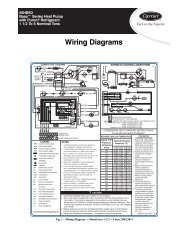
<strong>Wiring</strong> <strong>Diagrams</strong><br />
60 Hz<br />
WIRING DIAGRAM INDEX<br />
Fig. No.<br />
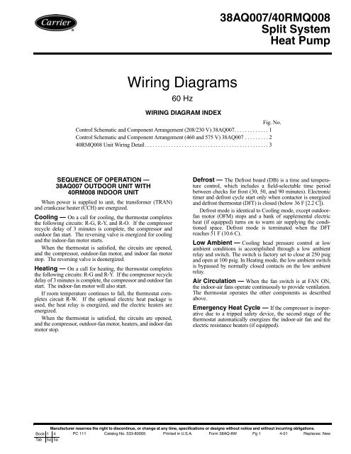
Control Schematic and Component Arrangement (208/230 V) 38AQ007. . . . . . . . . . . . . 1<br />
Control Schematic and Component Arrangement (460 and 575 V) 38AQ007 . . . . . . . . . 2<br />
40RMQ008 Unit <strong>Wiring</strong> Detail. . . . . . . . . . . . . . . . . . . . . . . . . . . . . . . . . . . . . . . . . . . . . . . 3<br />
SEQUENCE OF OPERATION —<br />
38AQ007 OUTDOOR UNIT WITH<br />
40RM008 INDOOR UNIT<br />
When power is supplied to unit, the transformer (TRAN)<br />
and crankcase heater (CCH) are energized.<br />
Cooling — On a call for cooling, the thermostat <strong>com</strong>pletes<br />
the following circuits: R-G, R-Y, and R-O. If the <strong>com</strong>pressor<br />
recycle delay of 3 minutes is <strong>com</strong>plete, the <strong>com</strong>pressor and<br />
outdoor fan start. The reversing valve is energized for cooling<br />
and the indoor-fan motor starts.<br />
When the thermostat is satisfied, the circuits are opened,<br />
and the <strong>com</strong>pressor, outdoor-fan motor, and indoor fan motor<br />
stop. The reversing valve is deenergized.<br />
Heating — On a call for heating, the thermostat <strong>com</strong>pletes<br />
the following circuits: R-G and R-Y. If the <strong>com</strong>pressor recycle<br />
delay of 3 minutes is <strong>com</strong>plete, the <strong>com</strong>pressor and outdoor fan<br />
start. The indoor-fan motor will also start.<br />
If room temperature continues to fall, the thermostat <strong>com</strong>pletes<br />
circuit R-W. If the optional electric heat package is<br />
used, the heat relay is energized, and the electric heaters are<br />
energized.<br />
When the thermostat is satisfied, the circuits are opened,<br />
and the <strong>com</strong>pressor, outdoor-fan motor, heaters, and indoor-fan<br />
motor stop.<br />
Defrost — The Defrost board (DB) is a time and temperature<br />
control, which includes a field-selectable time period<br />
between checks for frost (30, 50, and 90 minutes). Electronic<br />
timer and defrost cycle start only when contactor is energized<br />
and defrost thermostat (DFT) is closed (below 36 F [2.2 C]).<br />
Defrost mode is identical to Cooling mode, except outdoorfan<br />
motor (OFM) stops and a bank of supplemental electric<br />
heat (if equipped) turns on to warm air supplying the conditioned<br />
space. Defrost mode is terminated when the DFT<br />
reaches 51 F (10.6 C).<br />
Low Ambient — Cooling head pressure control at low<br />
ambient conditions is ac<strong>com</strong>plished through a low ambient<br />
relay and switch. The switch is factory set to close at 250 psig<br />
and open at 100 psig. In Heating mode, the low ambient switch<br />
is bypassed by normally closed contacts on the low ambient<br />
relay.<br />
Air Circulation — When the fan switch is at FAN ON,<br />
the indoor-air fans operate continuously to provide ventilation.<br />
The thermostat operates the other <strong>com</strong>ponents as described<br />
above.<br />
Emergency Heat Cycle — If the <strong>com</strong>pressor is inoperative<br />
due to a tripped safety device, the second stage of the<br />
thermostat automatically energizes the indoor-air fan and the<br />
electric resistance heaters (if equipped).<br />
Manufacturer reserves the right to discontinue, or change at any time, specifications or designs without notice and without incurring obligations.<br />
Book 1 4 PC 111 Catalog No. 533-80005 Printed in U.S.A. Form 38AQ-8W Pg 1 4-01 Replaces: New<br />
Tab 5a 5a
LOW AMBIENT<br />
SWITCH<br />
BL<br />
3<br />
LOW 1<br />
AMBIENT<br />
RELAY<br />
COIL<br />
CONNECTION DIAGRAM<br />
2<br />
BK<br />
R<br />
BL<br />
PL<br />
G<br />
BL (WHEN<br />
USED)<br />
PRI<br />
TRANS<br />
SEC<br />
CAP<br />
BL BR<br />
BK BR R<br />
FM<br />
T3 T2<br />
COMP<br />
T1<br />
R<br />
R<br />
BL<br />
R<br />
BK<br />
R<br />
BL<br />
BL<br />
BL<br />
T3<br />
T2<br />
T1<br />
DEFROST Y-RV<br />
CONTROL<br />
FAN<br />
R-RV<br />
O<br />
R<br />
COIL<br />
BK<br />
R<br />
DANGER: ELECTRICAL SHOCK HAZARD<br />
DISCONNECT POWER BEFORE SERVICING<br />
R<br />
L3<br />
L2<br />
L1<br />
C<br />
O<br />
BL<br />
RV<br />
CC<br />
PS2<br />
PS1<br />
DF<br />
BK<br />
Y<br />
W<br />
W<br />
Y<br />
O<br />
L2<br />
BK<br />
L1<br />
CCH<br />
BK<br />
BK<br />
BL<br />
BL<br />
Y<br />
Y<br />
BK<br />
BK<br />
L3<br />
RV<br />
COIL<br />
SEN<br />
POWER SUPPLY PER<br />
N.E.C. AND LOCAL<br />
CODES 208/230 VAC,<br />
60 HZ, 3 PH.<br />
GROUND EQUIPMENT<br />
PER N.E.C. AND<br />
LOCAL CODES.<br />
ATTACH GROUND<br />
PS2<br />
PS1<br />
LP/HP<br />
LP/HP<br />
TWO SWITCH WIRING<br />
DEFROST HEAT<br />
COMPRESSOR<br />
HEAT/COOL<br />
COMMON<br />
24 VAC<br />
L3<br />
T3<br />
RESET<br />
+t°<br />
CONTACTOR<br />
LADDER<br />
FAN<br />
Y-RV<br />
RV<br />
DIAGRAM<br />
208/230 VAC, 60 HZ, 3 PH POWER SUPPLY<br />
T3<br />
CAP<br />
FM<br />
COMPRESSOR<br />
T1 L1<br />
CONT.<br />
RV<br />
COIL<br />
C<br />
CC<br />
DEFROST<br />
COIL<br />
CONTROL PS2<br />
R-<br />
RV<br />
208/230V<br />
24V<br />
CONTACTOR<br />
T2<br />
T1<br />
CCH<br />
PS1<br />
DF<br />
R C O Y W<br />
LAR<br />
1<br />
L2<br />
T2<br />
LAS<br />
2<br />
LOW AMBIENT<br />
RELAY<br />
LP/HP<br />
SEN<br />
DFC<br />
FAN<br />
(WHEN<br />
USED)<br />
TRANSFORMER NOTE 4<br />
DEFROST HEAT<br />
COMPRESSOR<br />
HEAT/COOL<br />
COMMON<br />
24 VAC<br />
LEGEND<br />
C — Contactor LP — Low-Pressure Switch<br />
CAP — Capacitor PL — Plug<br />
CCH — Crankcase Heater PS — Pressure Switch<br />
COMP — Compressor RV — Reversing Valve<br />
DFC — Defrost Control TRANS — Transformer<br />
DFR — Defrost Relay Factory Power <strong>Wiring</strong><br />
FM — Fan Motor Factory Control <strong>Wiring</strong><br />
HP — High-Pressure Switch Field Control <strong>Wiring</strong><br />
LAS — Low Ambient Switch Field Power <strong>Wiring</strong><br />
LAR — Low Ambient Relay<br />
NOTES:<br />
1. Factory wiring is in accordance with National Electrical Code (NEC). Field<br />
modifications or additions must be in <strong>com</strong>pliance with all applicable codes.<br />
2. Use copper conductors only.<br />
3. CAUTION: Not suitable for use on systems exceeding 150 volts to ground.<br />
4. Manual reset circuit breaker is integeral to the transformer.<br />
Fig. 1 — Control Schematic and Component Arrangement — 38AQ007 (208/230 V)<br />
2
BL<br />
R<br />
LOW AMBIENT<br />
SWITCH<br />
3<br />
LOW 1<br />
AMBIENT<br />
RELAY<br />
COIL<br />
CONNECTION DIAGRAM<br />
2<br />
BL<br />
PL<br />
G<br />
CAP<br />
BL BR<br />
BK BR R<br />
FM<br />
R<br />
BL<br />
PRI<br />
TRANS<br />
SEC<br />
BL<br />
BL<br />
R<br />
BK<br />
COIL<br />
FAN<br />
3<br />
1<br />
DEFROST<br />
RELAY<br />
R<br />
BL<br />
2<br />
R-RV<br />
O<br />
R<br />
T3 T2<br />
COMP<br />
T1<br />
DANGER: ELECTRICAL SHOCK HAZARD<br />
DISCONNECT POWER BEFORE SERVICING<br />
BK<br />
Y<br />
DEFROST<br />
CONTROL<br />
R<br />
BK<br />
C<br />
O<br />
BL<br />
R<br />
Y-RV<br />
RV<br />
CC<br />
PS2<br />
PS1<br />
DF<br />
T3<br />
T2<br />
T1<br />
Y<br />
COIL<br />
W<br />
W<br />
Y<br />
O<br />
LEGEND<br />
C — Contactor LP — Low-Pressure Switch<br />
CAP — Capacitor PL — Plug<br />
CCH — Crankcase Heater PS — Pressure Switch<br />
COMP — Compressor RV — Reversing Valve<br />
DFC — Defrost Control TRANS — Transformer<br />
DFR — Defrost Relay Factory Power <strong>Wiring</strong><br />
FM — Fan Motor Factory Control <strong>Wiring</strong><br />
HP — High-Pressure Switch Field Control <strong>Wiring</strong><br />
LAS — Low Ambient Switch Field Power <strong>Wiring</strong><br />
LAR — Low Ambient Relay<br />
L3<br />
L2<br />
L1<br />
BK<br />
BK<br />
BL<br />
BL<br />
Y<br />
Y<br />
BK<br />
BK<br />
L2<br />
BK<br />
L1<br />
ATTACH<br />
BK<br />
GROUND<br />
RV<br />
COIL<br />
SEN<br />
NOTES:<br />
1. Factory wiring is in accordance with National Electrical Code (NEC). Field<br />
modifications or additions must be in <strong>com</strong>pliance with all applicable codes.<br />
2. Use copper conductors only.<br />
3. CAUTION: Not suitable for use on systems exceeding 150 volts to ground.<br />
4. Manual reset circuit breaker is integeral to the transformer.<br />
Y<br />
BL<br />
R<br />
575/460 VAC<br />
60 HZ 3PH<br />
L3<br />
CCH<br />
PS2<br />
PS1<br />
LP/HP<br />
LP/HP<br />
TWO SWITCH WIRING<br />
DEFROST HEAT<br />
COMPRESSOR<br />
HEAT/COOL<br />
COMMON<br />
24 VAC<br />
L3<br />
T3<br />
RESET<br />
T3<br />
CAP<br />
FM<br />
24V<br />
LADDER DIAGRAM<br />
575/460 VAC 60 HZ 3PH<br />
T2<br />
T1<br />
COMPRESSOR<br />
DFR<br />
RV<br />
Y-RV<br />
COIL<br />
FAN<br />
RV<br />
C<br />
DEFROST CC<br />
COIL<br />
CONTROL PS2<br />
R-<br />
RV<br />
+t°<br />
CONTACTOR<br />
575/460V<br />
CCH<br />
CONTACTOR<br />
PS1<br />
DF<br />
R C O Y W<br />
LAR<br />
L2<br />
T2<br />
LAS<br />
1 2 3<br />
LOW AMBIENT<br />
RELAY<br />
TRANSFORMER NOTE 4<br />
Fig. 2 — Control Schematic and Component Arrangement — 38AQ007 (460 and 575 V)<br />
T1 L1<br />
CONT.<br />
LP/HP<br />
SEN<br />
1<br />
DEFROST<br />
RELAY<br />
DEFROST HEAT<br />
COMPRESSOR<br />
HEAT/COOL<br />
COMMON<br />
24 VAC<br />
3
LEGEND<br />
IFC — Indoor-Fan Contactor Factory <strong>Wiring</strong><br />
IFM — Indoor-Fan Motor Field Control <strong>Wiring</strong><br />
TB — Terminal Block<br />
TSTAT — Thermostat<br />
NOTES:<br />
1. Factory wiring is in accordance with National Electrical Code (NEC). Field<br />
modifications or additions must be in <strong>com</strong>pliance with all applicable codes.<br />
2. Use copper conductors only.<br />
Fig. 3 — 40RMQ008 <strong>Wiring</strong> Detail<br />
Copyright 2001 Carrier Corporation<br />
Manufacturer reserves the right to discontinue, or change at any time, specifications or designs without notice and without incurring obligations.<br />
Book 1 4 PC 111 Catalog No. 533-80005 Printed in U.S.A. Form 38AQ-8W Pg 4 4-01 Replaces: New<br />
Tab 5a 5a


