SERVICE MANUAL - Scotsman
SERVICE MANUAL - Scotsman
SERVICE MANUAL - Scotsman

Create successful ePaper yourself
Turn your PDF publications into a flip-book with our unique Google optimized e-Paper software.
MC 16 – MC 46<br />
MF 56 –MFE 61 - MF 83<br />
MV 450 – MV 600<br />
MV 800 - MV 1000<br />
REMOTE AIR COOLED<br />
CONDENSER<br />
<strong>SERVICE</strong> <strong>MANUAL</strong>
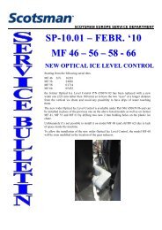
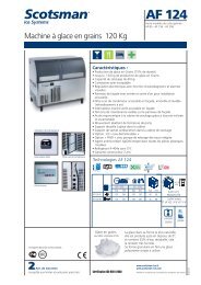
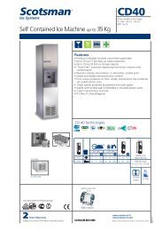
HORIZONTAL INSTALLATION (RECOMMANDED)<br />
450<br />
A<br />
A<br />
622<br />
383<br />
B<br />
B<br />
VERTICAL INSTALLATION<br />
A<br />
A<br />
314<br />
408<br />
B<br />
B<br />
180<br />
1 FAN MOTOR 2 FAN MOTORS 3 FAN MOTORS<br />
A mm 560 1340 1980<br />
B mm 439 1139 1779
WEATHER PROOF AIR COOLED REMOTE<br />
CONDENSER<br />
The remote condenser versions of Cubers and<br />
Flakers are similar to the air cooled standard<br />
versions with the only difference of the remote<br />
condenser and, on MC and MF series, of the Fan<br />
Speed Control used to supply power to the fan<br />
motor/s.<br />
Technical specifications<br />
1. Remote air cooled condenser fit on proper<br />
brackets for horizontal and vertical<br />
installation (MV series for vertical<br />
installation only).<br />
Cooling capacity with ∆T 15K is 3750<br />
Kcal/hr on MC 16, MC 46 and MF 56 and<br />
on MV 450, MV 600 and MV 1000 old<br />
style; 9000 Kcal/hr on MFE 61; 17700<br />
Kcal/hr on MF 83.<br />
2. Fan motor/s 220-240/50-60/1 - 135 Watts<br />
- 0,6 Amps with IP 44 protection (against<br />
liquids and solids) and flow rate of 2150<br />
m³/hr (2 motors on MFE 61; 3 motors on<br />
MF 83).<br />
3. On MC and MF series only, an Electronic<br />
Fan Speed Control set to 16 bar. On MV<br />
series a standard ON-OFF hi pressure<br />
control (15÷17 bars).<br />
4. Pre-charged refrigerant lines of 10 meters<br />
length equipped with AEROQUIP quick<br />
connections.<br />
5. Hi pressure safety control (manual reset<br />
type) set to 34 bar on MC and MF series<br />
(in place of the condenser temperature<br />
sensor) and to 30 bar on MV series.<br />
6. Hi pressure control warning light.<br />
Installation of the remote air cooled condenser<br />
and pre-charged refrigerant lines<br />
A. Location considerations:<br />
Select the best available place protected from<br />
dirt/dust.<br />
The weather proof remote air cooled condenser<br />
can be installed indoor as well as outdoor and can<br />
operate under the most different conditions (rain,<br />
wing, snow, etc.)<br />
Use the following formula for planning the location<br />
of the condenser and ice machine.<br />
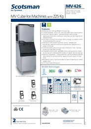
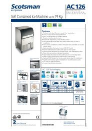
Location Limits – Condenser location must<br />
not exceed ANY of the following limits<br />
Maximum vertical drop dd of 1 meter between the<br />
icemaker and the remote condenser.<br />
Maximum vertical rise rd of 3 meters.<br />
Physical line set maximum length between<br />
icemaker and remote condenser is 10 meters.<br />
Limit to max. one rise and one drop.<br />
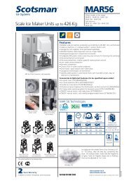
Limit the calculated distance (CD) as per the<br />
Calculation formula to 18 meters.<br />
A = Drop = dd x 6.6<br />
B = Rise = rd x 1.7<br />
C = Horizontal run = hd x 1<br />
CD = A + B + C<br />
hd<br />
Remote Condenser<br />
located ABOVE Ice<br />
Machine<br />
Condenser Distance &<br />
Location Schematic<br />
rd<br />
dd<br />
Remote Condenser<br />
located BELOW Ice<br />
Machine
B. Unpacking and inspection:<br />
Visually inspect the exterior of the shipping<br />
container; any severe damage should be reported<br />
to the delivery carrier.<br />
Uncrate the remote condenser and pre-charged<br />
refrigerant lines and inspect for any concealed<br />
damage. Notify carrier of any cancealed damage.<br />
Check that the pre-charged refrigerant lines are<br />
intact, not kinked.<br />
C. Remote condenser installation<br />
Install and attach the remote condenser to the<br />
floor or to the wall of the building using methods<br />
and practices conform to the local building<br />
requirements.<br />
Remove the control box cover from the remote<br />
condenser and connect the electrical power line<br />
coming from the unit following the wires colors.<br />
NOTE. Cable connecting the unit to the remote<br />
condenser is at 230 Volts so it is imperative to<br />
have the cable properly protected inside a plastic<br />
or metal tube according to the local electrical<br />
code/standard.<br />
D. Pre-charged refrigerant lines<br />
The set of pre-charged refrigerant lines consists<br />
of the 3/8" O.D. self sealing gas line and 1/4" O.D.<br />
self sealing liquid line both equipped with 1-20"<br />
UNEF AEROQUIP quick connections on MC 16-<br />
46, MF 56, of 12 mm and 8 mm O.D. on MV 450-<br />
600 and 14 mm and 12 mm O.D. on MV 800-<br />
1000.<br />
On models MFE 61 the pre-charged refrigerant<br />
lines are 1/2" O.D. gas line and 3/8" O.D. liquid<br />
line both equipped with 1-20" UNEF AEROQUIP<br />
quick connections.<br />
On model MF 83 only, 16 mm O.D. gas line and<br />
12 mm O.D. liquid line with AEROQUIP quick<br />
connections too.<br />
Whenever the length of the pre-charged<br />
refrigerant lines are longer then the distance<br />
between the ice maker and the remote condenser<br />
keep the excess portion indoor shaped as a<br />
vertical spiral so to avoid refrigerant trapping.<br />
CAUTION. Each coupling on the pre-charged<br />
refrigerant lines is self-sealed and should be<br />
tightened 1/4 turn more then snug tight.<br />
ALWAYS USE TWO WRANCHES WHEN<br />
TIGHTENING THESE FITTINGS, ONE AS<br />
BACKUP WRENCH TO PREVENT TWISTING<br />
OF TUBING AND POSSIBLE KINKING OR LINE<br />
RUPTURE.<br />
Connect the gas line coupling to the remote<br />
condenser refrigerant fitting (labeled GAS) and to<br />
the refrigerant fitting on the rear side of the ice<br />
machine.<br />
Connect the liquid line coupling to the remote<br />
condenser refrigerant fitting (labeled LIQUID) and<br />
to the refrigerant fitting on the rear side of the ice<br />
machine.<br />
ATTENTION. The inlet of the remote air cooled<br />
condenser (gas) must be always located<br />
above the outlet (liquid) for both horizontal<br />
and vertical installations.<br />
Operating instructions<br />
The remote air cooled condenser versions of<br />
Cubers and Flakers are operating in the same<br />
way as the standard machine.<br />
The only difference is the operation of the fan<br />
motor on MC and MF series as on the remote<br />
condenser versions it is no longer possible to use<br />
the condenser sensor to control the ON-OFF<br />
operation of the same.<br />
In place of the condenser sensor has been<br />
installed an electronic fan speed control (set up at<br />
16 bar by its adjusting screw) and a manual reset<br />
type hi pressure control.<br />
The fan speed control supplies a variable power<br />
to the fan motor so to modulate its speed and<br />
keep to a constant value the discharge pressure.<br />
The hi pressure control is used only as a safety<br />
device to switch OFF the operation of the machine<br />
in case of fan motor failure.<br />
MC 16-46<br />
MF 56<br />
MV 450-600-1000<br />
OLD STYLE<br />
MFE 61 MF 83<br />
Remote air cooled condenser & fan motor assy 620418 00 620418 00 620418 01 620418 02<br />
Fan motor assy - LU.VE.-CONTARDO 001028 30 001028 30 001028 30 *****<br />
Fan motor assy - ECO 001028 32 ***** 001028 32 001028 32<br />
Hi pressure control (safety) 620498 00 620231 01 620498 00 620498 00<br />
Fan speed control/Electronic device 620500 00 ***** 620500 00 620500 00<br />
Fan pressure control ***** CM 19550624 ***** *****<br />
Low pressure control ***** ***** ***** 620451 00<br />
Liquid receiver ***** CM 19635339 ***** *****<br />
AEROQUIP male connection - LIQUID 650438 01 650438 01 650438 00 650438 00<br />
AEROQUIP female connection - LIQUID 650437 01 650437 01 650437 00 650437 00<br />
AEROQUIP male connection - GAS 650438 01 650438 01 650438 00 650438 05<br />
AEROQUIP female connection - GAS 650437 01 650437 01 650437 00 650437 05
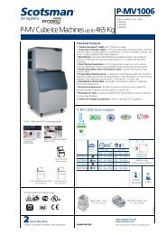
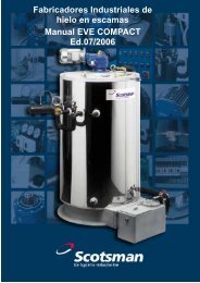
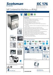
SCK1<br />
FOR MC46<br />
PER MC46<br />
EVAP. TEMP.<br />
SENSOR<br />
SENSORE<br />
TEMP. EVAP.<br />
COND. TEMP.<br />
SENSOR<br />
SENSORE<br />
TEMP. COND.<br />
BIN FULL<br />
SENSOR<br />
SENSORE<br />
CONT. PIENO<br />
WATER<br />
PUMPS<br />
HOT GAS VALVES<br />
WATER INLET<br />
VALVES<br />
POMPE<br />
ACQUA ELETTROVALVOLE GAS CALDO ELETTROVALVOLE<br />
INGRESSO ACQUA<br />
WATER DISCHARGE HI PRESSURE FAN<br />
VALVES SWITCH MOTOR CRANCKCASE HEATER<br />
ELETTROVALVOLE<br />
SCARICO ACQUA<br />
PRESSOSTATO<br />
DI ALTA<br />
VENTILATORE<br />
RESISTENZA COMPRESSORE
COMPRESSOR<br />
SCK1<br />
FOR MC46<br />
PER MC46<br />
MODEL WITHOUT NEUTRAL<br />
PER I MODELLI SENZA NEUTRO<br />
EVAP. TEMP.<br />
SENSOR<br />
SENSORE<br />
TEMP. EVAP.<br />
COND. TEMP.<br />
SENSOR<br />
SENSORE<br />
TEMP. COND.<br />
BIN FULL<br />
SENSOR<br />
SENSORE<br />
CONT. PIENO<br />
WATER<br />
PUMPS<br />
HOT GAS<br />
VALVES<br />
WATER INLET<br />
VALVES<br />
POMPE<br />
ELETTROVALVOLE ELETTROVALVOLE<br />
ACQUA GAS CALDO INGRESSO ACQUA<br />
VENTILATORE<br />
COMPRESSORE<br />
WATER DISCHARGE HI PRESSURE FAN<br />
VALVES SWITCH MOTOR CRANCKCASE HEATER<br />
ELETTROVALVOLE<br />
SCARICO ACQUA<br />
PRESSOSTATO<br />
DI ALTA<br />
RESISTENZA COMPRESSORE
M2<br />
R1<br />
SA1<br />
SB1<br />
SP2<br />
SP3<br />
SP4<br />
ST1<br />
TM1<br />
TM1<br />
Drive motor<br />
Motoriduttore<br />
Cranckcase heater<br />
Resistenza compressore<br />
Switch<br />
Interruttore<br />
Reset push button<br />
Pulsante reset<br />
HI pressure control safety<br />
Pressostato sicurezza alta pressione<br />
Water pressure control<br />
Controllo bassa pressione acqua<br />
LOW pressure control<br />
Pressostato basa pressione<br />
Thermostat<br />
Termostato<br />
Compressor thermal relay<br />
RelŁ protezione termica compressore<br />
Compressor thermal protector<br />
Protettore termico compressore<br />
EV1<br />
FAN motor<br />
Ventilatore<br />
HL6<br />
Bin full<br />
Magazzino pieno<br />
EV2<br />
FAN motor<br />
Ventilatore<br />
HL7<br />
Wrong phase alarm<br />
Allarme sequenza fasi<br />
EV3<br />
FAN motor<br />
Ventilatore<br />
HL8<br />
Current drive-motor alarm<br />
Allarme amperometrica motoriduttore<br />
F1<br />
3-phase monitoring relay<br />
controllo sequenza fasi<br />
HL9<br />
Compressor thermal protector alarm<br />
Allarme protezione termica compressore<br />
FC1<br />
Spout switch<br />
Interruttore bocchetta<br />
KA1<br />
Current drive-motor relay<br />
RelŁ amperometrico motoriduttore<br />
FSC1<br />
Fan Speed<br />
Fan Speed<br />
KA3<br />
Drive-motor start relay<br />
RelŁ anticipata motoriduttore<br />
HL1<br />
Power ON<br />
Macchina in funzione<br />
KM1<br />
Compressor contactor<br />
Teleruttore compressore<br />
HL2<br />
HI pressure alarm<br />
Allarme alta pressione<br />
KM2<br />
Drive-motor contactor<br />
Teleruttore motoriduttore<br />
HL3<br />
LOW pressure alarm<br />
Allarme bassa pressione<br />
KT1<br />
Compressor timer delay<br />
Ritardatore compressore<br />
HL4<br />
Water alarm<br />
Allarme mancanza acqua<br />
KT2<br />
Drive-motor timer delay<br />
Ritardatore motoriduttore<br />
HL5<br />
Spout switch light<br />
Spia interruttore bocchetta<br />
M1<br />
Compressor<br />
Compressore