MMI 810.1 / 811.1 Gas burner automatic safety control - Seltron
MMI 810.1 / 811.1 Gas burner automatic safety control - Seltron
MMI 810.1 / 811.1 Gas burner automatic safety control - Seltron

You also want an ePaper? Increase the reach of your titles
YUMPU automatically turns print PDFs into web optimized ePapers that Google loves.
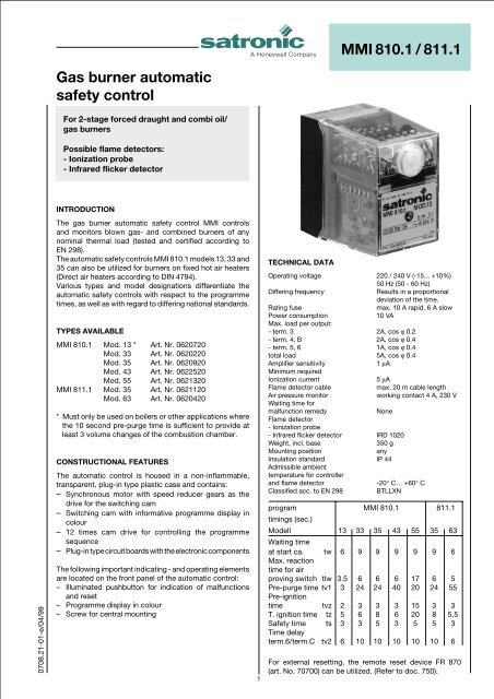
A Honeywell Company <strong>MMI</strong> <strong>810.1</strong> / <strong>811.1</strong><br />
<strong>Gas</strong> <strong>burner</strong> <strong>automatic</strong><br />
<strong>safety</strong> <strong>control</strong><br />
For 2-stage forced draught and combi oil/<br />
gas <strong>burner</strong>s<br />
Possible flame detectors:<br />
- Ionization probe<br />
- Infrared flicker detector<br />
INTRODUCTION<br />
The gas <strong>burner</strong> <strong>automatic</strong> <strong>safety</strong> <strong>control</strong> <strong>MMI</strong> <strong>control</strong>s<br />
and monitors blown gas- and combined <strong>burner</strong>s of any<br />
nominal thermal load (tested and certified according to<br />
EN 298).<br />
The <strong>automatic</strong> <strong>safety</strong> <strong>control</strong>s <strong>MMI</strong> <strong>810.1</strong> models 13, 33 and<br />
35 can also be utilized for <strong>burner</strong>s on fixed hot air heaters<br />
(Direct air heaters according to DIN 4794).<br />
Various types and model designations differentiate the<br />
<strong>automatic</strong> <strong>safety</strong> <strong>control</strong>s with respect to the programme<br />
times, as well as with regard to differing national standards.<br />
0708.21-01-e/04/99<br />
TYPES AVAILABLE<br />
<strong>MMI</strong> <strong>810.1</strong> Mod. 13 * Art. Nr. 0620720<br />
Mod. 33 Art. Nr. 0620220<br />
Mod. 35 Art. Nr. 0620920<br />
Mod. 43 Art. Nr. 0622520<br />
Mod. 55 Art. Nr. 0621320<br />
<strong>MMI</strong> <strong>811.1</strong> Mod. 35 Art. Nr. 0621120<br />
Mod. 63 Art. Nr. 0620420<br />
* Must only be used on boilers or other applications where<br />
the 10 second pre-purge time is sufficient to provide at<br />
least 3 volume changes of the combustion chamber.<br />
CONSTRUCTIONAL FEATURES<br />
The <strong>automatic</strong> <strong>control</strong> is housed in a non-inflammable,<br />
transparent, plug-in type plastic case and contains:<br />
– Synchronous motor with speed reducer gears as the<br />
drive for the switching cam<br />
– Switching cam with informative programme display in<br />
colour<br />
– 12 times cam drive for <strong>control</strong>ling the programme<br />
sequence<br />
– Plug-in type circuit boards with the electronic components<br />
The following important indicating - and operating elements<br />
are located on the front panel of the <strong>automatic</strong> <strong>control</strong>:<br />
– Illuminated pushbutton for indication of malfunctions<br />
and reset<br />
– Programme display in colour<br />
– Screw for central mounting<br />
1<br />
TECHNICAL DATA<br />
Operating voltage 220 / 240 V (-15... +10%)<br />
50 Hz (50 - 60 Hz)<br />
Differing frequency<br />
Results in a proportional<br />
deviation of the time.<br />
Rating fuse<br />
max. 10 A rapid, 6 A slow<br />
Power consumption<br />
10 VA<br />
Max. load per output:<br />
- term. 3 2A, cos ϕ 0.2<br />
- term. 4, B 2A, cos ϕ 0.4<br />
- term. 5, 6 1A, cos ϕ 0.4<br />
total load 5A, cos ϕ 0.4<br />
Amplifier sensitivity 1 µA<br />
Minimum required<br />
Ionization current 5 µA<br />
Flame detector cable<br />
max. 20 m cable length<br />
Air pressure monitor<br />
working contact 4 A, 230 V<br />
Waiting time for<br />
malfunction remedy<br />
None<br />
Flame detector<br />
- Ionization probe<br />
- Infrared flicker detector IRD 1020<br />
Weight, incl. base<br />
350 g<br />
Mounting position<br />
any<br />
Insulation standard IP 44<br />
Admissible ambient<br />
temperature for <strong>control</strong>ler<br />
and flame detector<br />
-20° C… +60° C<br />
Classified acc. to EN 298<br />
BTLLXN<br />
program <strong>MMI</strong> <strong>810.1</strong> <strong>811.1</strong><br />
timings (sec.)<br />
Modell 13 33 35 43 55 35 63<br />
Waiting time<br />
at start ca. tw 6 9 9 9 9 9 6<br />
Max. reaction<br />
time for air<br />
proving switch tlw 3.5 6 6 6 17 6 5<br />
Pre-purge time tv1 3 24 24 40 20 24 55<br />
Pre-ignition<br />
time tvz 2 3 3 3 15 3 3<br />
T. ignition time tz 5 6 8 6 20 8 5.5<br />
Safety time ts 3 3 5 3 5 5 3<br />
Time delay<br />
term.6/term.C tv2 6 10 10 10 10 10 6<br />
For external resetting, the remote reset device FR 870<br />
(art. No. 70700) can be utilized. (Refer to doc. 750).
APPLICATION TECHNOLOGY FEATURES<br />
CO<strong>MMI</strong>SSIONING AND SERVICE/MAINTENANCE<br />
1. Flame Monitoring<br />
The flame monitoring can be effected with the following<br />
flame detectors:<br />
- With ionization electrodes in power grids with earthed<br />
neutral conductor, utilizable with gas <strong>burner</strong>s (interference<br />
effects of the ignition spark cannot influence the formation<br />
of the flame signal).<br />
- With infrared flicker detector type IRD 1020 for all types<br />
of <strong>burner</strong>s.<br />
2. Burner Control<br />
– The <strong>burner</strong> <strong>control</strong>s features a low-voltage protection. If<br />
the supply voltage dropps below 160 V during operation,<br />
the <strong>burner</strong> switches-off. When the supply voltage raises<br />
above 180 V, the <strong>burner</strong> performs a restart independently.<br />
– The <strong>automatic</strong> <strong>burner</strong> <strong>control</strong>s <strong>MMI</strong> only operate, when a<br />
load is connected to terminal 5. If the fuel valve is<br />
interrupted by an external contact during the pre-purging<br />
phase, a resistance of max. 22 kW, 4 Watt has to be<br />
applied bet-ween the terminals 5 and 8.<br />
– Functional test of the air pressure monitor before the<br />
startup and monitoring of the air pressure during the prepurging<br />
time, as well as in the operating condition of the<br />
<strong>burner</strong>. For normal applications a working contact with a<br />
power rating of 4 A / 230 V is sufficient.<br />
– In the case of the <strong>automatic</strong> <strong>control</strong> <strong>MMI</strong> <strong>810.1</strong>, contacts<br />
can be installed between the terminals 1 and 9 (e.g., valve<br />
limit position contacts). These are checked for their<br />
correct closing position when the unit is started up. The<br />
connection 1 - 9 has to be closed during the starting<br />
phase of the <strong>automatic</strong> <strong>control</strong>.<br />
3. Safety<br />
With respect to design and programme sequence, the gas<br />
<strong>burner</strong> <strong>automatic</strong> <strong>safety</strong> <strong>control</strong>s of the <strong>MMI</strong> type range<br />
comply with the currently applicable European standards<br />
and regulations.<br />
4. Mounting and Electrical Installation<br />
On the base:<br />
– 3 earth conductor terminals with additional strap for the<br />
earthing of the <strong>burner</strong>.<br />
– 3 neutral conductor terminals with an internal, fixed<br />
connection to the neutral conductor input, terminal 8.<br />
– 2 individual slide-in plates and 2 fixed knock-out apertures<br />
with thread PG 11, as well as 2 knock-out apertures from<br />
below, make the wiring of the base more easy.<br />
General:<br />
– Mounting position as required, insulation standard IP 44<br />
(splash-proof). The <strong>automatic</strong> <strong>control</strong> and sensor should,<br />
however, not be exposed to excessive vibration.<br />
– During mounting and installation, the applicable regulations<br />
for installation have to be observed.<br />
1. Important Remarks<br />
– Before commissioning, the wiring has to be accurately<br />
checked. Faulty wiring can damage the unit and endanger<br />
the <strong>safety</strong> of the installation.<br />
– The mains fuse has to be selected so that the limit values<br />
indicated under "Technical Specifications" are under no<br />
circumstances exceeded. Non-compliance with this<br />
regulation can have very serious consequences for the<br />
<strong>control</strong> unit and for the installation in the case of a shortcircuit.<br />
– For <strong>safety</strong> reasons, at least one <strong>control</strong> shut-down per 24<br />
hours must be assured.<br />
– The <strong>control</strong> unit must be plugged-in or -out only when the<br />
mains supply has been disconnected.<br />
– Automatic <strong>burner</strong> <strong>safety</strong> <strong>control</strong>s are <strong>safety</strong> devices and<br />
must not be opened.<br />
2. Functional Check<br />
During commissioning and after an overhaul of the <strong>burner</strong>,<br />
the following checks have to be carried out:<br />
a) Starting test with closed manual valve and bridged gas<br />
monitor contact:<br />
– The device must go into a fault condition after the<br />
<strong>safety</strong> period has elapsed.<br />
b) Close the manual valve in operating position with the gas<br />
monitor contact bridged.<br />
– The device must go into a fault condition after a flame<br />
failure.<br />
c) Air pressure monitor contact interrupted:<br />
– Device goes into a fault condition.<br />
d) Bridge air pressure monitor contact before starting:<br />
– Device must not start.<br />
3. Trouble Shooting<br />
Burner does not go into operation, programme indication<br />
remains:<br />
– Electrical connection defective.<br />
– Thermostat or gas monitor "OFF".<br />
Burner does not go into operation, programme indication<br />
rotates continuously:<br />
– Air pressure monitor defective, respectively, not in starting<br />
position. (Working contact must be open).<br />
– Connection term. 1 - term. 9 interrupted<br />
– mains voltage < 180V<br />
The <strong>automatic</strong> <strong>control</strong> switches to fault condition shortly<br />
after the start of the pre-purge time (line within the blue<br />
zone):<br />
– Air pressure monitor contact does not close.<br />
– No load on terminal 5.<br />
– Flame signal.<br />
Automatic <strong>control</strong> switches to fault condition during the prepurging<br />
(blue zone):<br />
– No flame formation (ignition missing, valve does not<br />
open, etc.)<br />
– No flame signal or too weak flame signal (flame does not<br />
adhere, poor insulation of the flame detector, <strong>burner</strong> not<br />
properly connected to the earth conductor).<br />
2<br />
Automatic <strong>control</strong> switches to fault condition during the<br />
operating position (red, resp. green zone):<br />
– Flame lift-off<br />
– Air pressure monitor contact opens<br />
– Flame signal too weak.<br />
<strong>MMI</strong> <strong>810.1</strong> / <strong>811.1</strong>
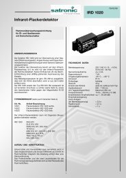
SCHEMATIC CONNECTION DIAGRAM AND PROCESS DIAGRAM <strong>MMI</strong> <strong>810.1</strong><br />
Ph<br />
max. 10 A rapid<br />
6 A slow<br />
HS<br />
GW<br />
ST<br />
RT<br />
1 2 A/3 4 5 6 B 7 8 9 C<br />
LW<br />
IS Z M V1 V2 SA<br />
N<br />
Ph<br />
max. 10 A rapid<br />
6 A slow<br />
HS<br />
tw tlw tv1 tvz tz<br />
1 2 A/3 4 5 6 B 7 8 9 C<br />
SV<br />
LW<br />
ST<br />
RT<br />
ts tv2<br />
SCHEMATIC CONNECTION DIAGRAM AND PROCESS DIAGRAM <strong>MMI</strong> <strong>811.1</strong><br />
GW<br />
HS<br />
GW<br />
ST<br />
RT<br />
IS<br />
Z<br />
M<br />
V1<br />
V2<br />
LW<br />
SA<br />
SV<br />
tw<br />
tlw<br />
tv1<br />
tvz<br />
tz<br />
ts<br />
tv2<br />
Main switch<br />
<strong>Gas</strong> pressure switch<br />
Limit thermostat<br />
Control thermostat<br />
Ionization probe<br />
Ignition<br />
Burner motor<br />
Solenoid valve 1st stage<br />
Solenoid valve 2nd stage<br />
Air pressure monitor<br />
External fault indication<br />
Safety valve<br />
Waiting time at start-up<br />
Max. reaction time<br />
for air proving switch<br />
Pre-purge time<br />
Pre-ignition time<br />
Total ignition time<br />
Safety time<br />
Time delay term.6 / term.C<br />
N<br />
IS Z M V1 V2 SA<br />
tw tlw tv1 tvz tz<br />
ts tv2<br />
IRD CONNECTION<br />
IRD 1020<br />
blue<br />
black<br />
brown<br />
term. 8<br />
term. 2<br />
term. 9<br />
SCHEMATIC DIAGRAM <strong>MMI</strong> <strong>810.1</strong> SCHEMATIC DIAGRAM <strong>MMI</strong> <strong>811.1</strong><br />
<strong>MMI</strong> <strong>810.1</strong> / <strong>811.1</strong><br />
3
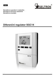
<strong>MMI</strong> WITH BASE<br />
5<br />
MEASUREMENT OF THE FLAME SIGNAL<br />
E<br />
2<br />
<strong>MMI</strong> <strong>810.1</strong> / <strong>MMI</strong> <strong>811.1</strong><br />
91<br />
24 67<br />
PG 11<br />
+<br />
The signal should<br />
be greater than 5 µA<br />
35<br />
44<br />
Reset button<br />
Earth<br />
87<br />
24<br />
30<br />
61<br />
Slide-in plate<br />
-<br />
0 - 10 µA<br />
0 - 100 µA<br />
The Satronic Ionimeter<br />
is ideal for making<br />
this measurement.<br />
25<br />
16<br />
M4<br />
16<br />
30<br />
30<br />
57-60<br />
ø 16 mm,<br />
cable entry from below<br />
IRD 1020<br />
HOLDER M93<br />
29<br />
21.8<br />
ø13.5<br />
50 44<br />
104<br />
14<br />
35<br />
3<br />
4.5<br />
26<br />
15.1<br />
48<br />
17<br />
4<br />
ø20.5<br />
ORDERING INFORMATION<br />
ITEM DESIGNATION ITEM NO.<br />
Control unit Type <strong>MMI</strong> <strong>810.1</strong> mod. 33 0620220<br />
or Type <strong>MMI</strong> <strong>811.1</strong> mod. 35 0621120<br />
Base for <strong>MMI</strong> <strong>810.1</strong> Base 701 TTG-EN 70101<br />
Base for <strong>MMI</strong> <strong>811.1</strong> Base 710 TTG-FN 70102<br />
Slide-in plate PG-plate 70502<br />
optionally Cable clamping plate 70501<br />
Flame detector IRD 1020 end-on viewing 16522<br />
Flame detector IRD 1020 side-on left 16523<br />
Flame detector IRD 1020 side-on right 16521<br />
IRD mounting flange IRD Holder M93 59093<br />
Flame detector cable 3-wire, 0.6 m 7236001<br />
The above ordering information refers to the standard version.<br />
Special versions are also included in our product range.<br />
Specifications subject to change without notice.<br />
<strong>MMI</strong> <strong>810.1</strong> / <strong>811.1</strong><br />
4<br />
A Honeywell Company<br />
Satronic AG<br />
Honeywell-Platz 1<br />
Postfach 324<br />
CH-8157 Dielsdorf