You also want an ePaper? Increase the reach of your titles
YUMPU automatically turns print PDFs into web optimized ePapers that Google loves.
Valid for the following types containing Software Version 2.5x:<br />
MiniMEP 404 S, 2404 S<br />
MiniMEP 424 A, 2424 A, 424A/12V<br />
MiniMEP 434 A, 2434 A<br />
MiniMEP 524 A, 2524 A<br />
MiniMEP 534 A, 2534 A<br />
Brief Description<br />
MiniMEP Recording Systems (dataloggers) are designed for<br />
paperless longtime data recording of temperature values and<br />
(dep. on type) relative humidity. Thus the user is able to get a<br />
proof about the course of temperatures and humidity in<br />
corresponding rooms, without application of additional<br />
components as e.g. mechanical printers or PC's.<br />
It is ideal for compliance with 21 CFR process control for food<br />
storage regulations and HACCP Quality Assurance Systems.<br />
The wide temperature range qualifies a MiniMep for both freezing<br />
applications and 'hot' industrial processes.<br />
The Recording System MiniMEP meets all requirements of<br />
the EU Standard EN 12830.<br />
Functions<br />
� Records the values of temperature sensors resp. humidity<br />
transmitters for up to 20 years !<br />
Adjustable storage interval.<br />
Example 1: 781 days with a 5 minute interval.<br />
Example 2: > 6 years with a 15 min. interval<br />
� Data storage is unlimited even without mains voltage<br />
� Real time clock with typ. 10 years battery backup<br />
� Continuous recording by external lead accu possible *<br />
� Alarm too high/low with time delay for each input<br />
� Monitored sensor inputs<br />
� Error message memory shows the last 6 occured errors<br />
� Clear assignment of measuring position, time and value<br />
plain text designation in the display<br />
� Networkable via interface<br />
� LCD dot matrix display, backlighted, 4 languages<br />
� Display shows actual temperature, time and date<br />
� Lets you view all recorded values any time<br />
� Easy operating by 3 keys<br />
� Digital inputs e.g. for door-contact or other messages *<br />
� Isolated alarm relay and built-in buzzer *<br />
� Four display languages selectable:<br />
german, english, french, dutch<br />
* (not type 404 S, 2404S)<br />
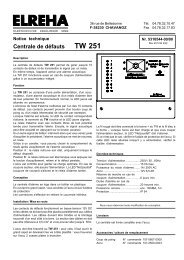
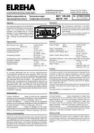
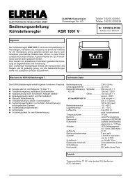
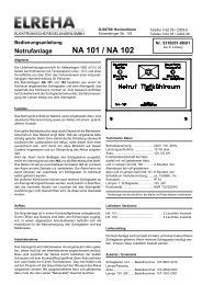
Technical Manual<br />
Temperature- & Humidity Recording System<br />
MiniMEP<br />
Nr. 5310965-00/20 E<br />
02.07.96 12:30<br />
Room 1 -23.5°C<br />
Please note Operating and<br />
Safety Instructions on page 12 !
page 2<br />
Note<br />
The temperature recording system MiniMEP corresponds to<br />
the requirements of the european standard EN 12830.<br />
Please note that according to the standard EN 13486, the<br />
end-user is bound to a continuous check of the units for<br />
operation and accuracy.<br />
General Description<br />
The MiniMEP data logger series is developed for paperless<br />
recording of temperature resp. humidity values and to store them<br />
for a long period of time.<br />
The unit measures temperatures by high accurate platinium<br />
sensors and stores the values in a non-volatile memory for<br />
unlimited time.<br />
Without additional utilities, the user is able to recall every<br />
recorded value with its date, time and position designation.<br />
If this memory is full, the oldest recorded values will be erased to<br />
get space for the newest values.<br />
The units are available in 2 different housings and memory sizes<br />
(see overview below).<br />
A special version (MiniMEP 434 A/534 A) can record 2 temperature<br />
values and the values of two 4...20 mA-humidity transmitters.<br />
Contents<br />
Technical Manual MiniMEP Data Loggers<br />
page<br />
General Description ............................................. 2<br />
Operating ............................................................. 3<br />
Programming Access Authorization,<br />
Reset Error Messages, Buzzer/Relay Test,<br />
Error Messages / -codes<br />
Functional Description ......................................... 4<br />
Programming designations .............................. 4<br />
Parameter listing (2)434A, (2)534A .................... 5<br />
Parameter listing (2)404S, (2)424A, (2)524A ..... 6<br />
Connection, Versions 4xx.................................... 7<br />
Connection, Versions 5xx.................................... 9<br />
Dimensons ........................................................... 10<br />
Processing of Data, PC connection,<br />
Unlock of recording system ................................. 11<br />
Installation ........................................................... 12<br />
Cable lenghts ................................................... 12<br />
Connection and Safety Notes ....................... 12<br />
Accu operation ............................................... 12<br />
Start-up ................................................................ 12<br />
Technical Data / Accessories .............................. 13<br />
CE-Statement of Conformity ............................... 14<br />
Appendix: Drilling template, calibration and start-up report<br />
Type- Housing Inputs Recording Digital Alarm Limits LC- Input for Memory Cap- Supply<br />
Overview Range inputs Alarm relays Display additional- acity with 15<br />
Accu min. interval<br />
MiniMEP 404 S wall mounting 4x temp. -110/+600°C -- -- X -- 366 days 230V<br />
MiniMEP 2404 S wall mounting 4x temp. -110/+600°C -- -- X -- 366 days 115V<br />
MiniMEP 424 A wall mounting 4x temp. -110/+600°C 3x 230V 1x SPDT X X appr. 6 years 230V<br />
MiniMEP 2424 A wall mounting 4x temp. -110/+600°C 3x 115V 1x SPDT X X appr. 6 years 115V<br />
MiniMEP 424/12V wall mounting 4x temp. -110/+600°C 3x 12VDC 1x SPDT X X appr. 6 years 12V<br />
MiniMEP 434 A wall mounting 2x temp. -110/+600°C 3x 230V 1x SPDT X X appr. 6 years 230V<br />
2x humidity 0/100% r.F.<br />
MiniMEP 2434 A wall mounting 2x temp. -110/+600°C 3x 115V 1x SPDT X X appr. 6 years 115V<br />
2x humidity 0/100% r.F.<br />
MiniMEP 524 A panel mounting 4x temp. -110/+600°C 3x 230V 1x SPDT X X appr. 6 years 230V<br />
MiniMEP 2524 A panel mounting 4x temp. -110/+600°C 3x 115V 1x SPDT X X appr. 6 years 115V<br />
MiniMEP 534 A panel mounting 2x temp. -110/+600°C 3x 230V 1x SPDT X X appr. 6 years 230V<br />
2x humidity 0/100% r.F.<br />
MiniMEP 2534 A panel mounting 2x temp. -110/+600°C 3x 115V 1x SPDT X X appr. 6 years 115V<br />
2x humidity 0/100% r.F.
Technical Manual MiniMEP Data Loggers page 3<br />
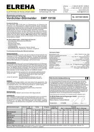
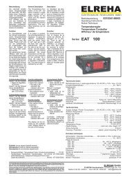
Operating<br />
Organisation of the display pages<br />
All parameters and values are partitioned on four<br />
sensor pages and a parameter page. The sensor<br />
pages contain the recorded values. The parameter<br />
page contains setpoints, times, error messages,<br />
etc. Operating the MiniMEP is very easy by three<br />
keys. Key 'P' changes the pages, with the up/down<br />
buttons you are able to scroll the lists or to change<br />
values.<br />
Read off recorded values<br />
02.07.96 12:27<br />
Sensor 1 -23.5°C<br />
Every push on button 'P' brings you to the<br />
page of the next sensor.<br />
02.07.96 12:15<br />
sensor 1 -23.5°C<br />
After power-up, the<br />
display shows date,<br />
Current time and value<br />
of sensor 1.<br />
Basic settings / Reading Error messages<br />
02.07.96 12:15<br />
sensor 2 -12.0°C<br />
serial no<br />
000000<br />
02.07.96 12:15<br />
sensor 1 -23.5°C<br />
02.07.96 12:00<br />
sensor 1 -23.5°C<br />
02.07.96 11:45<br />
sensor 1 -23.5°C<br />
02.07.96 12:15<br />
sensor 3 21.5°C<br />
Holding the button 'P' for more than 1 sec. brings you to the parameter page. Select parameter<br />
by the 'up/down' keys (see parameter descriptions on the next pages). Holding the 'P' button<br />
again brings you back to the sensor 1 page.<br />
02.07.96 12:15<br />
sensor 1 -23.5°C<br />
Programming / Access Authorization<br />
� Select desired parameter by the 'up/down' keys<br />
� Press 'P'-key short<br />
� An access code is<br />
requested<br />
� Enter access code by<br />
'up/down' keys<br />
Pages<br />
Overview<br />
The code is related from the time of the day as the sum of the hour (0 to 23) plus ‘10’.<br />
Example: At 9:35 a.m. the code is 9 + 10 = 19.<br />
At 9:35 p.m. the code would be 21 + 10 = 31<br />
� Notation of parameter flashes<br />
� Change value by the 'up/down' keys<br />
� Press 'P'-key short<br />
� Select new parameter if necessary<br />
If you have pressed the 'P' key longer than 1 second or no key is pressed for about 1 minute<br />
after entering the code, the display will switch back to the actual value of sensor 1.<br />
By pushing the 'up/down' keys you<br />
can select the desired values.<br />
Every keypress brings you to the<br />
next recorded value. Holding an<br />
'up' or 'down' key effects an<br />
automatic, accelerating scrolling.<br />
P P P<br />
P<br />
P P<br />
Identification 1<br />
entry : > 0 <<br />
Error codes<br />
If a failure occurs, the MiniMEP generates an<br />
error message by de-activating the alarm relay<br />
and switching ON the internal buzzer.<br />
Additionally, the display starts flashing to get<br />
your attention. Each error message has a<br />
priority level. If several messages occur, the<br />
messages with higher priority are displayed on<br />
top, messages with lower priority are blinded<br />
by the higher ones.<br />
x34-types only: If the current inputs<br />
get > 20mA or if they are not connected:<br />
display shows 100%, no error<br />
message.<br />
P<br />
01.07.96 15:00<br />
01.07.96 14:45<br />
01.07.96 14:30<br />
01.07.96 14:15<br />
sensor 1 -1.0°C<br />
01.07.96 15:00<br />
01.07.96 14:45<br />
01.07.96 14:30<br />
01.07.96 14:15<br />
sensor 2 -21.0°C<br />
02.07.96 12:15<br />
sensor 1 -23.5°C<br />
P P<br />
01.07.96 15:00<br />
01.07.96 14:45<br />
01.07.96 14:30<br />
01.07.96 14:15<br />
sensor 3 -24.5°C<br />
01.07.96 15:00<br />
01.07.96 14:45<br />
01.07.96 14:30<br />
01.07.96 14:15<br />
sensor 4 -17.5°C<br />
push for longer<br />
than 1 second<br />
P P<br />
correction<br />
probe selection<br />
MINIMEP<br />
serial no<br />
000000<br />
02.07.96 12:15<br />
sensor 4 -5.5°C<br />
Reading the Current Error<br />
While the display flashes, you can read the<br />
current error by holding<br />
Reset of Error Messages<br />
If an error message occurs,<br />
push shortly<br />
Buzzer and relay will be reset, but will come<br />
back after the set alarm repetition time. If an<br />
error with a higher priority occurs, it will come<br />
at once.<br />
Buzzer / Relay Test<br />
To test, if the internal buzzer and the alarm<br />
relay works correctly,<br />
P<br />
push and<br />
for > 1 sec.<br />
Then parameter (actual error) will be displayed<br />
at the same time while the actual values are<br />
displayed. The buzzer sounds and the relay<br />
switches off as long as you press the keys.<br />
'——' ................... no error<br />
'Poff' .................... main power was switched off<br />
prio.1 ........... 'al1' ...................... digital input 1 (Default=al1) was/is not connected<br />
prio.2 ........... 'al2' ...................... digital input 2 (Default=al2) was/is not connected<br />
prio.3 ........... 'door' ................... digital input 3 (Default=door) was/is not connected<br />
prio.4 ........... probe 1, 'p-break' (sensor is broken) or 'p-short' (sensor has short circuit)<br />
prio.5 ........... probe 2, 'p-break' (sensor is broken) or 'p-short' (sensor has short circuit)<br />
prio.6 ........... probe 3, 'p-break' (sensor is broken) or 'p-short' (sensor has short circuit)<br />
prio.7 ........... probe 4, 'p-break' (sensor is broken) or 'p-short' (sensor has short circuit)<br />
prio.8 ........... 'ot 1' .................... sensor 1 has increased the warning limit<br />
prio.9 ........... 'ot 2' .................... sensor 2 has increased the warning limit<br />
prio.10 ......... 'ot 3' .................... sensor 3 has increased the warning limit<br />
prio.11 ......... 'ot 4' .................... sensor 4 has increased the warning limit<br />
prio.12 ......... 'accu' ................... accu operation after mains is lost<br />
prio.13 ......... 'dch.' .................... accu discharged or defect<br />
prio.14 ......... 'ut 1' .................... sensor 1 has decreased the warning limit<br />
prio.15 ......... 'ut 2' .................... sensor 2 has decreased the warning limit<br />
prio.16 ......... 'ut 3' .................... sensor 3 has decreased the warning limit<br />
prio.17 ......... 'ut 4' .................... sensor 4 has decreased the warning limit<br />
'prb1' to 'prb4' ..... an error is occured on sensor x
page 4<br />
Functions<br />
Error memory<br />
The last 6 occured errors will be stored with error code, name, date and time<br />
and can be read on the parameter page (last error 1 - last error 6).<br />
Clear identification<br />
Every MiniMEP has its own, individual serial number. This number is located<br />
both on type label and in memory. You can read the number by scrolling<br />
through the parameter page.<br />
Recording<br />
The MiniMEP records sensor values with the selected storage interval<br />
(parameter 'recording') and stores them into its non-volatile memory. If a<br />
value leaves the specified range, display shows<br />
'> +600°C' (+1112°F) resp. '< -110°C' (-166°F). The types 502/504 show<br />
">+25°C (+77°C) resp.
Technical Manual MiniMEP Data Loggers page 5<br />
Parameter Page MiniMEP (2)434 A/ (2)534 A, Temperature-/Humidity Recording. (Default values are factory set)<br />
Parameter name Description Range Default value Your value<br />
serial number individual serial number for clear idenfication of the unit -- -software<br />
version no. of the software + additional info Add. info: "pro" = unit is unlocked for use with "CV-Scheduler"<br />
MiniMEP shows type of unit, quantity and kind of probe inputs<br />
recording storage interval in minutes 1...6,10,12,15,20,30,60 min. 5 min.<br />
unit physical unit of all temperature values °C(elsius), °F(ahrenh.) °C<br />
(°F always in 0,2°F steps)<br />
(transm 1) corr. 1 the last four corrections of this input with time, -6% bis +6% 0%<br />
to date and offset value<br />
(transm 1) corr. 4<br />
(transm 1) on/off if you don't want to use input 1, switch it off here off / on on<br />
transm 1 L-Limit humidity low limit transmitter 1 0,0% ... 100,0% 0%<br />
transm 1 H-Limit humidity high limit transmitter 1 0,0% ... 100,0% 100%<br />
transm 1 delay if this delay is run down, an alarm message will be generated 0:01 ... 4:00 h:min 1:00 h:min<br />
name transm 1 individual name for this probe input (max. 8 characters) see table transmitter 1<br />
(probe 2) corr. 1 the last four corrections of this input with time,<br />
to date and offset value<br />
(probe 2) corr. 4<br />
(probe 2) on/off if you don't want to use probe 2, switch it off here off / on off<br />
probe 2 L-Limit undertemperature setpoint probe 2 -160..+850°C/-256..+1562°F -160°C (-256°F)<br />
probe 2 H-Limit overtemperature setpoint probe 2 -160..+850°C/-256..+1562°F +850°C (+1562°F)<br />
(-256...+1562°F)<br />
probe 2 delay if this delay is run down, an alarm message will be generated 0:01 ... 4:00 h:min 1:00 h:min<br />
name probe 2 individual name for this probe input (max. 8 characters) see table probe 2<br />
(transm 3) corr. 1 the last four corrections of this input with time, -6% bis +6% 0%<br />
to date and offset value<br />
(transm 3) corr. 4<br />
(transm 3) on/off if you don't want to use input 3, switch it off here off / on off<br />
transm 3 L-Limit humidity low limit transmitter 3 0,0% ... 100,0% 0%<br />
transm 3 H-Limit humidity high limit transmitter 3 0,0% ... 100,0% 100%<br />
transm 3 delay if this delay is run down, an alarm message will be generated 0:01 ... 4:00 h:min 1:00 h:min<br />
name transm 3 individual name for this probe input (max. 8 characters) see table transmitter 3<br />
(probe 4) corr. 1 the last four corrections of this input with time,<br />
to date and offset value<br />
(probe 4) corr. 4<br />
(probe 4) on/off if you don't want to use probe 4, switch it off here off / on off<br />
probe 4 L-Limit undertemperature setpoint probe 4 -160..+850°C/-256..+1562°F -160°C (-256°F)<br />
probe 4 H-Limit overtemperature setpoint probe 4 -160..+850°C/-256..+1562°F +850°C (+1562°F)<br />
probe 4 delay if this delay is run down, an alarm message will be generated 0:01 ... 4:00 h:min 1:00 h:min<br />
name probe 4 individual name for this probe input (max. 8 characters) see table probe 4<br />
alarm repeat alarm repetition time after a reset with a failure still present off, 0:01 ... 4:00 h:min off<br />
accu alarm mess. accu alarm message if mains voltage fails on, off on<br />
DI alarm w. accu alarms from digital inputs allowed while accu operation on, off on<br />
(digital inputs) here the digital inputs can be switched on or off al1 al2 door off off off<br />
1(al1) 2(al2) 3(door) off off off<br />
........to........<br />
on on on<br />
delay door time delay for digital input #3 0:00 ... 4:00 h:min 0:00 h:min<br />
L/inp. 3 (door) individual name for digital input #3 see table door<br />
delay al2 time delay for digital input #2 0:00 ... 4:00 h:min 0:00 h:min<br />
L/inp. 2 (al2) individual name for digital input #2 see table al2<br />
delay al1 time delay for digital input #1 0:00 ... 4:00 h:min 0:00 h:min<br />
L/inp. 1 (al1) individual name for digital input #1 see table al1<br />
actual time can be correctedround about 90 minutes only h:min:sec factory set<br />
actual date cannot be corrected factory set<br />
summer/winter regulation for the summer / winter shifting EU since '96, NO EU since '96<br />
actual error "see failure codes"<br />
last error 1 the last 6 errors date, time, error<br />
to<br />
last error 6 date, time, error<br />
DDC-baudrate communication speed with PC-software Baud: 9600, N ,8 ,1<br />
1200 - 57600<br />
begin print date/time of the first value that should be printed out<br />
end print date/time of the last value that should be printed out<br />
print start with key 'arrow up', break with 'arrow down' begin print - end print<br />
Sprache / language display language german, english,<br />
french, netherlands<br />
adress (in network) adress of the unit within a network 0 -78 78
page 6<br />
Technical Manual MiniMEP Data Loggers<br />
Parameter Page MiniMEP (2)404S, (2)424A, 424/12V, (2)524A (Default values are factory set)<br />
Parameter name Description Range Default value Your value<br />
serial number individual serial number for clear idenfication of the unit -- -software<br />
version no. of the software + additional info Add. info: "pro" = unit is unlocked for use with "CV-Scheduler"<br />
MiniMEP shows type of unit, quantity and kind of probe inputs<br />
recording storage interval in minutes 1..6,10,12,15,20,30,60 min. 5 min.<br />
unit physical unit of all temperature values °C(elsius), °F(ahrenh.) °C<br />
(°F always in 0,2°F steps)<br />
(probe 1) corr. 1 the last four corrections of this input with time,<br />
to date and offset value<br />
(probe 1) corr. 4<br />
(probe 1) on/off if you don't want to use probe 1, switch it off here off / on on<br />
probe 1 L-Limit undertemperature setpoint probe 1 -160...+850°C -160°C (-256°F)<br />
probe 1 H-Limit overtemperature setpoint probe 1 -160...+850°C +850°C (+1562°F)<br />
probe 1 delay if this delay is run down, an alarm message will be generated 0:01 ... 4:00 h:min 1:00 h:min<br />
name probe 1 individual name for this probe input (max. 8 characters) see table probe 1<br />
(probe 2) corr. 1 the last four corrections of this input with time,<br />
to date and offset value<br />
(probe 2) corr. 4<br />
(probe 2) on/off if you don't want to use probe 2, switch it off here off / on off<br />
probe 2 L-Limit undertemperature setpoint probe 2 -160..+850°C/-256..+1562°F -160°C (-256°F)<br />
probe 2 H-Limit overtemperature setpoint probe 2 -160..+850°C/-256..+1562°F +850°C (+1562°F)<br />
probe 2 delay if this delay is run down, an alarm message will be generated 0:01 ... 4:00 h:min 1:00 h:min<br />
name probe 2 individual name for this probe input (max. 8 characters) see table probe 2<br />
(probe 3) corr. 1 the last four corrections of this input with time,<br />
to date and offset value<br />
(probe 3) corr. 4<br />
(probe 3) on/off if you don't want to use probe 3, switch it off here off / on off<br />
probe 3 L-Limit undertemperature setpoint probe 3 -160..+850°C/-256..+1562°F -160°C (-256°F)<br />
probe 3 H-Limit overtemperature setpoint probe 3 -160..+850°C/-256..+1562°F +850°C (+1562°F)<br />
probe 3 delay if this delay is run down, an alarm message will be generated 0:01 ... 4:00 h:min 1:00 h:min<br />
name probe 3 individual name for this probe input (max. 8 characters) see table probe 3<br />
(probe 4) corr. 1 the last four corrections of this input with time,<br />
to date and offset value<br />
(probe 4) corr. 4<br />
(probe 4) on/off if you don't want to use probe 4, switch it off here off / on off<br />
probe 4 L-Limit undertemperature setpoint probe 4 -160..+850°C/-256..+1562°F -160°C (-256°F)<br />
probe 4 H-Limit overtemperature setpoint probe 4 -160..+850°C/-256..+1562°F +850°C (+1562°F)<br />
probe 4 delay if this delay is run down, an alarm message will be generated 0:01 ... 4:00 h:min 1:00 h:min<br />
name probe 4 individual name for this probe input (max. 8 characters) see table probe 4<br />
alarm repeat alarm repetition time after a reset with a failure still present off, 0:01 ... 4:00 h:min off<br />
accu alarm mess. accu alarm message if mains voltage fails on, off on<br />
DI alarm w. accu alarms from digital inputs allowed while accu operation on, off on<br />
(digital inputs) here the digital inputs can be switched on or off al1 al2 door off off off<br />
1(al1) 2(al2) 3(door) off off off<br />
........to........<br />
on on on<br />
delay door time delay for digital input #3 0:00 ... 4:00 h:min 0:00 h:min<br />
L/inp. 3 (door) individual name for digital input #3 see table door<br />
delay al2 time delay for digital input #2 0:00 ... 4:00 h:min 0:00 h:min<br />
L/inp. 2 (al2) individual name for digital input #2 see table al2<br />
delay al1 time delay for digital input #1 0:00 ... 4:00 h:min 0:00 h:min<br />
L/inp. 1 (al1) individual name for digital input #1 see table al1<br />
actual time can be correctedround about 90 minutes only h:min:sec factory set<br />
actual date cannot be corrected factory set<br />
summer/winter regulation for the summer / winter shifting CE since '96, NO CE since '96<br />
actual error the current error "see failure codes"<br />
last error 1 the last 6 errors date, time, error<br />
to last error 6<br />
DDC-baudrate communication speed with PC-software or network Baud: 9600, N ,8 ,1<br />
1200 - 57600<br />
begin print date/time of the first value that should be printed out<br />
end print date/time of the last value that should be printed out<br />
print start with key 'arrow up', break with 'arrow down' begin print - end print<br />
Sprache / language display language german, english,<br />
french, netherlands<br />
adress (in network) adress of the unit within a network 0 -78 78<br />
The framed parameters are not available in types 404S and 2404S
Technical Manual MiniMEP Data Loggers page 7<br />
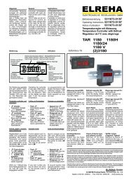
Wiring MiniMEP (2)404S, (2)424A<br />
ELREHA<br />
MiniMEP<br />
P<br />
1 2 3 4 5 6 7 8 9<br />
Mains phase 230V (US=115V)<br />
Mains neutral<br />
alrm relay N/C contact<br />
alarm relay N/O contact<br />
alarm relay common<br />
L/report input 1 (al1) mains ph.<br />
L/report input 2 (al2) mains ph.<br />
L/report input 3 (door) mains ph.<br />
PE<br />
- The terminals 10 and 11are valid<br />
only for MiniMEP's with option 'A'<br />
- Terminals 3 to 8 not available in<br />
type 404 S<br />
1 2 3 4 5 6 7 8 9<br />
Wiring the probes / sensors<br />
10 12 14 16 18 20 22 24<br />
11 13 15 17 19 21 23 25<br />
10 Accu +<br />
11 Accu -<br />
12 RS 485 NDO<br />
13 RS 485 DO<br />
14 Probe 1<br />
15 Probe 1 com.<br />
16 Probe 2<br />
17 Probe 2 com.<br />
18 Probe 3<br />
19 Probe 3 com.<br />
20 Probe 4<br />
21 Probe 4 com.<br />
22 n.c.<br />
23 RxD (RS 232)<br />
24 GND (RS 232)<br />
25 TxD (RS 232)<br />
10 12 14 16 18 20 22 24<br />
11 13 15 17 19 21 23 25<br />
Wiring MiniMEP 424/12V<br />
ELREHA<br />
MiniMEP<br />
P<br />
1 2 3 4 5 6 7 8 9<br />
Supply voltage +12V DC<br />
Supply voltage -12V DC<br />
alarm relay N/C contact<br />
alarm relay N/O contact<br />
alarm relay common<br />
report input 1 (al1) +12V DC<br />
report input 2 (al2) +12V DC<br />
report input 3 (door) +12V DC<br />
RS-232 Interface MiniMEP 4xx<br />
1 2 3 4 5<br />
connector SUB-D 9 male<br />
RS-232-interface connector<br />
6<br />
10 12 14 16 18 20 22 24<br />
11 13 15 17 19 21 23 25<br />
7 8 9<br />
10 n.c.<br />
11 n.c.<br />
12 RS 485 NDO<br />
13 RS 485 DO<br />
14 Probe 1<br />
15 Probe 1 com.<br />
16 Probe 2<br />
17 Probe 2 com.<br />
18 Probe 3<br />
19 Probe 3 com.<br />
20 Probe 4<br />
21 Probe 4 com.<br />
22 n.c.<br />
23 RxD (RS 232)<br />
24 GND (RS 232)<br />
25 TxD (RS 232)<br />
RxD (data in)<br />
TxD (data out)<br />
GND<br />
These ports are also connected to the screw<br />
terminals 23-25.<br />
They may not be connected at the same time
page 8<br />
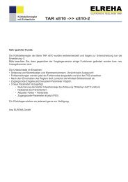
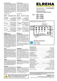
Wiring MiniMEP (2)434 A<br />
ELREHA<br />
MiniMEP<br />
P<br />
1 2 3 4 5 6 7 8 9<br />
mains phase<br />
mains neutral<br />
alarm relay N/C<br />
alarm relay N/O<br />
alarm relay common<br />
L/input 1 (al1) 230V<br />
L/input 2 (al2) 230V<br />
L/input 3 (door) 230V<br />
PE<br />
1 2 3 4 5 6 7 8 9<br />
don't remove<br />
external resitors !!<br />
If humidity transmitters are used,<br />
they must be supplied by an<br />
external AC adaptor.<br />
This example shows an SV 401<br />
adaptor supplying two FF 2520<br />
transmitters.<br />
don't remove external resistors !!<br />
10 12 14 16 18 20 22 24<br />
51R<br />
51R<br />
11 13 15 17 19 21 23 25<br />
10 12 14 16 18 20 22 24<br />
51R<br />
51R<br />
11 13 15 17 19 21 23 25<br />
10 accu +<br />
11 accu -<br />
12 RS 485 NDO<br />
13 RS 485 DO<br />
14 + input 1 4/20mA<br />
15 - input 1 4/20mA<br />
16 probe 2<br />
17 probe 2 com.<br />
18 + input 3 4/20mA<br />
19 - input 3 4/20mA<br />
20 probe 4<br />
21 probe 4 com.<br />
22 n.c.<br />
23 RxD (RS 232)<br />
24 GND (RS 232)<br />
25 TxD (RS 232)<br />
1 2 3 4 5 6<br />
~ 14V ~ +8V +20V GND<br />
ELREHA<br />
Netz<br />
SV 401<br />
~ ~<br />
A B<br />
+ 15-32VDC<br />
+ 4-20mA<br />
+ 0-10V<br />
Netz<br />
230V<br />
Technical Manual MiniMEP Data Loggers<br />
FF 2520 FF 2520<br />
+ 15-32VDC<br />
+ 4-20mA<br />
+ 0-10V
Technical Manual MiniMEP Data Loggers page 9<br />
Connections<br />
MiniMEP 5xx<br />
20 21 22 23 24<br />
MiniMEP 500<br />
Netzteil<br />
PE<br />
Netz N<br />
Netz L<br />
1 2<br />
3<br />
4<br />
5<br />
25 26 27 28 29 30 31<br />
6<br />
L/Eing. NK<br />
7<br />
L/Eing. TK<br />
8<br />
12V<br />
L/Tür<br />
9<br />
zum Bedienteil<br />
1 2 3 4 5 6 7 8 9 10 11 12 13 14 15 16 17 18 19<br />
Connection of humidity<br />
transmitters to a<br />
MiniMEP (2)534 A<br />
20 21 22 23 24<br />
MiniMEP 500<br />
Power Unit<br />
PE<br />
Mains N<br />
Mains Line<br />
1 2<br />
1 2<br />
3<br />
4<br />
5<br />
*<br />
32 33 34 35 36 37 38<br />
28 29 30 31 32 33 34 35 36 37 38<br />
25 26 27 28 29 30 31<br />
6<br />
L/Input 1<br />
L/Input 2<br />
L/door<br />
7<br />
8<br />
12V<br />
9<br />
to controller unit<br />
ELREHA<br />
3 4 5 6 7 8 9 10 11 12 13 14 15 16 17 18 19<br />
*<br />
32 33 34 35 36 37 38<br />
28 29 30 31 32 33 34 35 36 37 38<br />
ELREHA<br />
If humidity transmitters are used, they must be<br />
supplied by an external AC adaptor.<br />
This example shows an SV 401 adaptor supplying<br />
two FF 2520 transmitters.<br />
38<br />
37<br />
36<br />
35<br />
34<br />
33<br />
32<br />
31<br />
30<br />
F1<br />
F2<br />
F3<br />
10<br />
11<br />
12<br />
13<br />
14<br />
15<br />
16<br />
17<br />
Schirm nur an der Bediengerätseite auflegen<br />
F4<br />
RS232<br />
5<br />
4<br />
3<br />
2<br />
1<br />
9<br />
6 7 8<br />
RxD<br />
TxD<br />
GND<br />
NDO<br />
DO<br />
PE<br />
18<br />
19<br />
20<br />
21<br />
22<br />
23<br />
Terminals 28 and 29 are only valid for<br />
type 524 A.<br />
* Standard types (without "A") don't<br />
need the cables between terminals 37<br />
and 38.<br />
connected shielding at controller unit only<br />
38<br />
37<br />
36<br />
35<br />
34<br />
33<br />
32<br />
31<br />
30<br />
S1<br />
S2<br />
S3<br />
RS232<br />
10<br />
11<br />
12<br />
13<br />
14<br />
15<br />
16<br />
17<br />
18<br />
19<br />
20<br />
21<br />
22<br />
23<br />
S4<br />
5<br />
4<br />
3<br />
2<br />
1<br />
9<br />
6 7 8<br />
RxD<br />
TxD<br />
GND<br />
NDO<br />
DO<br />
PE<br />
FF 2520<br />
+ 15-32VDC<br />
+ 4-20mA<br />
+ 0-10V<br />
RS-232-interface connector<br />
1 2 3 4 5<br />
6 7 8 9<br />
RxD (data in)<br />
TxD (data out)<br />
GND<br />
Stecker SUB-D 9-polig male<br />
These ports are also<br />
connected to the screw<br />
terminals 18-20.<br />
They may not be connected<br />
at the same time<br />
1 2 3 4 5 6<br />
~ 14V ~ +8V +20V GND<br />
ELREHA<br />
Netz<br />
FF 2520<br />
SV 401<br />
+ 4-20mA<br />
+ 0-10V<br />
Netz<br />
230V<br />
~ ~<br />
A B<br />
+ 15-32VDC
page 10<br />
Dimensions of MiniMEP 4xx types<br />
186 (7.32)<br />
Dimensions/Terminals of MiniMEP (2)524 A, (2)534 A Operating Unit<br />
ELREHA<br />
131 (5.16)<br />
P<br />
96<br />
MiniMEP<br />
Dimensions/Terminals of MiniMEP (2)524 A, (2)534 A Power Unit<br />
20 21 22 23 24<br />
MiniMEP 500<br />
Netzteil<br />
PE<br />
Netz N<br />
Netz L<br />
1 2<br />
3<br />
4<br />
ELREHA<br />
5<br />
25 26 27 28 29 30 31<br />
6<br />
160 (6.3)<br />
130 (5.12)<br />
L/Eing. 1 NK<br />
L/Eing. 2 TK<br />
7<br />
8<br />
MiniMEP<br />
P<br />
12V<br />
96<br />
9<br />
105<br />
32 33 34 35 36 37 38<br />
zum Bedienteil<br />
28 29 30 31 32 33 34 35 36 37 38<br />
L/Ein. 3<br />
Tür<br />
89,5<br />
5 4 3 2 1<br />
9 8 7 6<br />
ELREHA<br />
1 2 3 4 5 6 7 8 9 10 11 12 13 14 15 16 17 18 19<br />
72,5<br />
63<br />
47<br />
63<br />
93<br />
145 (5.71)<br />
10 (.39)<br />
8<br />
60 (2.36)<br />
F1<br />
Technical Manual MiniMEP Data Loggers<br />
105 (4.13)<br />
Verbindungen zum Netzteil<br />
10<br />
38<br />
11<br />
37<br />
12<br />
36<br />
13<br />
35<br />
14<br />
34<br />
15<br />
33<br />
16<br />
32<br />
17 31<br />
18 RxD 30<br />
F2<br />
F3<br />
59<br />
39<br />
26<br />
F4<br />
35<br />
RS232<br />
4 5<br />
3<br />
2<br />
1<br />
9<br />
8<br />
7<br />
6<br />
TxD<br />
GND<br />
NDO<br />
DO<br />
PE<br />
19<br />
20<br />
21<br />
22<br />
23
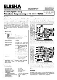
Technical Manual MiniMEP Data Loggers page 11<br />
Processing of recorded data / Unlock unit for use with PC-Software<br />
The values recorded by the MiniMEP can be retrieved via its<br />
interfaces and processed by PC-Software. Here are the most<br />
important szenarios in practise:<br />
• Networking together with other controllers<br />
The MiniMEP is connected to a controller network via its RS-<br />
485-interface which allows remote access from a host. In<br />
this case, each unit on the bus gets an individual address<br />
within 1 and 78 (Parameter 'address' on parameter page).<br />
• Direct PC connection<br />
As a low cost alternative for a serial printer, a PC can be<br />
connected to the RS-232-interface.<br />
• Direct PC connection of several MiniMEP<br />
Electrical connection must be done as described above via<br />
RS-485 interface. The PC must be equipped with an RS-485interface,<br />
or an Interface Converter of the series SSC must be<br />
used.<br />
Connection of several MiniMEP / controller units via RS-485 interface and SSC converter<br />
+ � � �L EI E� �<br />
� @ A H<br />
+ 8 �5 ? D A @ K �A H<br />
COM-interface<br />
(used cable is<br />
"PC-SSC/SUB-D")<br />
Interface Converter<br />
SSC 8022<br />
DO<br />
RS-232<br />
Connection of a single MiniMEP via RS-232 interface<br />
+ � � �L EI E� �<br />
� @ A H<br />
+ 8 �5 ? D A @ K �A H<br />
COM-interface<br />
(used cable is<br />
"PC-SSC/SUB-D")<br />
GND<br />
NDO<br />
1<br />
6<br />
+13V<br />
9 pole<br />
female<br />
Connection of a single MiniMEP to a PC with USB interface<br />
+ � � � 8 EI E� � � @ A H<br />
+ 8 �5 ? D A @ K �A H<br />
USB converter<br />
USB001<br />
9<br />
8<br />
7<br />
6<br />
5<br />
4<br />
3<br />
2<br />
1<br />
9 pole<br />
female<br />
9<br />
8<br />
7<br />
6<br />
5<br />
4<br />
3<br />
2<br />
1<br />
(used cable is<br />
"PC-SSC/SUB-D")<br />
Gnd<br />
out<br />
in<br />
Gnd<br />
out<br />
in<br />
PC-Software<br />
If the MiniMEP is connected to controller network, the software<br />
"COOLVision" is used normally. If a PC should operate with one<br />
or more MiniMEP exclusively, the software "CV-Scheduler" is<br />
recommended.<br />
9 pole<br />
female<br />
5<br />
9<br />
4<br />
8 3<br />
7 2<br />
6<br />
8<br />
7<br />
6<br />
Unlock unit for use with PC-Software "CV-Scheduler"<br />
If a MiniMEP is intended to operate with software "CV-<br />
Scheduler", an unlock code must be entered while startup.<br />
You get this unlock code with the software, please see<br />
software manual for further information.<br />
Without this code, retrieve and processing of data with the<br />
software is impossible.<br />
How to check if your MiniMEP is unlocked for CV-Scheduler<br />
software:<br />
- Access parameter page,<br />
- Select parameter 'software',<br />
- If the unit is unlocked, you will find the additional info<br />
"pro" behind the software version.<br />
1<br />
9 pole<br />
female<br />
9<br />
5<br />
4<br />
3<br />
2<br />
1<br />
GND DO NDO GND DO NDO<br />
MiniMEP MiniMEP<br />
or<br />
other<br />
controller<br />
PE PE<br />
GND (alternative terminal 24)<br />
TxD (alternative terminal 25)<br />
RxD (alternative terminal 23)<br />
MiniMEP 4xx<br />
GND (alternative terminal 24)<br />
TxD (alternative terminal 25)<br />
RxD (alternative terminal 23)<br />
MiniMEP 4xx<br />
Electrical<br />
Cabinet
page 12<br />
Sensor - Installation<br />
Temperature Sensors<br />
With the three offered sensor types TF 501 5M, TF 501 10M and<br />
TF 501 15M the MiniMEP is able to work within the specified<br />
accuracy range.<br />
Attention !<br />
TF 501 sensor versions are specified up to 80°C only.<br />
To measure higher temperatures, please use another<br />
sensor type.<br />
Cable length<br />
The cable can be shortened every time, if it must be extended<br />
please note the following:<br />
� If the resistance of the additional terminal is less than<br />
0,1 ohms, you can extend with a shielded cable type as<br />
shown in this table.<br />
cable diameter 0,5mm² 1mm² 1,5mm²<br />
TF 501/5M < 20m < 40m < 60m<br />
TF 501/10M < 15m < 30m < 45m<br />
TF 501/15M < 10m < 20m < 30m<br />
Accu - Operation<br />
The MiniMEP types (2)424 A, (2)524 A and (2)534 A are equipped<br />
with terminals for an external Lead Accu. The integrated charge<br />
controller cares for a slow but sparing charge of the accu while<br />
the MiniMEP works with mains voltage.<br />
Start-up<br />
Notes:<br />
• Connect accu first, if the MiniMEP is ready for<br />
operation with mains voltage.<br />
• To prevent the accu from deep-discharge,<br />
disconnect accu or switch ON the MiniMEP with<br />
mains voltage if the unit has been shut-down by<br />
the charge monitoring function after some hours<br />
of accu-operation.<br />
• Charge process may last up to some days.<br />
When voltage is applied to the controller, date, current time and<br />
actual sensor input 1 value is displayed.<br />
By pressing any key the displays backlight turns on.<br />
� Switch ON the needed sensor inputs on parameter page<br />
� Check the displayed temperatures refering to a calibrated<br />
thermometer at the position of the sensor. Register the<br />
results on the start-up checklist ('Prüfprotokoll', section 2).<br />
� Select storage interval (parameter 'recording')<br />
� If desired, you may fix a name for each sensor or digital<br />
input (see page 3).<br />
� Set the parameters of the additional functions now, if they<br />
are necessary.<br />
CONNECTION & SAFETY INFORMATION<br />
Technical Manual MiniMEP Data Loggers<br />
The guarantee will lapse in case of damage caused by failure<br />
to comply with these operating instructions! We shall not be<br />
liable for any consequent loss! We do not accept liability for<br />
personal injury or damage to property caused by inadequate<br />
handling or non-observance of the safety instructions! The<br />
guarantee will lapse in such cases. Servicing or repair work<br />
may only be carried out by a specialist workshop.<br />
• Limit of Application: This product is not designed nor<br />
manufactured for use in equipment or systems that are<br />
intended to be used under such circumstances that may<br />
affect human life. For applications requiring extremely<br />
high reliability, please contact the manufacturer first.<br />
• Electrical installation and putting into service must be<br />
done from authorized personnel.<br />
• Please note the local safety instructions !<br />
• Before installation: Check the limits of the unit and your<br />
application. Before starting up we recommend you to<br />
read the manual for use, since only by doing so you can<br />
avoid damage or malfunction and you will benefit all the<br />
advantages offered by this product.<br />
• During installation and wiring never work when the<br />
electricity is not cut-off !<br />
• Mounting the unit close to power relays is unfavourable in<br />
case of the electro-magnetic interference.<br />
• Before applying voltage to the unit:<br />
Make sure that all wiring has been made in accordance<br />
with the wiring diagram in this manual.<br />
Check, if the supply voltage corresponds to the value<br />
printed on the type label.<br />
• Connect ‘PE’ terminal carefully to ground, otherwise the<br />
internal noise filter will not work.<br />
• Respect the environmental limits for temperature and<br />
humidity. Outside these limits malfunctions may occur.<br />
• Never operate unit without housing.<br />
• For sensor cables, use shielded types only. Don’t install<br />
them in parallel with high-current cables to prevent<br />
inductive interference.<br />
• TF-type sensors are are not designed for being immersed<br />
in water for a long period of time (not pressure-proof). In<br />
such a case, always use dip-fittings.<br />
• Take care that the wiring of interface lines meets the<br />
requirements<br />
Please note the rule EN 13486, which describes<br />
the responsibility of the user for calibration of<br />
the unit at regular intervals.
Technical Manual MiniMEP Data Loggers page 13<br />
Technical Data<br />
Unit is suitable for storage (S), ambient conditions (A),<br />
accuracy level (1)<br />
Supply voltage ................... 230V / 50-60Hz<br />
US-versions (2)xxx ......... 115V / 60Hz<br />
Version 424/12V ............ 12V DC<br />
Power consumption ........... app. 5VA max.<br />
Ambient temperature ......... 0...+50°C (32...+122°F)<br />
Inputs ................................. max. 4 x TF 501<br />
Inputs MiniMEP x34 A ....... 2x 4...20mA, 2x TF 501<br />
Digital- (Report-) inputs ..... 3x mains phase with adjustable<br />
name and time delay<br />
Version 424/12V ............ 3x +12V DC<br />
Calibration ......................... factory set, maintenance free<br />
Display resolution .............. -160...+60°C = 0,1K<br />
-256...+140°F = 0,2°F<br />
Protocol resolution............. -110...-50°C = 0,5K<br />
-50...+100°C = 0,1K<br />
+100...+150°C = 0,5K<br />
+150...+300°C = 1,0K<br />
+300...+600°C = 2,0K<br />
-166...-58°F = 1°F<br />
-58...+212°F = 0,2°F<br />
+212...+302°F = 1°F<br />
+302...+572°F = 1,8°F<br />
+572...+1112°F = 3,6°F<br />
0...100% = 0,1%<br />
Storage intervals ............... 1/2/3/4/5/6/10/12/15/20/30/60 min.<br />
Outputs .............................. Buzzer, 1x alarm relay (SPDT),<br />
isolated, 4A / cos phi=1/250V<br />
Interfaces ........................... RS 232, RS 485<br />
Accu interface .................... Charge controller for 1,3 Ah Lead Accus<br />
(not types 404 S, 2404 S, 424/12V)<br />
Data memory ..................... see type overview<br />
Real time clock .................. automatic summer/winter shift,<br />
can be disabled<br />
Data storage ...................... unlimited, clock backup typ. 10 years<br />
Housing<br />
4xx-types ........................ plastic, wall mounting, IP 54<br />
5xx-types ........................ plastic, panel mounting,<br />
IP 54 from front<br />
Supplied accessories (2)4xx types<br />
� This manual<br />
� 1 x Fitting PG 9<br />
� 1 x Fitting PG 11<br />
� 1 x Fitting PG 13,5<br />
� 3 x Screws 4 x 40<br />
� 3 x Dowels 6mm<br />
Not supplied accessories<br />
Temperature Sensors<br />
� TF 501/5M, diam. 6 mm, 5 meters shielded cable<br />
TF 501/10M, diam. 6 mm, 10 meters shielded cable<br />
TF 501/15M, diam. 6 mm, 15 meters shielded cable<br />
Attention! only suitable up to 80°C !<br />
Humidity Sensors<br />
� FF 2520, humidity transmitter with 4/20mA output, must be<br />
supplied by an external AC-adaptor.<br />
Please note installation information !<br />
� MiniMEP PC-software "CV-Scheduler"<br />
� External Accumulator or Accu-set<br />
� PC-cable (see text)
page 14<br />
(copy)<br />
EG-Statement of Conformity<br />
Technical Manual MiniMEP Data Loggers<br />
We state the following: When operated in accordance with the technical manual, the criteria have been met that are outlined in<br />
the guidelines of the council for alignment of statutory orders of the member states on electro-magnetic consistency (89/336/EWG) and the Low Voltage<br />
Directive (73/23/EWG) as amended by (93/68/EWG). This declaration is valid for those products covered by the technical manual which itself is part of<br />
the declaration. To meet the requirements, the currently valid versions of the relevant standards have been used.<br />
This statement is made from the manufacturer / importer by:<br />
ELREHA Elektronische Regelungen GmbH<br />
D-68766 Hockenheim, Germany<br />
Werner Roemer, Technical Director<br />
www.elreha.de Hockenheim.............12.09.2005......................................................<br />
(name / adress) city date sign<br />
This manual has been set up with care and to our best knowledge, but mistakes are still possible. Technical details, especially the software, can<br />
be changed without notice. Please note that this manual is only valid for controllers containing the software-version shown on page 1. This versionnumber<br />
is also displayed in the parameter page. If you have still problems or difficulties or questions please don´t hesitate asking our technical<br />
support. Called trademarks are properties of their companies.<br />
Set up : 17.5.06, tkd/jr checked: 18.5.06, ek/jk approved: 18.5.06, mv/sha
Drilling template MiniMEP x422 / x424<br />
Maßstab 1:1<br />
scale 1:1<br />
Bohrer/Drill Ø 6mm (.24)<br />
7mm (.27)<br />
116mm (4.57)<br />
Bohrer/Drill Ø 6mm (.24)<br />
65mm (2.56)<br />
155 (6.1)<br />
11<br />
(.43)<br />
163,5 (6.42)