Sea-Doo 4-TEC Open Loop Cooling Kit - GreenHulk Personal ...
Sea-Doo 4-TEC Open Loop Cooling Kit - GreenHulk Personal ...
Sea-Doo 4-TEC Open Loop Cooling Kit - GreenHulk Personal ...

Create successful ePaper yourself
Turn your PDF publications into a flip-book with our unique Google optimized e-Paper software.
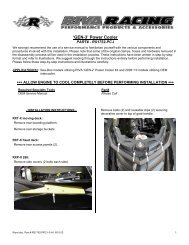
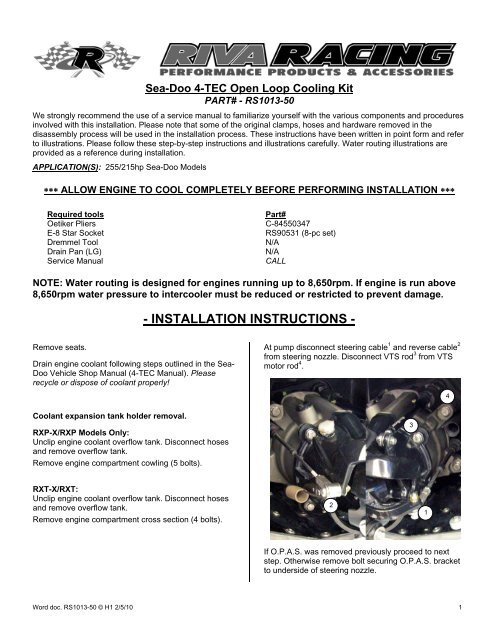
<strong>Sea</strong>-<strong>Doo</strong> 4-<strong>TEC</strong> <strong>Open</strong> <strong>Loop</strong> <strong>Cooling</strong> <strong>Kit</strong><br />
PART# - RS1013-50<br />
We strongly recommend the use of a service manual to familiarize yourself with the various components and procedures<br />
involved with this installation. Please note that some of the original clamps, hoses and hardware removed in the<br />
disassembly process will be used in the installation process. These instructions have been written in point form and refer<br />
to illustrations. Please follow these step-by-step instructions and illustrations carefully. Water routing illustrations are<br />
provided as a reference during installation.<br />
APPLICATION(S): 255/215hp <strong>Sea</strong>-<strong>Doo</strong> Models<br />
∗∗∗ ALLOW ENGINE TO COOL COMPLETELY BEFORE PERFORMING INSTALLATION ∗∗∗<br />
Required tools<br />
Part#<br />
Oetiker Pliers C-84550347<br />
E-8 Star Socket RS90531 (8-pc set)<br />
Dremmel Tool<br />
N/A<br />
Drain Pan (LG)<br />
N/A<br />
Service Manual<br />
CALL<br />
NOTE: Water routing is designed for engines running up to 8,650rpm. If engine is run above<br />
8,650rpm water pressure to intercooler must be reduced or restricted to prevent damage.<br />
- INSTALLATION INSTRUCTIONS -<br />
Remove seats.<br />
Drain engine coolant following steps outlined in the <strong>Sea</strong>-<br />
<strong>Doo</strong> Vehicle Shop Manual (4-<strong>TEC</strong> Manual). Please<br />
recycle or dispose of coolant properly!<br />
Coolant expansion tank holder removal.<br />
RXP-X/RXP Models Only:<br />
Unclip engine coolant overflow tank. Disconnect hoses<br />
and remove overflow tank.<br />
Remove engine compartment cowling (5 bolts).<br />
At pump disconnect steering cable 1 and reverse cable 2<br />
from steering nozzle. Disconnect VTS rod 3 from VTS<br />
motor rod 4 .<br />
3<br />
4<br />
RXT-X/RXT:<br />
Unclip engine coolant overflow tank. Disconnect hoses<br />
and remove overflow tank.<br />
Remove engine compartment cross section (4 bolts).<br />
2<br />
1<br />
If O.P.A.S. was removed previously proceed to next<br />
step. Otherwise remove bolt securing O.P.A.S. bracket<br />
to underside of steering nozzle.<br />
Word doc. RS1013-50 © H1 2/5/10 1
Remove bolts (4) securing pump assembly to hull.<br />
Remove pump assembly.<br />
Disconnect hoses (6) connected to thermostat housing.<br />
Completely remove all hoses except for the two<br />
connected to oil cooler (#’s 3 & 5).<br />
Remove rubber boot sealing VTS motor shaft. Remove<br />
nut securing VTS motor unit to hull.<br />
If a RIVA Performance Ride Plate will be installed<br />
proceed to next step. Otherwise, install supplied vinyl<br />
caps over stock ride plate fittings and secure using<br />
supplied zip ties.<br />
If using a RIVA Pro-Series Water Box proceed to next<br />
step. Otherwise remove exhaust tube between water<br />
box and thru-hull outlet.<br />
Remove intercooler air inlet and outlet tubes.<br />
Install the supplied sacrificial zinc anode into the<br />
supplied billet water pump cover.<br />
Loosen the four bolts securing throttle body to intake<br />
manifold. Remove throttle body and move forward in<br />
engine compartment.<br />
Remove the two bolts securing front of RIVA Power<br />
Filter tube to engine bracket. This will allow you to move<br />
Power Filter tube as needed during installation process.<br />
Inside hull remove VTS motor unit from thru-hull fitting<br />
and move forward in engine compartment.<br />
Word doc. RS1013-50 © H1 2/5/10 2
Remove bolts (8) securing thermostat housing to<br />
engine. Remove thermostat housing from engine.<br />
Install supplied thermostat unit onto rear of cylinder<br />
head. Secure using the supplied 47.0 Oetiker.<br />
2<br />
1<br />
4<br />
3<br />
8<br />
5<br />
7<br />
NOTE: Do not remove impeller from engine.<br />
Transfer o-ring from back of thermostat housing to back<br />
of supplied billet water pump cover.<br />
6<br />
Apply a thin coat of grease to o-ring. Install billet water<br />
pump cover onto engine and secure using OE bolts.<br />
Torque to 89 lbf•in / 10 N•m. NOTE: Apply r Loc-tite to<br />
bolts.<br />
At rear of cylinder head remove the barbed brass fitting<br />
for coolant overflow hose. Install supplied stainless steel<br />
block-off screw.<br />
<strong>Cooling</strong> Line Removal:<br />
255hp Models Only: Locate and completely remove<br />
cooling lines with ‘T’ fitting coming in from transom to<br />
intercooler and exhaust manifold 1 as well as cooling<br />
lines with ‘T’ fitting going to transom from exhaust<br />
manifold and intercooler 2 .<br />
2<br />
NOTE: Apply pipe thread sealant to threads. Tighten screw until<br />
head is flush with cylinder head.<br />
1<br />
Word doc. RS1013-50 © H1 2/5/10 3
215hp Models Only: Locate and completely remove<br />
the cooling lines from transom to intercooler and from<br />
intercooler to exhaust manifold.<br />
Locate and remove 3/8” waterline between top of ‘J’<br />
pipe and transom 1 .<br />
1<br />
2<br />
3<br />
1<br />
Route open end (14” length 3 ) towards intercooler<br />
support bracket.<br />
Install supplied 3/4” bypass fitting.<br />
Install supplied 3/4” cooling line assembly (labeled ‘B’).<br />
Attach 24” length 1 to transom inlet fitting. Route 12”<br />
length 2 towards intercooler. Route flush kit 3 so it can be<br />
secured in an accessible location.<br />
2<br />
1<br />
3<br />
NOTE: Enough cooling line is provided so that bypass can be<br />
installed in transom near rear exhaust outlet. However, bypass<br />
can be installed in pump transom tunnel if desired.<br />
Attach 3/4” cooling lines to intercooler. Secure with<br />
stock hose clamps.<br />
Install supplied 3/4” cooling line assembly (labeled ‘A’)<br />
between the intercooler and motor. The 15” length 1<br />
attaches to billet water pump cover. Secure with stock<br />
hose clamp. The 33” length 2 attaches to fitting at front of<br />
exhaust manifold (route under drive shaft and motor).<br />
Secure with stock hose clamp.<br />
2<br />
1<br />
1- Line in to intercooler from transom/flush kit.<br />
2- Line out from intercooler to motor.<br />
Word doc. RS1013-50 © H1 2/5/10 4
Install the supplied 36” length of 1/2” waterline to the<br />
upper cooling line 3 (oil cooler inlet line). Secure using<br />
supplied 21.0 Oetiker.<br />
1<br />
2<br />
3<br />
3- Line in to intercooler from transom/flush kit.<br />
4- Line out from intercooler to motor.<br />
Replace intercooler and secure to support bracket.<br />
On right side of engine cut oil cooler lines just before<br />
support bracket 1 . Install supplied 1/2” x 5/8” brass hose<br />
splicer into each hose and secure using supplied 25.6<br />
Oetikers.<br />
Route waterline under drive shaft and towards exhaust<br />
pipe/water box joint.<br />
Attach to applicable fitting (see below) and secure using<br />
stock hose clamp. Trim excess as needed.<br />
1<br />
NOTE: Larger end of splicer goes into oil cooler hose.<br />
Install supplied 24” length of 1/2” waterline between<br />
lower cooling line 1 (oil cooler outlet line) and 3/8”<br />
transom fitting 2 . Secure to oil cooler line using supplied<br />
21.0 Oetiker. Secure to transom fitting using stock<br />
clamp.<br />
`08 & newer attach to fitting under end of exhaust manifold.<br />
1<br />
2<br />
`07 & older attach to fitting at top of ‘J’ pipe (trim excess as<br />
needed). Secure using stock hose clamp.<br />
Word doc. RS1013-50 © H1 2/5/10 5
Replace VTS motor unit into thru-hull fitting making sure<br />
rubber grommet at bottom of housing is installed onto<br />
VTS mounting bracket.<br />
At rear of craft in pump area replace and secure VTS<br />
motor nut. Replace and secure rubber boot sealing VTS<br />
motor shaft. NOTE: Do not over tighten nut.<br />
If using a stock water box replace exhaust outlet tube.<br />
NOTE: Do not over tighten clamps.<br />
At rear of craft in pump area replace OE water inlet<br />
reducer with supplied reducer.<br />
Replace Power Filter Tube. NOTE: Apply blue Loc-tite<br />
to bolts. Do not over tighten bolts. Do not over<br />
tighten clamps.<br />
Replace throttle body and secure using OE bolts.<br />
NOTE: Torque bolts to 11 N•m (97 lbf•in) in a crisscross<br />
pattern.<br />
Install 36” length of supplied 3/4” cooling line between<br />
thermostat on cylinder head and 3/4” bypass fitting in<br />
hull. Trim excess as needed. Secure to thermostat<br />
using supplied 30.1 Oetiker. Secure to 3/4” bypass<br />
using stock hose clamp.<br />
NOTE: Supplied water reducer has a larger I.D. and is stamped<br />
with an ‘X’ on one side.<br />
If a RIVA Performance Ride Plate will be installed<br />
continue with the instructions included with ride plate.<br />
Otherwise, apply glass cleaner to rubber seal on pump<br />
assembly. Install pump into craft and secure using<br />
supplied bolts. NOTE: Apply blue Loc-tite to bolts.<br />
Torque to 31 N•m (23 lbf•ft) in a criss-cross pattern.<br />
Reconnect VTS rod, reverse cable and steering cable.<br />
NOTE: Do not over tighten bolts.<br />
If O.P.A.S. was removed proceed to next step.<br />
Otherwise, reconnect O.P.A.S. bracket to steering<br />
nozzle. NOTE: Use blue Loc-Tite. Torque bolt to 25<br />
N•m (18 lbf•ft).<br />
RXP-X/RXP Models Only:<br />
Replace engine compartment cowling (5 bolts).<br />
Replace supercharger air inlet components. NOTE: Do<br />
not over tighten bolts.<br />
Replace intercooler air inlet and outlet tubes. NOTE: Do<br />
not over tighten bolts.<br />
RXT-X/RXT:<br />
Replace engine compartment cross section (4 bolts).<br />
Check bilge for tools, rags, etc. Run craft on flush kit to<br />
check for leaks and to ensure smooth operation.<br />
Word doc. RS1013-50 © H1 2/5/10 6
IMPORTANT MAINTENANCE INFORMATION<br />
Flushing: To assure optimal performance with this kit extra care must be used with flushing. The <strong>Open</strong> <strong>Loop</strong> flush<br />
connector will be used in place of the stock flush kit fitting in the pump. We strongly recommend the use of a salt<br />
/deposit remover such as Salt-Away® which can be purchased through RIVA Racing’s parts department. When flushing<br />
with a salt/deposit remover do not flush with fresh water afterwards. Allow salt/deposit remover to remain in cooling<br />
system. This will prevent build up of salt or deposits from residual water in cooling system. At the end of your riding<br />
season we recommend “winterizing” your craft if you are unable to ride for an extended period of time.<br />
Sacrificial Anode: <strong>Open</strong> <strong>Loop</strong> <strong>Cooling</strong> <strong>Kit</strong> water pump cover is equipped with a sacrificial anode. This is to prevent<br />
corrosion from occurring in the motor should you “forget” to flush your craft. However, it is not intended to be used as an<br />
alternative to flushing your craft. Anode will deteriorate over time and should be replaced each season or as needed.<br />
Check anode at beginning and end of riding season. When replacing apply pipe thread sealant to threads and do not<br />
over tighten. Replacement anodes are available through RIVA Racing’s parts department.<br />
Remember, the water belongs to everyone.<br />
Please ride responsibly and respect the environment!<br />
Technical Support<br />
For answers to questions regarding installation or trouble shooting RIVA Performance Products contact:<br />
RIVA Technical Support directly at (954) 247-0705 or by e-mail at tech_support@rivamotorsports.com.<br />
Limited Warranty<br />
RIVA <strong>Open</strong> <strong>Loop</strong> <strong>Cooling</strong> <strong>Kit</strong>s carry a 1-year limited warranty to the original purchaser. They are warranted to be free of defects in materials and workmanship under normal<br />
use and service. Customer modified components will be void of warranty. This warranty is limited to defects in the primary components only. Finish and/or wear marks in or<br />
on primary components are not covered under this warranty.<br />
RIVA Racing’s liability is expressly limited to the repair or replacement of the components contained within or associated with this kit. RIVA Racing agrees to repair or at<br />
RIVA’s option, replace any defective unit without charge, if product is returned to RIVA Racing freight prepaid within the warranty period. Any equipment returned which, in<br />
RIVA’s opinion, has been subjected to misuse, abuse, overheating or accident shall not be covered by this warranty.<br />
RIVA Racing shall have no liability for special, incidental or consequential damages or injury to persons or property from any cause arising from the sale, installation or use<br />
of this product.<br />
No other warranty, express or implied, including, but not limited to the implied warranties of merchantability and fitness for a particular purpose, applies. Various states do<br />
not allow for the limitation of incidental or consequential damages and therefore the above exclusion or limitation may not apply to you.<br />
Warranty does not include the expenses related to freight or transportation of parts or compensation for any inconvenience or loss of use while being repaired. A copy of<br />
the original invoice and a Return Authorization Number (RA#) must accompany all warranty claims.<br />
Warranted replacement parts will be returned freight collect.<br />
Word doc. RS1013-50 © H1 3/25/10 7
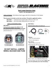
255hp Intercooler Upgrade <strong>Kit</strong> & 215hp GEN-2 Power Cooler <strong>Kit</strong><br />
Water Routing Illustration<br />
PUMP / TRANSOM<br />
Supplied 3/4"<br />
Bypass Fitting<br />
3/4"0.D. x 24" L<br />
3/4"0.D. x 24" L<br />
GEN-2<br />
INTERCOOLER<br />
1/2"0.D. x 24" L<br />
1/2"0.D. x 32" L<br />
3/4"0.D. x 36" L<br />
WATER PUMP<br />
COVER<br />
WATER<br />
OUTLET<br />
OIL COOLER<br />
INTAKE MANIFOLD<br />
CYLINDER HEAD<br />
3/4"0.D. x 15" L<br />
COOLING<br />
LINE 'A'<br />
3/4"0.D. x 42" L<br />
3/4"0.D. x 12" L<br />
3/4"0.D. x 33" L<br />
3/4"0.D. x 16" L<br />
COOLING<br />
LINE 'B'<br />
31.0<br />
FLUSH KIT<br />
FITTING<br />
21.0<br />
THERMOSTAT<br />
UNIT<br />
47.0<br />
25.6<br />
25.6<br />
21.0<br />
3/4"0.D. x 33" L<br />
EXHAUST MANIFOLD<br />
= Supplied Oetiker Clamp<br />
= OE Hose Clamp<br />
= Supplied Barbed Hose Splicer
215hp GEN-1 Power Cooler <strong>Kit</strong><br />
Water Routing Illustration<br />
Supplied 3/4"<br />
Bypass Fitting<br />
PUMP / TRANSOM<br />
GEN-1<br />
INTERCOOLER<br />
3/4"0.D. x 24" L<br />
3/4"0.D. x 24" L<br />
3/4"0.D. x 16" L<br />
'J' Pipe<br />
1/2"0.D. x 12" L<br />
3/4"0.D. x 42" L<br />
COOLING<br />
LINE 'B'<br />
FLUSH KIT<br />
FITTING<br />
3/4"0.D. x 33" L<br />
1/2"0.D. x 24" L<br />
1/2"0.D. x 36" L<br />
3/4"0.D. x 15" L<br />
COOLING<br />
LINE 'A'<br />
31.0<br />
21.0<br />
THERMOSTAT<br />
UNIT<br />
WATER PUMP<br />
COVER<br />
47.0<br />
25.6<br />
WATER<br />
OUTLET<br />
OIL COOLER<br />
INTAKE MANIFOLD<br />
CYLINDER HEAD<br />
25.6<br />
21.0<br />
3/4"0.D. x 33" L<br />
EXHAUST MANIFOLD<br />
= Supplied Oetiker Clamp<br />
= OE Hose Clamp<br />
= Supplied Barbed Hose Splicer