ANGLgear® - Andantex USA Inc.
ANGLgear® - Andantex USA Inc.
ANGLgear® - Andantex USA Inc.

Create successful ePaper yourself
Turn your PDF publications into a flip-book with our unique Google optimized e-Paper software.
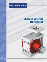
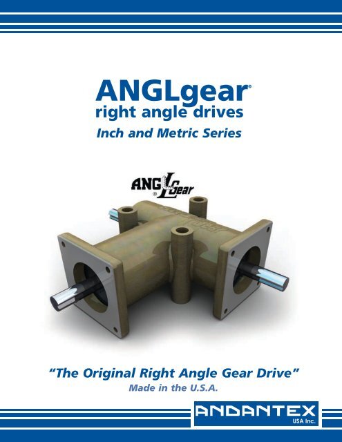
<strong>ANGLgear®</strong><br />
right angle drives<br />
<strong>Inc</strong>h and Metric Series<br />
“The Original Right Angle Gear Drive”<br />
Made in the U.S.A.
INDEX<br />
Intro to ANGLgear <strong>Inc</strong>h & Metric Series pg. 2-3<br />
2 Flange Units, <strong>Inc</strong>h Series pg. 4<br />
3 Flange Units, <strong>Inc</strong>h Series pg. 5<br />
Selection & Ordering Information, <strong>Inc</strong>h Series pg. 6<br />
2 Flange Units, Metric Series pg. 7<br />
3 Flange Units, Metric Series pg. 8<br />
Selection & Ordering Information, Metric Series pg. 9<br />
Special Units <strong>Inc</strong>h & Metric Series pg. 10<br />
1<br />
800-713-6170 • www.andantex.com • info@andantex.com
INTRODUCTION<br />
The Original Right-Angle Gear Drive<br />
The ANGLgear line of bevel gearboxes has proven its<br />
performance for over 40 years. It was developed to<br />
provide manual or power transmission of rotary motion in<br />
a compact, standardized right-angle unit. Each ANGLgear<br />
is manufactured at our factory in Wanamassa, NJ, <strong>USA</strong>.<br />
All units are inspected and tested to ensure proper<br />
operation at the rated speeds.<br />
The ANGLgear name is widely recognized and the product<br />
is in use worldwide. We also offer a line of metric<br />
ANGLgears for use in designs needing metric shaft<br />
diameters and mounting surfaces.<br />
Utilizing carburized case-hardened Coniflex* bevel gears,<br />
all ANGLgear units employ completely enclosed and<br />
sealed ball bearings and are lubricated for life. The cast<br />
aluminum housings are precision machined, and use<br />
flanged ends and side bosses for compact installation in a<br />
wide range of applications.<br />
Special and/or modified units are our specialty! At<br />
<strong>Andantex</strong> <strong>USA</strong>, we will modify our standard designs to fit<br />
your design specifications. For more information about our<br />
special gearboxes, refer to page 10 or consult the factory.<br />
Our Sales and Engineering departments are ready to help<br />
you with your specific application requirements.<br />
*Trademark – The Gleason Works, Rochester, NY<br />
ANGLgear Quality Specifications for both<br />
<strong>Inc</strong>h and Metric Series:<br />
Every ANGLgear manufactured is tested to meet our<br />
quality specifications and are 100% inspected prior to<br />
packaging. This process ensures a consistent quality of<br />
our gearboxes, and filters out units that might become a<br />
problem if installed in an application.<br />
NOISE LEVEL<br />
Experience has proven that noise level testing and<br />
inspection provide an accurate indication of operational<br />
efficiency. All ANGLgear units are tested to meet the<br />
following maximum noise levels for acceptance:<br />
Size 1 – R3000/R3003: 73 dB<br />
R3100/R3103: 74 dB<br />
Size 2 – R3200/R3203: 77 dB<br />
R3300/R3303: 78 dB<br />
Size 3 – R3330/R3350: 89 dB<br />
BACKLASH<br />
Each unit is checked for its gear mesh backlash to<br />
ensure it is within the prescribed backlash range. For<br />
Size 1, the backlash range is 1/4° to 3/4°. For Sizes 2<br />
through 5, the backlash is 1/8° to 1/2°. For special<br />
applications requiring reduced backlash, please consult<br />
the factory.<br />
MILITARY SPECIFICATIONS<br />
<strong>Andantex</strong> <strong>USA</strong> meets MIL-I-45208A for Inspection<br />
System Requirements. We can conform to military<br />
contracts specifying various MIL-SPEC requirements.<br />
LUBRICATION<br />
ANGLgear units are lubricated for life. All models are<br />
lubricated with Exxon Beacon 325 grease, having an<br />
operating temperature range from -65°F to +200°F<br />
(-54°C to +93°C). Different greases can be supplied<br />
upon request.<br />
Size 4 – R3400/R3500: 89 dB<br />
Size 5 – R3570/R3590: 89 dB<br />
For special applications requiring reduced noise levels,<br />
please consult the factory.<br />
800-713-6170 • www.andantex.com • info@andantex.com<br />
2
ANGLgear Quality Specifications:<br />
BEVEL GEARS<br />
All gears in the ANGLgear product line are cut using the<br />
Gleason Generating System to a AGMA Quality Class 9.<br />
This system develops straight bevel Coniflex tooth<br />
profiles, which are crowned at the center of the tooth.<br />
This allows for better tooth meshing, and operating<br />
pitchline velocities of over 1000 feet per minute. All gears<br />
are then carburized case hardened to ensure a long<br />
operating life.<br />
BEARINGS<br />
There are four ball bearings in each ANGLgear unit. Each<br />
bearing is packed with Exxon Beacon 325 Grease and<br />
sealed with two Buna-N seals. The bearings are<br />
lubricated for life. Special seals such as Viton and Teflon<br />
can be provided for high temperature applications.<br />
HOUSING<br />
The housings are aluminum alloy castings. Each<br />
housing is precision machined on our CNC machining<br />
center and then coated with a chemical film to protect<br />
the material. We can offer special materials and<br />
coatings for further protection in corrosive<br />
environments, and special machining for precision<br />
mounting and alignment.<br />
SHAFTS<br />
The shaft material for Sizes 1, 2 and 3 is #416 stainless<br />
steel. **On 2:1 models, the pinion shaft is cadmiumplated<br />
carbon steel. For Sizes 4 and 5, the shaft material<br />
is black-oxide carbon steel. We can offer a variety of<br />
materials and treatments to meet your design<br />
specifications. Shafts can be provided with special<br />
extensions (with flats, splines, holes, etc.) and/or<br />
specific lengths upon request.<br />
Grease Lubricated<br />
Hardened Coniflex Straight Bevel Gears<br />
Universal Mounting Positions<br />
Double Sealed Ball Bearings<br />
Cast Aluminum Housings<br />
Stainless Steel Shafts Type 416**<br />
3<br />
800-713-6170 • www.andantex.com • info@andantex.com
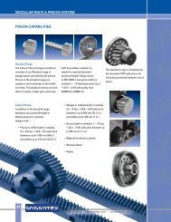
2 FLANGE UNITS, INCH SERIES<br />
DIMENSIONS – 2 FLANGE UNITS *<br />
Model Type A B C D E F G H I J K L<br />
R3000/R3000-2 2-Way 0.375 0.59 1.385 2.85 - 0.656 0.203 1.25 0.438 0.594 0.177 2.165<br />
R3100/R3100-2 3-Way 0.375 0.59 1.385 2.85 0.59 0.656 0.203 1.25 0.438 0.594 0.177 2.165<br />
R3200/R3200-2 2-Way 0.625 1.50 2.125 5.00 - 0.937 0.265 2.00 0.687 0.937 0.265 3.25<br />
R3300/R3300-2 3-Way 0.625 1.50 2.125 5.00 1.375 0.937 0.265 2.00 0.687 0.937 0.265 3.25<br />
*Model Numbers followed by “-2” indicates 2:1 reduction. 1:1 & 2:1 units have the same dimensions. Complete outline drawings are available upon request.<br />
Shaft diameter tolerances are +0.000/-0.001. All dimensions are in inches and are subject to change.<br />
Keyway Dimensions: SIZE 1 – R-3000 / R3000-2 / R3100 / R3100-2: None<br />
SIZE 2 – R-3200 / R3200-2 / R3300 / R3300-2: 3/16W x 3/32H x 1 1/2L<br />
800-713-6170 • www.andantex.com • info@andantex.com<br />
4
SELECTION & ORDERING INFORMATION, INCH SERIES<br />
Selection Procedure<br />
1. Determine the output speed and torque required for your application. The maximum recommended output<br />
speed is 3000 rpm for 1:1 units, and 1500 rpm for 2:1 units. 2:1 units are NOT recommended for use as<br />
speed increasers.<br />
2. Select an application service factor from the chart to the right. Multiply your torque by the selected service<br />
factor. If you are unsure of the factor to be used, please consult us.<br />
3. Using the chart below, find your output speed on the left. If your speed is not shown, use the next highest<br />
speed. Depending on the ratio you need (1:1 or 2:1) , follow the chart across until you find a torque value<br />
that is larger than your corrected torque value.<br />
4. The Unit Size you need will be at the top of that column. There are 5 sizes available. At the bottom of the<br />
column is a list of the various models available under the selected size. Select the model number; based<br />
on the gear ratio and the number of shafts you need (2 or 3). When ordering, use the model number you<br />
selected, along with the ratio desired.<br />
5. Check the applied radial and thrust loads on the unit compared with loads in the chart at the bottom of the<br />
page. If the applied loads are larger than the chart values, a larger unit must be selected.<br />
6. Refer back to pages 4 and 5 for dimensional information on the model you selected.<br />
OPERATING UNIFORM MODERATE<br />
CONDITIONS LOAD SHOCK<br />
SERVICE<br />
(hours/day)<br />
SERVICE FACTORS<br />
3 0.7 0.9<br />
8 0.9 1<br />
12 1 1.3<br />
24 1.3 1.8<br />
T (in.lb) = 63,000 x HP / RPM<br />
HP = T x RPM / 63,000<br />
OUTPUT SPEED (RPM)<br />
SIZE 1 SIZE 2 SIZE 3 SIZE 4 SIZE 5<br />
Ratio 1:1 2:1 1:1 2:1 1:1 2:1 1:1 2:1 1:1<br />
RATINGS* in.lb HP in.lb HP in.lb HP in.lb HP in.lb HP in.lb HP in.lb HP in.lb HP in.lb HP<br />
50 17 0.01 10 0.01 51 0.04 32 0.03 229 0.18 125 0.10 400 0.32 193 0.15 800 0.63<br />
100 16 0.03 10 0.02 49 0.08 30 0.05 215 0.34 117 0.19 370 0.59 182 0.29 740 1.17<br />
200 15 0.05 9 0.03 48 0.15 28 0.09 207 0.66 110 0.35 345 1.10 172 0.55 700 2.22<br />
300 15 0.07 9 0.04 47 0.23 27 0.13 205 0.98 105 0.50 325 1.55 162 0.77 660 3.14<br />
400 14 0.09 8 0.05 47 0.30 26 0.17 203 1.29 100 0.63 310 1.97 154 0.98 625 3.97<br />
500 14 0.11 8 0.06 46 0.37 25 0.20 200 1.59 96 0.76 300 2.38 148 1.17 600 4.76<br />
750 13 0.15 8 0.09 46 0.54 24 0.29 196 2.34 91 1.08 278 3.31 137 1.63 565 6.73<br />
1000 13 0.20 8 0.12 45 0.71 23 0.37 193 3.06 87 1.38 265 4.21 130 2.06 540 8.57<br />
1250 13 0.25 7 0.14 44 0.88 23 0.45 190 3.77 84 1.67 260 5.16 128 2.53 520 10.32<br />
1500 13 0.30 7 0.17 44 1.05 23 0.54 187 4.45 81 1.93 257 6.11 125 2.98 500 11.90<br />
1750 12 0.34 43 1.21 185 5.14 254 7.04 485 13.47<br />
2000 12 0.39 43 1.37 183 5.80 250 7.95 470 14.92<br />
2500 12 0.48 42 1.68 179 7.11 245 9.73 448 17.76<br />
3000 12 0.57 42 1.99 176 8.39 241 11.5 425 20.24<br />
2-WAY R3000 R3000-2 R3200 R3200-2 R3330 R3330-2 R3400 R3400-2 R3570<br />
3-WAY R3100 R3100-2 R3300 R3300-2 R3350 R3350-2 R3500 R3500-2 R3590<br />
2-WAY R3003 R3003-2 R3203 R3203-2<br />
3-WAY R3103 R3103-2 R3303 R3303-2<br />
MODEL<br />
DATA (lbs)<br />
R3000 R3100 R3200 R3300 R3330 R3350 R3400 R3500 R3570 R3590<br />
1:1 2:1 1:1 2:1 1:1 2:1 1:1 2:1 1:1 2:1 1:1 2:1 1:1 2:1 1:1 2:1 1:1 1:1<br />
RADIAL LOAD 25 25 25 25 50 50 50 50 100 100 100 100 100 100 100 100 100 100<br />
THURST LOAD 50 50 50 50 100 100 100 100 200 200 200 200 200 200 200 200 200 200<br />
WEIGHT 0.5 0.5 0.5 0.5 2.2 2.2 2.4 2.4 8.7 8.7 9.0 9.0 14.5 14.5 15 15 17.5 18<br />
* Unit ratings are: Output Torque in in.lb and Output Power in HP.<br />
Selection Example<br />
An application to connect a drive-shaft to a fan-shaft at a right-angle. Gearbox ratio to be 1:1. Input and output connections are<br />
with timing belt pulleys at 1000 rpm. Transmitted power is 1.34 HP. Operating conditions are moderate shock, 12 hours/day.<br />
1. Output speed is 1000 rpm. Operating torque = 63,000 x 1.34 HP / 1000 rpm = 84.4 in.lb.<br />
2. Service factor from chart (12 hours/day, moderate shock) – SF = 1.3. Corrected torque = 84.4 x 1.3 = 109.7 in.lb.<br />
3. From ratings chart (output speed = 1000 rpm), unit torque = 193 in.lb (>109.7 in.lb) – Size 3 1:1.<br />
4. The model selected is: R3330 for two-way or R3350 for three-way.<br />
5. The applied radial loads are calculated 800-713-6170 to be 74 • lb. www.andantex.com on each shaft (
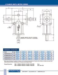
2 FLANGE UNITS, METRIC SERIES<br />
DIMENSIONS – 2 FLANGE UNITS *<br />
Model Type A B C D E F G H I J K L<br />
R3000M/R3000-2M 2-Way 8 15 34 76 - 16 5.2 33 11 15 4.2 60<br />
R3100M/R3100-2M 3-Way 8 15 34 76 15 16 5.2 33 11 15 4.2 60<br />
R3200M/R3200-2M 2-Way 15 35 52 125 - 24 8.3 52 18 26 6.2 90<br />
R3300M/R3300-2M 3-Way 15 35 52 125 35 24 8.3 52 18 26 6.2 90<br />
Model numbers followed by “-2” indicates 2:1 reduction. 1:1 & 2:1 units have the same dimensions. Complete outline drawings are available upon request. Shaft<br />
diameter tolerances are ISO f7. All dimensions are in millimeters and are subject to change.<br />
Keyway Dimensions: SIZE 1- R3000M / R3000-2M / R3100M / R3100-2M: None<br />
SIZE 2 -R3200M / R3200-2M / R3300M / R3300-2M: 5W x 2.5H x 25L<br />
7<br />
800-713-6170 • www.andantex.com • info@andantex.com
3 FLANGE UNITS, METRIC SERIES<br />
DIMENSIONS – 3 FLANGE UNITS *<br />
Model Type A B C D E F G H I J K L M<br />
R3003M/R3003-2M 2-Way 8 15 35 85 - 16.5 5.2 33 11 15 4.2 55 16.5<br />
R3103M/R3103-2M 3-Way 8 15 35 85 15 16.5 5.2 33 11 15 4.2 55 16.5<br />
R3203M/R3203-2M 2-Way 15 35 54 143 - 24 8.3 52 18 24 6.2 82.5 24<br />
R3303M/R3303-2M 3-Way 15 35 54 143 35 24 8.3 52 18 24 6.2 82.5 24<br />
R3330M/R3330-2M 2-Way 20 50 75 200 - 38 8.3 76 27 38 8.3 140 38<br />
R3350M/R3350-2M 3-Way 20 50 75 200 50 38 8.3 76 27 38 8.3 140 38<br />
R3400M/R3400-2M 2-Way 25 70 80 230 - 45 10.3 100 38 38 10.3 150 70<br />
R3500M/R3500-2M 3-Way 25 70 80 230 70 45 10.3 100 38 38 10.3 150 70<br />
R3600M/R3600-2M 2-Way 35 70 80 230 - 45 10.3 100 38 38 10.3 150 70<br />
R3700M-R3700-2M 3-Way 35 70 80 230 70 45 10.3 100 38 38 10.3 150 70<br />
Model numbers followed by “-2” indicates 2:1 reduction. 1:1 & 2:1 units have the same dimensions. Complete outline drawings are available upon request. Shaft<br />
diameter tolerances are ISO f7. All dimensions are in millimeters and are subject to change.<br />
Keyway Dimensions: SIZE 1 – R3003M / R3003-2M / R3103M / R3103-2M: None<br />
SIZE 2 – R3203M / R3203-2M / R3303M / R3303-2M: 5W x 2.5H x 25L<br />
SIZE 3 – R3330M / R3330-2M / R3350M / R3350-2M: 6W x 3H x 40L<br />
SIZE 4 – R3400M / R3400-2M / R3500M / R3500-2M: 8W x 3.5H x 60L<br />
SIZE 5 – R3600M / R3600-2M / R3700M / R3700-2M: 10W x 4H x 55L<br />
800-713-6170 • www.andantex.com • info@andantex.com<br />
8
SELECTION & ORDERING INFORMATION, METRIC SERIES<br />
Selection Procedure<br />
1. Determine the output speed and torque required for your application. The maximum recommended output<br />
speed is 3000 rpm for 1:1 units, and 1500 rpm for 2:1 units. 2:1 units are NOT recommended for use as<br />
speed increasers.<br />
2. Select an application service factor from the chart to the right. Multiply your torque by the selected<br />
service factor. If you are unsure of the factor to be used, please consult us.<br />
3. Using the chart below, find your output speed on the left. If your speed is not shown, use the next highest<br />
speed. Depending on the ratio you need (1:1 or 2:1), follow the chart across until you find a torque value<br />
that is larger than your corrected torque value.<br />
4. The Unit Size you need will be at the top of that column. There are 5 sizes available. At the bottom of the<br />
column is a list of the various models available under the selected size. Select the model number, based<br />
on the gear ratio and the number of shafts you need (2 or 3). When ordering, use the model number you<br />
selected, along with the ratio desired.<br />
5. Check the applied radial & thrust loads on the unit compared with the loads in the chart at the bottom.<br />
If the applied loads are larger than the chart values, a larger unit must be selected.<br />
6. Refer back to pages 4 & 5 for dimensional information on the model you selected.<br />
SERVICE FACTORS<br />
OPERATING UNIFORM MODERATE<br />
CONDITIONS LOAD SHOCK<br />
SERVICE<br />
(hours/day)<br />
3 1 1.3<br />
8 1.3 1.4<br />
12 1.4 1.8<br />
24 1.8 2.5<br />
T (Nm) = 9,550 x kW / RPM<br />
kW = T x RPM / 9,550<br />
OUTPUT SPEED (RPM)<br />
SIZE 1 SIZE 2 SIZE 3 SIZE 4 SIZE 5<br />
RATIO 1:1 2:1 1:1 2:1 1:1 2:1 1:1 2:1 1:1 2:1<br />
SPEED T kW T kW T kW T kW T kW T kW T kW T kW T kW T kW<br />
50 4.70 0.02 1.25 0.01 16.60 0.09 5.02 0.03 50.5 0.26 27 0.14 89 0.47 39.1 0.20 132 0.69 72.2 0.38<br />
100 4.20 0.04 1.09 0.01 14.50 0.15 4.65 0.05 44 0.46 26 0.27 79 0.83 37.4 0.39 118 1.24 67.7 0.71<br />
200 3.70 0.08 0.96 0.02 12.60 0.26 4.42 0.09 38 0.80 24.5 0.51 69 1.45 36.1 0.76 102 2.14 63.3 1.33<br />
300 3.40 0.11 0.91 0.03 11.60 0.36 4.20 0.13 34.7 1.09 23 0.72 62.9 1.98 34.9 1.10 93.2 2.93 61 1.92<br />
400 3.20 0.13 0.86 0.04 10.90 0.46 3.97 0.17 32.5 1.36 22 0.92 58.7 2.46 33.2 1.39 86.9 3.64 56.6 2.37<br />
500 3.07 0.16 0.84 0.04 10.45 0.55 3.86 0.20 31.1 1.63 21.5 1.13 55.9 2.93 32.3 1.69 82.7 4.33 55.1 2.88<br />
750 2.79 0.22 0.77 0.06 9.70 0.76 3.64 0.29 28.7 2.25 20.3 1.59 50.2 3.94 30.2 2.37 74.1 5.82 50.4 3.96<br />
1000 2.60 0.27 0.69 0.07 9.20 0.96 3.37 0.35 27.1 2.84 19 1.99 46.3 4.85 28.1 2.94 68.3 7.15 47.6 4.98<br />
1250 2.48 0.32 0.65 0.09 8.83 1.16 3.20 0.42 26 3.40 18 2.36 43.5 5.69 26 3.40 64.1 8.39 44.1 5.77<br />
1500 2.36 0.37 0.62 0.10 8.45 1.33 3.11 0.49 24.8 3.90 17.9 2.81 41.3 6.49 24.9 3.91 60.7 9.53 42.2 6.63<br />
1750 2.25 0.41 8.00 1.47 23.7 4.34 39.3 7.20 57.4 10.5<br />
2000 2.18 0.46 7.90 1.65 22.8 4.77 37.9 7.94 55.5 11.6<br />
2500 2.06 0.54 7.80 2.04 21.3 5.58 35.3 9.24 51.6 13.5<br />
3000 1.95 0.61 7.70 2.42 20.2 6.35 33.3 10.5 48.6 15.3<br />
2-WAY R3000M R3000-2M R3200M R3200-2M R3330M R3330-2M R3400M R3400-2M R3600M R3600-2M<br />
3-WAY R3100M R3100-2M R3300M R3300-2M R3350M R3350-2M R3500M R3500-2M R3700M R3700-2M<br />
2-WAY R3003M R3003-2M R3203M R3203-2M<br />
3-WAY R3103M R3103-2M R3303M R3303-2M<br />
MODEL<br />
DATA (kg)<br />
R3000M R3100M R3200M R3300M R3330M R3350M R3400M R3500M R3600M R3700M<br />
1:1 2:1 1:1 2:1 1:1 2:1 1:1 2:1 1:1 2:1 1:1 2:1 1:1 2:1 1:1 2:1 1:1 2:1 1:1 2:1<br />
RADIAL LOAD 11.4 11.4 11.4 11.4 22.7 22.7 22.7 22.7 45.4 45.4 45.4 45.4 45.4 45.4 45.4 45.4 45.4 45.4 45.4 45.4<br />
THRUST LOAD 22.7 22.7 22.7 22.7 45.4 45.4 45.4 45.4 90.7 90.7 90.7 90.7 90.7 90.7 90.7 90.7 90.7 90.7 90.7 90.7<br />
WEIGHT 0.23 0.23 0.23 0.23 1.00 1.00 1.09 1.09 3.95 3.95 4.08 4.08 6.58 6.58 6.80 6.80 7.94 7.94 8.16 8.16<br />
* Unit ratings are: Output Torque in Nm and Output Power in kW.<br />
9<br />
Selection Example<br />
An application to connect a drive-shaft to a fan-shaft at a right-angle with a 1:1 ratio. Input & output connections with timing<br />
belt pulleys at 1,000 rpm. Input power is 1 kW. Operating conditions are moderate shock, 12 hr/day.<br />
1. Output speed is 1000 rpm. Operating torque = 9,550 x 1 kW / 1000 rpm = 9.55 Nm.<br />
2. Service factor from chart (12 hours/day, moderate shock) - SF=1.3. Corrected torque = 9.55 x 1.3 = 12.42 Nm.<br />
3. From ratings chart (output speed = 1000 rpm), unit torque = 27.1 Nm (> 12.42 Nm) - Size 3 1:1.<br />
4. The model selected is: R3330M for two-way or R3350M for three-way.<br />
5. The applied radial loads are calculated<br />
800-713-6170<br />
to be 33.6 kg<br />
•<br />
on<br />
www.andantex.com<br />
each shaft (< 45.4 kg),<br />
•<br />
which<br />
info@andantex.com<br />
is allowable.<br />
6. On pages 7 & 8, the dimensions are checked to confirm available space for model selected.
SPECIAL UNITS<br />
The photo above shows examples of special units that <strong>Andantex</strong> <strong>USA</strong> has designed/modified to meet<br />
our customers’ requirements. We will design/modify any unit to meet your design specifications.<br />
Special models can be provided with:<br />
- Various shaft lengths and configurations.<br />
- Same relative rotation of input-to-output shafts (BO)<br />
- 3-way units with counter-rotating output shafts.<br />
- Shafts with flats, splines, holes, etc.<br />
- Modifications to the mounting flanges and housing.<br />
- Special materials, bearings, seals, greases, coatings, etc.<br />
Service & Replacement Parts<br />
All units can be serviced at our factory in Wanamassa, NJ.<br />
Field repairs are not covered under our warranty. Unit parts<br />
lists are available upon request. Spare parts may be<br />
purchased from our factory, and are non-returnable.<br />
Warranty<br />
ANDANTEX <strong>USA</strong> <strong>Inc</strong>., the manufacturer, warrants that for a<br />
period of 12 months from the date of installation or 18<br />
months from the date of shipment, it will repair, or at its<br />
option, replace any new unit which proves defective in<br />
material or workmanship, or which does not conform to<br />
applicable drawings and specifications approved by the<br />
manufacturer. All repairs and replacements shall be F.O.B.<br />
factory. All claims must be made in writing to the<br />
manufacturer.<br />
In no event, and under no circumstances shall the<br />
manufacturer be liable for (a) damages in shipment; (b)<br />
failures or damages due to misuse, abuse, improper<br />
installation or abnormal conditions of temperature, dirt,<br />
water or corrosives; (c) failures due to operation, intentional<br />
or otherwise, above rated capacities, and (d) non-authorized<br />
expenses for removal, inspection, transportation, repair or<br />
rework. Nor shall the manufacturer ever be liable for<br />
consequential and incidental damages, or in any amount<br />
greater than the purchase price of the unit.<br />
This warranty is in LIEU OF ALL OTHER WARRANTIES, EXPRESS OR<br />
IMPLIED, INCLUDING (BUT NOT LIMITED TO) ANY IMPLIED<br />
WARRANTIES OF MERCHANT ABILITY OR FITNESS FOR A<br />
PARTICULAR PURPOSE. THE TERMS OF THIS WARRANTY<br />
CONSTITUTE ALL BUYER’S OR USER’S SOLE AND EXCLUSIVE<br />
REMEDY, AND ARE IN LIEU OF ANY RIGHT TO RECOVER<br />
FOR NEGLIGENCE, BREACH OF WARRANTY, STRICT<br />
TORT LIABILITY OR UPON ANY OTHER THEORY.<br />
800-713-6170 • www.andantex.com • info@andantex.com<br />
10
1705 Valley Road • Wanamassa, NJ 07712<br />
Phone: 800.713.6170 • 732.493.2812 • Fax: 732.493.2949 • E-mail: info@andantex.com • www.andantex.com