MODULAR RACK & PINION SYSTEM - Andantex USA Inc.
MODULAR RACK & PINION SYSTEM - Andantex USA Inc.
MODULAR RACK & PINION SYSTEM - Andantex USA Inc.

You also want an ePaper? Increase the reach of your titles
YUMPU automatically turns print PDFs into web optimized ePapers that Google loves.
<strong>MODULAR</strong> <strong>RACK</strong><br />
& <strong>PINION</strong> <strong>SYSTEM</strong><br />
800-713-6170 • www.andantex.com • info@andantex.com
<strong>MODULAR</strong> <strong>RACK</strong> & <strong>PINION</strong> <strong>SYSTEM</strong><br />
INTRODUCTION<br />
<strong>Andantex</strong>, <strong>USA</strong> has introduced two new products under the brand<br />
name and joined forces with world class rack manufacturers to provide<br />
North American customers complete solutions to Rack and pinion Axis drives.<br />
The complete solution is built<br />
from standard building blocks<br />
and it consists of:<br />
- Racks & Pinions<br />
- Precision speed reducer<br />
- Automatic Rack Lubrication system<br />
- Servo-Motor mounting flange<br />
- Engineering selection and<br />
guidance to optimize the solution<br />
- Installation instructions<br />
and assistance<br />
The axis building blocks consist of:<br />
A. Modular rack & pinion system<br />
providing standard rack<br />
sections for building any length<br />
or precision linear axis.<br />
B. AE Servo-Worm reducers for<br />
positioning applications<br />
C. SRP High-Tech servo-planetary<br />
reducers for precise positioning,<br />
contouring and heavily loaded<br />
applications.<br />
D. DRP+ & KRP+ DualDrive<br />
& TwinDrive reducers for<br />
Zero-Backlash applications<br />
The range of products insures<br />
that <strong>Andantex</strong> can provide the<br />
rack & pinion drive system with<br />
the correct balance of precision,<br />
power and price for typical<br />
linear motion applications:<br />
- Axis requiring precise positioning<br />
and repeatability<br />
- Traveling gantry horizontal and<br />
vertical axis drives<br />
- Pick and place robots<br />
- Replacements for long ballscrew<br />
axis drives<br />
- Zero-Backlash positioning and<br />
contouring drives<br />
These applications are found in<br />
the following industries and<br />
machines:<br />
- Machine Tool<br />
• Gantry Milling Machine<br />
• Moving Column Jig<br />
Boring Machines<br />
• Large Turning Machines<br />
- Carbon Fiber Placement machines<br />
- Material Handling Machinery<br />
- Ultrasonic inspection Machinery<br />
- Cutting Machines<br />
• Laser<br />
• Waterjet<br />
• Plasma cutting<br />
• Stone cutting<br />
A.<br />
B.<br />
C.<br />
D.<br />
2<br />
800-713-6170 • www.andantex.com • info@andantex.com
<strong>MODULAR</strong> <strong>RACK</strong> & <strong>PINION</strong> <strong>SYSTEM</strong><br />
Modular Rack & Pinion System<br />
- Description<br />
This system consists of a standard<br />
range of straight, circumferential pitch,<br />
and helical racks and pinions. The<br />
modular design permits rack lengths<br />
from 0.5 meters to 2 meters to be<br />
linked end to end achieving any desired<br />
travel length from standard components.<br />
Racks & pinions are available with<br />
different materials, heat treatments and<br />
quality levels to insure the correct<br />
balance of power, precision and price<br />
to meet application requirements. The<br />
table below summarizes this point:<br />
CONTENTS<br />
PG #<br />
Introduction – Rack & Pinion Axis Drives 2<br />
Modular Rack & Pinion System Description 3<br />
Rack Capabilities 4<br />
Standard Range of Racks 5<br />
Standard Rack Dimensions 6<br />
Pinion Capabilities 16<br />
Standard Range of Pinions 17<br />
Pinion Dimensions 18<br />
Rack & Pinion Torque Ratings 26<br />
Rack & Pinion Selection & Calculations 29<br />
Rack & Pinion Application Data Sheet 32<br />
Lubrication Recommendations & Components 33<br />
Rack & Pinion Installation Guidelines 37<br />
AVAILABLE QUALITY LEVELS<br />
Description Material Hardness Quality Relative Torque Relative Relative<br />
Capacity * Pitch Error Cost<br />
Hardened 16MnCr5 (AISI 51L17) 60 Rc AGMA 12 ✦✦✦ ✦ $$$<br />
& Ground C45 (AISI 1045)<br />
Quenched 42CrMo4V (AISI 4140) 27 Rc AGMA 10 ✦ ✦✦ $$<br />
& Tempered<br />
Induction Ck45k (AISI 10L45) 55 Rc AGMA 8 ✦✦ ✦✦✦ $<br />
Hardened<br />
Cost effective automatic lubrication systems are available<br />
to insure long life and trouble free operation.<br />
The modular rack & pinion system is the primary building block<br />
of a linear axis drive.<br />
Rack and pinions are manufactured by: Güdel or WMH Herion.<br />
The standard range is available in<br />
modules, M, 1.0 to 10.0 (Diametral<br />
pitch, P, 25.4 to 2.54) with lengths up<br />
to 2 meters allowing loads from 1 Lb.<br />
to 100,000 Lbs. to be moved at speeds<br />
from 0 to 1000 ft/s (5 M/s). Rack<br />
lengths up to 4 meters (2 meters with<br />
ground teeth) and modules up to 20<br />
are available on request.<br />
800-713-6170 • www.andantex.com • info@andantex.com<br />
3
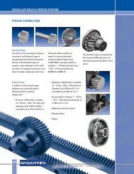
<strong>MODULAR</strong> <strong>RACK</strong> & <strong>PINION</strong> <strong>SYSTEM</strong><br />
<strong>RACK</strong> CAPABILITIES<br />
Standard Range:<br />
The index on the next page provides<br />
an overview of our Standard range of<br />
straight (spur) and helical tooth racks.<br />
Racks in the standard range are<br />
usually in stock allowing for short<br />
delivery times. The standard range<br />
consists of rectangular profile steel<br />
racks in modules 1 – 10 with lengths<br />
up to 2 meters and quality from<br />
AGMA 8 to AGMA 12.<br />
Custom Racks:<br />
In addition to the standard range,<br />
<strong>Andantex</strong> can provide Straight or<br />
Helical racks to customer designs with:<br />
• Precision milled teeth in modules<br />
0.5 - 20 (diametral pitch 50.8 to<br />
1.27) in lengths up to 4 meters.<br />
• Ground Teeth in modules 1-10<br />
(diametral pitch 25.4 to 2.54)<br />
in lengths up to 2 meters.<br />
• Quality Levels of up to<br />
AGMA 13 (DIN 5)<br />
• Material hardened or plated<br />
• Round Sections<br />
• Stainless Steel<br />
• Plastic<br />
4<br />
800-713-6170 • www.andantex.com • info@andantex.com
<strong>MODULAR</strong> <strong>RACK</strong> & <strong>PINION</strong> <strong>SYSTEM</strong><br />
RANGE OF <strong>RACK</strong>S<br />
Series Style Module<br />
Heat<br />
Treatment<br />
Quality<br />
Level<br />
Page<br />
A10 Straight (spur) 1.5, 2, 2.5, 3, Hardened & 6 h 25 6<br />
4, 5, 6, 8, 10 Ground (~AGMA 12)<br />
A20 Straight (spur) 2, 3, 4 Quenched & 8 e 27 7<br />
Tempered (~AGMA 10)<br />
A30 Straight (spur) 1, 1.5, 2, 2.5, Soft 9 e 27 8<br />
3, 4, 5, 6, 8 (~AGMA 9)<br />
A40 Straight (spur) 2, 3, 4 Induction 10 e 27 9<br />
Hardened (~AGMA 8)<br />
A50 Straight (spur) 2, 5, 7.5, 10 Hardened & 6 h 23 10<br />
circular pitch, p Ground (~AGMA 12)<br />
A60 Straight (spur) 10, 12.5, 16, 20, 25 Induction 9 h 25 11<br />
circular pitch, p Hardened (~AGMA 9)<br />
A70 Straight (spur) 2, 5, 7.5, 10, 12.5 Soft 7 h 25 12<br />
circular pitch, p (~AGMA 11)<br />
A11 Helical 1.5, 2, 2.5, 3, 4, Hardened & 6 h 25 13<br />
5, 6, 8, 10 Ground (~AGMA 12)<br />
A21 Helical 2, 3, 4 Quenched & 8 e 27 14<br />
Tempered (~AGMA 10)<br />
A31 Helical 2, 3, 4 Soft 9 e 27<br />
(~AGMA 9)<br />
On request<br />
A41 Helical 2, 3, 4 Induction 10 e 27 15<br />
Hardened (~AGMA 8)<br />
Tooth Style and quality<br />
Module or Circular pitch, mm<br />
Part Numbering System<br />
A11 02 0 200<br />
Options<br />
Rack Length in cm.<br />
With or Without Holes<br />
0 = holes, 1 = no holes<br />
800-713-6170 • www.andantex.com • info@andantex.com<br />
5
<strong>MODULAR</strong> <strong>RACK</strong> & <strong>PINION</strong> <strong>SYSTEM</strong><br />
<strong>RACK</strong>S<br />
WITH STRAIGHT (SPUR) TEETH<br />
SERIES A10<br />
Case Hardened & Ground Teeth<br />
Quality DIN 6 h 25 (~AGMA12)<br />
20° Pressure Angle<br />
Module L1 I1 teeth b h ho f a l<br />
No.<br />
holes h1 d1 d2 t a1 d3 Fp<br />
mass<br />
kg. Part No.<br />
1.5 499.51 441.5 106 19 19 17.5 2 62.44 124.88 4 8 7 11 7 29 5.7 0.029 1.3 A10-1.50-050<br />
1.5 499.51 441.5 106 19 19 17.5 2 without holes 0.029 1.3 A10-1.51-050<br />
1.5 999.03 941 212 19 19 17.5 2 62.44 124.88 8 8 7 11 7 29 5.7 0.043 2.6 A10-1.50-100<br />
1.5 999.03 941 212 19 19 17.5 2 without holes 0.043 2.6 A10-1.51-100<br />
1.5 Companion Rack for assembly A10-1.51-999<br />
2.0 502.7 440.1 80 24 24 22 2 62.83 125.66 4 8 7 11 7 31.3 5.7 0.025 2.1 A10-020-050<br />
2.0 502.7 440.1 80 24 24 22 2 without holes 0.025 2.1 A10-021-050<br />
2.0 1005.3 942.7 160 24 24 22 2 62.83 125.66 8 8 7 11 7 31.3 5.7 0.036 4.2 A10-020-100<br />
2.0 1005.3 942.7 160 24 24 22 2 without holes 0.036 4.2 A10-021-100<br />
2.0 Companion Rack for assembly A10-021-999<br />
2.5 502.65 440.1 64 24 24 21.5 2 62.83 125.66 4 9 7 11 7 31.3 5.7 0.027 2.0 A10-2.50-050<br />
2.5 502.65 440.1 64 24 24 21.5 2 without holes 0.027 2.0 A10-2.51-050<br />
2.5 1005.31 942.7 128 24 24 21.5 2 62.83 125.66 8 9 7 11 7 31.3 5.7 0.036 4.1 A10-2.50-100<br />
2.5 1005.31 942.7 128 24 24 21.5 2 without holes 0.036 4.1 A10-2.51-100<br />
2.5 Companion Rack for assembly A10-2.51-999<br />
3.0 508.9 440.1 54 29 29 26 2 63.62 127.23 4 9 10 15 9 34.4 7.7 0.029 3 A10-030-050<br />
3.0 508.9 440.1 54 29 29 26 2 without holes 0.029 3 A10-031-050<br />
3.0 1017.9 949.1 108 29 29 26 2 63.62 127.23 8 9 10 15 9 34.4 7.7 0.037 6 A10-030-100<br />
3.0 1017.9 949.1 108 29 29 26 2 without holes 0.037 6 A10-031-100<br />
3.0 Companion Rack for assembly A10-031-999<br />
4.0 502.7 427.7 40 39 39 35 3 62.83 125.66 4 12 10 15 9 37.5 7.7 0.030 5.4 A10-040-050<br />
4.0 502.7 427.7 40 39 39 35 3 without holes 0.030 5.4 A10-041-050<br />
4.0 1005.3 930.3 80 39 39 35 3 62.83 125.66 8 12 10 15 9 37.5 7.7 0.037 10.8 A10-040-100<br />
4.0 1005.3 930.3 80 39 39 35 3 without holes 0.037 10.8 A10-041-100<br />
4.0 Companion Rack for assembly A10-041-999<br />
5.0 502.6 442.3 32 49 39 34 3 62.83 125.66 4 12 14 20 13 30.2 11.7 0.028 6.6 A10-050-050<br />
5.0 502.6 442.3 32 49 39 34 3 without holes 0.028 6.6 A10-051-050<br />
5.0 1005.3 944.9 64 49 39 34 3 62.83 125.66 8 12 14 20 13 30.2 11.7 0.034 13.1 A10-050-100<br />
5.0 1005.3 944.9 64 49 39 34 3 without holes 0.034 13.1 A10-051-100<br />
5.0 Companion Rack for assembly A10-051-999<br />
6.0 508.9 446.1 27 59 49 43 3 63.62 127.23 4 16 18 26 17 31.4 15.7 0.031 10.1 A10-060-050<br />
6.0 508.9 446.1 27 59 49 43 3 without holes 0.031 10.1 A10-061-050<br />
6.0 1017.8 955 54 59 49 43 3 63.62 127.23 8 16 18 26 17 31.4 15.7 0.036 20.3 A10-060-100<br />
6.0 1017.8 955 54 59 49 43 3 without holes 0.036 20.3 A10-061-100<br />
6.0 Companion Rack for assembly A10-061-999<br />
8.0 502.65 449.3 20 79 79 71.0 3 62.83 125.66 4 25 22 33 21 26.7 19.7 0.029 22.1 A10-080-050<br />
8.0 502.65 449.3 20 79 79 71.0 3 without holes 0.029 22.1 A10-081-050<br />
8.0 1005.3 952 40 79 79 71.0 3 62.83 125.66 8 25 22 33 21 26.7 19.7 0.033 44.3 A10-080-100<br />
8.0 1005.3 952 40 79 79 71.0 3 without holes 0.033 44.3 A10-081-100<br />
8.0 Companion Rack for assembly A10-081-999<br />
10.0 1005.3 755 32 99 99 89 3 62.83 125.66 8 32 33 48 32 125.2 19.7 0.04 69 A10-100-100<br />
10.0 1005.3 755 32 99 99 89 3 without holes 0.04 69 A10-101-100<br />
10.0 Companion Rack for assembly A10-101-999<br />
6<br />
Material AISI 1045 (C45) with tensile strength = 650 N/mm 2 (95,000 PSI). Teeth induction<br />
hardened to 50-55 Rc: ground on all sides after hardening. (Alternate material modules 2-4<br />
AISI 5115 (16MnCr5) hardened to 60 Rc). Only teeth are hardened allowing subsequent<br />
drilling and pinning of rack. Rack ends are machined for continuous mounting.<br />
Fp is the max cumulative pitch error for the corresponding rack length.<br />
Dimensions are in mm and are subject to change - consult factory.<br />
800-713-6170 • www.andantex.com • info@andantex.com
<strong>MODULAR</strong> <strong>RACK</strong> & <strong>PINION</strong> <strong>SYSTEM</strong><br />
SERIES A20<br />
Quenched & Tempered Material<br />
Quality DIN 8 e 27 (~AGMA10)<br />
20° Pressure Angle<br />
<strong>RACK</strong>S<br />
WITH STRAIGHT (SPUR) TEETH<br />
Module L1 I1 teeth b h ho f a l<br />
No.<br />
holes h1 d1 d2 t a1 d3 Fp<br />
mass<br />
kg. Part No.<br />
2.0 502.7 440.1 80 25 24 22 2 62.83 125.66 4 8 7 11 7 31.3 5.7 2.1 A20-020-050<br />
2.0 502.7 440.1 80 25 24 22 2 without holes 2.1 A20-021-050<br />
2.0 1005.3 942.7 160 25 24 22 2 62.83 125.66 8 8 7 11 7 31.3 5.7 0.063 4.2 A20-020-100<br />
2.0 1005.3 942.7 160 25 24 22 2 without holes 0.063 4.2 A20-021-100<br />
2.0 Companion Rack for assembly A20-021-999<br />
3.0 508.9 440.1 54 30 29 26 2 63.62 127.23 4 9 10 15 9 34.4 7.7 3 A20-030-050<br />
3.0 508.9 440.1 54 30 29 26 2 without holes 3 A20-031-050<br />
3.0 1017.9 949.1 108 30 29 26 2 63.62 127.23 8 9 10 15 9 34.4 7.7 0.071 6 A20-030-100<br />
3.0 1017.9 949.1 108 30 29 26 2 without holes 0.071 6 A20-031-100<br />
3.0 Companion Rack for assembly A20-031-999<br />
4.0 502.7 427.7 40 40 39 35 3 62.83 125.66 4 12 10 15 9 37.5 7.7 5.3 A20-040-050<br />
4.0 502.7 427.7 40 40 39 35 3 without holes 5.3 A20-041-050<br />
4.0 1005.3 930.3 80 40 39 35 3 62.83 125.66 8 12 10 15 9 37.5 7.7 0.08 10.5 A20-040-100<br />
4.0 1005.3 930.3 80 40 39 35 3 without holes 0.08 10.5 A20-041-100<br />
4.0 Companion Rack for assembly A20-041-999<br />
Material AISI 4140 (42CrMo4V) with tensile strength = 900 N/mm 2 (130,500 PSI).<br />
Back and contact face ground. Rack ends are machined for continuous mounting.<br />
Fp is the max cumulative pitch error for the corresponding rack length.<br />
Dimensions are in mm and are subject to change - consult factory.<br />
800-713-6170 • www.andantex.com • info@andantex.com<br />
7
<strong>MODULAR</strong> <strong>RACK</strong> & <strong>PINION</strong> <strong>SYSTEM</strong><br />
<strong>RACK</strong>S<br />
WITH STRAIGHT (SPUR) TEETH<br />
SERIES A30<br />
Soft Rack<br />
Quality DIN 9 e 27 (~AGMA 9)<br />
20° Pressure Angle<br />
Module L1 teeth b h ho a l<br />
No.<br />
holes h1 d1 d2 t a1 d3 Fp<br />
mass<br />
kg. Part No.<br />
1.0 499.51 159 10 9.8 8.8 without holes 0.34 A30-011-050<br />
1.0 999.03 318 10 9.8 8.8 without holes 0.09 0.68 A30-011-100<br />
1.0 Companion Rack for assembly A30-011-999<br />
1.5 499.51 106 15 14.8 13.3 without holes 0.8 A30-1.51-050<br />
1.5 999.03 212 15 14.8 13.3 without holes 0.09 1.6 A30-1.51-100<br />
1.5 1998.05 424 15 14.8 13.3 without holes 3.1 A30-1.51-200<br />
1.5 Companion Rack for assembly A30-1.51-999<br />
2.0 502.65 80 20 19.75 17.75 without holes 1.4 A30-021-050<br />
2.0 999.03 159 20 19.75 17.75 without holes 0.09 2.8 A30-021-100<br />
2.0 1998.05 318 20 19.75 17.75 without holes 5.6 A30-021-200<br />
2.0 Companion Rack for assembly A20-021-999<br />
2.5 502.65 64 25 24.75 22.25 without holes 2.1 A30-2.51-050<br />
2.5 997.46 127 25 24.75 22.25 without holes 0.100 4.2 A30-2.51-100<br />
2.5 2002.76 255 25 24.75 22.25 without holes 8.4 A30-2.51-200<br />
2.5 Companion Rack for assembly A30-2.51-999<br />
3.0 499.51 53 30 29.75 26.75 without holes 3.1 A30-031-050<br />
3.0 999.03 106 30 29.75 26.75 without holes 0.100 6.2 A30-031-100<br />
3.0 1998.05 212 30 29.75 26.75 without holes 12.4 A30-031-200<br />
3.0 Companion Rack for assembly A20-031-999<br />
4.0 502.65 40 40 39.7 35.7 without holes 5.5 A30-041-050<br />
4.0 1005.31 80 40 39.7 35.7 without holes 0.110 11 A30-041-100<br />
4.0 1998.05 159 40 39.7 35.7 without holes 22 A30-041-200<br />
4.0 Companion Rack for assembly A20-041-999<br />
5.0 502.65 32 50 49.7 44.7 without holes 8.6 A30-051-050<br />
5.0 1005.31 64 50 49.7 44.7 without holes 0.110 17.2 A30-051-100<br />
5.0 2010.62 128 50 49.7 44.7 without holes 34.4 A30-051-200<br />
5.0 Companion Rack for assembly A30-051-999<br />
6.0 508.94 27 60 59.65 53.65 without holes 12.3 A30-061-050<br />
6.0 999.03 53 60 59.65 53.65 without holes 0.110 24.5 A30-061-100<br />
6.0 1998.05 106 60 59.65 53.65 without holes 49 A30-061-200<br />
6.0 Companion Rack for assembly A30-061-999<br />
8.0 502.65 20 80 79.6 71.6 without holes 21.4 A30-081-050<br />
8.0 1005.31 40 80 79.6 71.6 without holes 0.110 42.7 A30-081-100<br />
8.0 2010.62 80 80 79.6 71.6 without holes 85.4 A30-081-200<br />
8.0 Companion Rack for assembly A30-081-999<br />
Material AISI 1045 (C45) with tensile strength = 650 N/mm 2 (95,000 PSI).<br />
Rack ends are machined for continuous mounting.<br />
Fp is the max cumulative pitch error for the corresponding rack length.<br />
Dimensions are in mm and are subject to change - consult factory.<br />
8<br />
800-713-6170 • www.andantex.com • info@andantex.com
<strong>MODULAR</strong> <strong>RACK</strong> & <strong>PINION</strong> <strong>SYSTEM</strong><br />
SERIES A40<br />
Induction Hardened Teeth<br />
Quality DIN 10 e 27 (~AGMA 8)<br />
20° Pressure Angle<br />
<strong>RACK</strong>S<br />
WITH STRAIGHT (SPUR) TEETH<br />
Module L1 I1 teeth b h ho f a l<br />
No.<br />
holes h1 d1 d2 t a1 d3 Fp<br />
mass<br />
kg. Part No.<br />
2.0 502.7 440.1 80 24 24 22 2 62.83 125.66 4 8 7 11 7 31.3 5.7 2.1 A40-020-050<br />
2.0 502.7 440.1 80 24 24 22 2 without holes 2.1 A40-021-050<br />
2.0 1005.3 942.7 160 24 24 22 2 62.83 125.66 8 8 7 11 7 31.3 5.7 0.140 4.2 A40-020-100<br />
2.0 1005.3 942.7 160 24 24 22 2 without holes 0.140 4.2 A40-021-100<br />
2.0 Companion Rack for assembly A20-021-999<br />
3.0 508.9 440.1 54 29 29 26 2 63.62 127.23 4 9 10 15 9 34.4 7.7 3 A40-030-050<br />
3.0 508.9 440.1 54 29 29 26 2 without holes 3 A40-031-050<br />
3.0 1017.9 949.1 108 29 29 26 2 63.62 127.23 8 9 10 15 9 34.4 7.7 0.160 6 A40-030-100<br />
3.0 1017.9 949.1 108 29 29 26 2 without holes 0.160 6 A40-031-100<br />
3.0 Companion Rack for assembly A20-031-999<br />
4.0 502.7 427.7 40 39 39 35 3 62.83 125.66 4 12 10 15 9 37.5 7.7 5.3 A40-040-050<br />
4.0 502.7 427.7 40 39 39 35 3 without holes 5.3 A40-041-050<br />
4.0 1005.3 930.3 80 39 39 35 3 62.83 125.66 8 12 10 15 9 37.5 7.7 0.180 10.5 A40-040-100<br />
4.0 1005.3 930.3 80 39 39 35 3 without holes 0.180 10.5 A40-041-100<br />
4.0 Companion Rack for assembly A20-041-999<br />
Material AISI 1045 (C45) with tensile strength = 650 N/mm 2 (95,000 PSI). Teeth are induction<br />
hardened to 50-55Rc. Back and contact faces are machined after hardening. Only teeth are<br />
induction hardened allowing subsequent drilling and pinning of the rack. Rack ends are<br />
machined for continuous mounting.<br />
Fp is the max cumulative pitch error for the corresponding rack length.<br />
Dimensions are in mm and are subject to change - consult factory.<br />
800-713-6170 • www.andantex.com • info@andantex.com<br />
9
<strong>MODULAR</strong> <strong>RACK</strong> & <strong>PINION</strong> <strong>SYSTEM</strong><br />
<strong>RACK</strong>S<br />
WITH CIRCULAR PITCH STRAIGHT (SPUR) TEETH<br />
SERIES A50<br />
Case Hardened & Ground Teeth<br />
Quality DIN 6 h 23 (~AGMA12)<br />
20° Pressure Angle<br />
Circular<br />
Pitch, p Module L1 I teeth b h ho<br />
No.<br />
holes h1 d1 d2 t Fp<br />
mass<br />
kg. Part No.<br />
2.0 0.637 330 300 165 9.5 19.5 18.86 3 10.5 5.8 10 5.7 0.032 0.45 A50-020-033<br />
2.0 0.637 1030 1000 515 9.5 19.5 18.86 10 10.5 5.8 10 5.7 0.068 1.4 A50-020-103<br />
2.0 0.637 Companion Rack for assembly A50-021-999<br />
5.0 1.592 330 300 66 14.5 24.5 22.91 3 13 7 11 6.8 0.023 0.85 A50-050-033<br />
5.0 1.592 1030 1000 206 14.5 24.5 22.91 10 13 7 11 6.8 0.043 2.6 A50-050-103<br />
5.0 1.592 330 300 66 19.5 29.5 27.91 3 15.5 9 15 9 0.023 1.35 A50-050-033-19.5<br />
5.0 1.592 1030 1000 206 19.5 29.5 27.91 10 15.5 9 15 9 0.043 4.2 A50-050-103-19.5<br />
5.0 Companion Rack for assembly A50-051-999<br />
7.5 2.387 330 300 44 24.7 33 30.61 3 18.5 9 15 9 0.024 1.9 A50-7.50-033<br />
7.5 2.387 1230 1200 164 24.7 33 30.61 12 18.5 9 15 9 0.041 7 A50-7.50-123<br />
7.5 2.387 Companion Rack for assembly A50-7.51-999<br />
10.0 3.183 330 300 33 34.6 46.6 43.42 3 28.6 11 18 11 0.025 3.7 A50-100-033<br />
10.0 3.183 1230 1200 123 34.6 46.6 43.42 12 28.6 11 18 11 0.04 13.9 A50-100-123<br />
10.0 3.183 Companion Rack for assembly A50-101-999<br />
Material AISI 6150 (58CrMoV4). Teeth induction hardened to 50-60 Rc: ground on all sides<br />
after hardening. Only teeth are hardened allowing subsequent drilling and pinning of rack.<br />
Rack ends are machined for continuous mounting.<br />
Fp is the max cumulative pitch error for the corresponding rack length.<br />
Dimensions are in mm and are subject to change - consult factory.<br />
10<br />
800-713-6170 • www.andantex.com • info@andantex.com
<strong>MODULAR</strong> <strong>RACK</strong> & <strong>PINION</strong> <strong>SYSTEM</strong><br />
SERIES A60<br />
Induction Hardened Teeth<br />
Quality DIN 9 h 25 (~AGMA 9)<br />
20° Pressure Angle<br />
<strong>RACK</strong>S<br />
WITH CIRCULAR PITCH STRAIGHT (SPUR) TEETH<br />
Circular<br />
Pitch, p Module L1 I1 teeth b h ho<br />
No.<br />
holes h1 d1 d2 t Fp<br />
mass<br />
kg. Part No.<br />
10.0 3.183 800 700 80 29 29 25.82 9 11.5 9 15 9 0.092 4.8 A60-100-080<br />
10.0 3.183 1200 1100 120 29 29 25.82 13 11.5 9 15 9 0.108 7.2 A60-100-120<br />
10.0 3.183 2000 1900 200 29 29 25.82 21 11.5 9 15 9 0.142 12 A60-100-200<br />
10.0 3.183 Companion Rack for assembly A50-101-999<br />
12.5 3.979 800 700 64 39 39 35.02 9 14 11 18 11 0.094 9.8 A60-12.50-080<br />
12.5 3.979 1200 1100 96 39 39 35.02 13 14 11 18 11 0.108 13.5 A60-12.50-120<br />
12.5 3.979 2000 1900 160 39 39 35.02 21 14 11 18 11 0.137 22.5 A60-12.50-200<br />
12.5 3.979 Companion Rack for assembly A60-12.51-999<br />
16.0 5.093 800 700 50 49 49 43.91 9 24 13.5 20 13 0.088 14.2 A60-160-080<br />
16.0 5.093 1200 1100 75 49 49 43.91 13 24 13.5 20 13 0.099 21.2 A60-160-120<br />
16.0 5.093 2000 1900 125 49 49 43.91 21 24 13.5 20 13 0.121 35.3 A60-160-200<br />
16.0 5.093 Companion Rack for assembly A60-161-999<br />
20.0 6.366 800 700 40 59 59 52.63 9 29 13.5 20 13 0.094 20.2 A60-200-080<br />
20.0 6.366 1200 1100 60 59 59 52.63 13 29 13.5 20 13 0.104 30.3 A60-200-120<br />
20.0 6.366 2000 1900 100 59 59 52.63 21 29 13.5 20 13 0.125 50.5 A60-200-200<br />
20.0 6.366 Companion Rack for assembly A60-201-999<br />
25.0 7.958 800 700 32 79 79 71.04 9 39 17.5 26 17.5 0.09 35.7 A60-250-080<br />
25.0 7.958 1200 1100 48 79 79 71.04 13 39 17.5 26 17.5 0.098 53.6 A60-250-120<br />
25.0 7.958 2000 1900 80 79 79 71.04 21 39 17.5 26 17.5 0.115 89.3 A60-250-200<br />
25.0 7.958 Companion Rack for assembly A60-251-999<br />
Material AISI 1045 (C45) with tensile strength = 650 N/mm 2 (95,000 PSI).<br />
Teeth are induction hardened to 50-55Rc. Back and contact faces are machined after hardening.<br />
Only teeth are induction hardened allowing subsequent drilling and pinning of the rack.<br />
Rack ends are machined for continuous mounting.<br />
Fp is the max cumulative pitch error for the corresponding rack length.<br />
Dimensions are in mm and are subject to change - consult factory.<br />
800-713-6170 • www.andantex.com • info@andantex.com<br />
11
<strong>MODULAR</strong> <strong>RACK</strong> & <strong>PINION</strong> <strong>SYSTEM</strong><br />
<strong>RACK</strong>S<br />
WITH CIRCULAR PITCH STRAIGHT (SPUR) TEETH<br />
SERIES A70<br />
Soft Teeth<br />
Quality DIN 7 h 25 (~AGMA 11)<br />
20° Pressure Angle<br />
Circular<br />
Pitch, p Module L1 teeth b h ho l<br />
No.<br />
holes h1 d1 d2 t Fp<br />
mass<br />
kg. Part No.<br />
2.0 0.637 1000 500 9.5 9.5 8.86 Without Holes 0.7 A70-021-100<br />
2.0 0.637 1030 515 9.5 19.5 18.86 1000 10 10.5 5.8 10 5.7 0.079 1.4 A70-020-103<br />
2.0 0.637 Companion Rack for assembly A50-021-999<br />
5.0 1.592 1000 200 14.5 14.5 12.9 Without Holes 1.5 A70-051-100<br />
5.0 1.592 1030 206 14.5 24.5 22.91 1000 10 13 7 11 6.8 0.058 2.6 A70-050-103<br />
5.0 1.592 1030 206 19.5 29.5 27.91 1000 10 15.5 9 15 9 0.058 4.2 A70-050-103-19.5<br />
5.0 1.592 Companion Rack for assembly A50-051-999<br />
7.5 2.387 1005 134 19.5 19.5 17.11 Without Holes 2.6 A70-7.51-100<br />
7.5 2.387 1230 164 24.7 33 30.61 1200 12 18.5 9 15 9 0.057 7 A70-7.50-123<br />
7.5 2.387 Companion Rack for assembly A50-7.51-999<br />
10.0 3.183 1000 100 29.5 29.5 26.32 Without Holes 6.1 A70-101-100<br />
10.0 3.183 1230 123 34.6 46.6 43.42 1200 12 28.6 11 18 11 0.055 13.9 A70-100-123<br />
10.0 3.183 Companion Rack for assembly A50-101-999<br />
12.5 3.979 1000 80 39.5 39.5 35.52 Without Holes 11 A70-12.51-100<br />
12.5 3.979 Companion Rack for assembly A60-12.51-999<br />
Material AISI 6150 (58CrMoV4) with holes and AISI 1045 (C45) without holes. Teeth are<br />
precision cut and racks are ground on all sides. Ends are machined for continuous mounting.<br />
Fp is the max cumulative pitch error for the corresponding rack length.<br />
Dimensions are in mm and are subject to change - consult factory.<br />
12<br />
800-713-6170 • www.andantex.com • info@andantex.com
<strong>MODULAR</strong> <strong>RACK</strong> & <strong>PINION</strong> <strong>SYSTEM</strong><br />
SERIES A11<br />
Case Hardened & Ground Teeth<br />
19°31'42" R.H. Helix Angle<br />
Quality DIN 6 h 25 (~AGMA12)<br />
20° Pressure Angle<br />
<strong>RACK</strong>S<br />
WITH RH HELICAL TEETH<br />
No.<br />
mass<br />
Module L1 L2 teeth b h ho f l1 a l holes h1 d1 d2 t a1 d3 Fp kg. Part No.<br />
1.5 500 6.7 100 19 19 17.5 2 436.6 62.5 125 4 8 7 11 7 31.7 5.7 0.029 1.3 A11-1.50-050<br />
1.5 500 6.7 100 19 19 17.5 2 without holes 0.029 1.3 A11-1.51-050<br />
1.5 1000 6.7 200 19 19 17.5 2 936.6 62.5 125 8 8 7 11 7 31.7 5.7 0.043 2.6 A11-1.50-100<br />
1.5 1000 6.7 200 19 19 17.5 2 without holes 0.043 2.6 A11-1.51-100<br />
1.5 Companion Rack for assembly A11-1.51-999<br />
2.0 500 8.5 75 24 24 22 2 436.6 62.5 125 4 8 7 11 7 31.7 5.7 0.025 2.1 A11-020-050<br />
2.0 500 8.5 75 24 24 22 2 without holes 0.025 2.1 A11-021-050<br />
2.0 1000 8.5 150 24 24 22 2 936.6 62.5 125 8 8 7 11 7 31.7 5.7 0.036 4.2 A11-020-100<br />
2.0 1000 8.5 150 24 24 22 2 without holes 0.036 4.2 A11-021-100<br />
2.0 Companion Rack for assembly A11-021-999<br />
2.5 500 8.5 60 24 24 21.5 2 436.6 62.5 125 4 9 7 11 7 31.7 5.7 0.027 2.0 A11-2.50-050<br />
2.5 500 8.5 60 24 24 21.5 2 without holes 0.027 2.0 A11-2.51-050<br />
2.5 1000 8.5 120 24 24 21.5 2 936.6 62.5 125 8 9 7 11 7 31.7 5.7 0.036 4.1 A11-2.50-100<br />
2.5 1000 8.5 120 24 24 21.5 2 without holes 0.036 4.1 A11-2.51-100<br />
2.5 Companion Rack for assembly A11-2.51-999<br />
3.0 500 10.3 50 29 29 26 2 430 62.5 125 4 9 10 15 9 35 7.7 0.028 3.0 A11-030-050<br />
3.0 500 10.3 50 29 29 26 2 without holes 0.028 3.0 A11-031-050<br />
3.0 1000 10.3 100 29 29 26 2 930 62.5 125 8 9 10 15 9 35 7.7 0.037 5.9 A11-030-100<br />
3.0 1000 10.3 100 29 29 26 2 without holes 0.037 5.9 A11-031-100<br />
3.0 Companion Rack for assembly A11-031-999<br />
4.0 506.67 13.8 38 39 39 35 3 433 62.5 125 4 12 10 15 9 33.3 7.7 0.030 5.4 A11-040-050<br />
4.0 506.67 13.8 38 39 39 35 3 without holes 0.030 5.4 A11-041-050<br />
4.0 1000 13.8 75 39 39 35 3 933.4 62.5 125 8 12 10 15 9 33.3 7.7 0.036 10.7 A11-040-100<br />
4.0 1000 13.8 75 39 39 35 3 without holes 0.036 10.7 A11-041-100<br />
4.0 Companion Rack for assembly A11-041-999<br />
5.0 500 17.4 30 49 39 34 3 425 62.5 125 4 12 14 20 13 37.5 11.7 0.028 6.5 A11-050-050<br />
5.0 500 17.4 30 49 39 34 3 without holes 0.028 6.5 A11-051-050<br />
5.0 1000 17.4 60 49 39 34 3 925 62.5 125 8 12 14 20 13 37.5 11.7 0.034 13.1 A11-050-100<br />
5.0 1000 17.4 60 49 39 34 3 without holes 0.034 13.1 A11-051-100<br />
5.0 Companion Rack for assembly A11-051-999<br />
6.0 500 20.9 25 59 49 43 3 425 62.5 125 4 16 18 26 17 37.5 15.7 0.031 10.0 A11-060-050<br />
6.0 500 20.9 25 59 49 43 3 without holes 0.031 10.0 A11-061-050<br />
6.0 1000 20.9 50 59 49 43 3 925 62.5 125 8 16 18 26 17 37.5 15.7 0.036 19.9 A11-060-100<br />
6.0 1000 20.9 50 59 49 43 3 without holes 0.036 19.9 A11-061-100<br />
6.0 Companion Rack for assembly A11-061-999<br />
8.0 480 28 18 79 79 71 3 240 60.0 120 4 25 22 33 21 120.0 19.7 0.029 22.0 A11-080-050<br />
8.0 480 28 18 79 79 71 3 without holes 0.029 22.0 A11-081-050<br />
8.0 960 28 36 79 79 71 3 720 60.0 120 8 25 22 33 21 120.0 19.7 0.033 44.0 A11-080-100<br />
8.0 960 28 36 79 79 71 3 without holes 0.033 44.0 A11-081-100<br />
8.0 Companion Rack for assembly A11-081-999<br />
10.0 1000 35.11 30 99 99 89 3 750 62.5 125 8 32 33 48 32 125 19.7 0.04 69 A11-100-100<br />
10.0 1000 35.11 30 99 99 89 3 without holes 0.04 69 A11-101-100<br />
10.0 Companion Rack for assembly A11-101-999<br />
Material AISI 1045 (C45) with tensile strength = 650 N/mm 2 (95,000 PSI). Teeth induction<br />
hardened to 50-55 Rc; ground on all sides after hardening. (Alternate material modules 2-4<br />
AISI 5115 (16MnCr5) hardened to 60 Rc). Only teeth are hardened allowing subsequent<br />
drilling and pinning of rack. Rack ends are machined for continuous mounting.<br />
Fp is the max cumulative pitch error for the corresponding rack length.<br />
Dimensions are in mm and are subject to change - consult factory.<br />
800-713-6170 • www.andantex.com • info@andantex.com<br />
13
<strong>MODULAR</strong> <strong>RACK</strong> & <strong>PINION</strong> <strong>SYSTEM</strong><br />
<strong>RACK</strong>S<br />
WITH RH HELICAL TEETH<br />
SERIES A21<br />
Quenched & Tempered Material<br />
19°31'42" R.H. Helix Angle<br />
Quality DIN 8 e 27 (~AGMA10)<br />
20° Pressure Angle<br />
Module L1 L2 teeth b h ho f l1 a l<br />
No.<br />
holes h1 d1 d2 t a1 d3<br />
mass<br />
Fp kg. Part No.<br />
2.0 500 8.8 75 25 24 22 2 436.6 62.5 125 4 8 7 11 7 31.7 5.7 2.1 A21-020-050<br />
2.0 500 8.8 75 25 24 22 2 without holes 2.1 A21-021-050<br />
2.0 1000 8.8 150 25 24 22 2 936.6 62.5 125 8 8 7 11 7 31.7 5.7 0.063 4.2 A21-020-100<br />
2.0 1000 8.8 150 25 24 22 2 without holes 0.063 4.2 A21-021-100<br />
2.0 Companion Rack for assembly A21-021-999<br />
3.0 500 10.6 50 30 29 26 2 430 62.5 125 4 9 10 15 9 35 7.7 3 A21-030-050<br />
3.0 500 10.6 50 30 29 26 2 without holes 3 A21-031-050<br />
3.0 1000 10.6 100 30 29 26 2 930.6 62.5 125 8 9 10 15 9 35 7.7 0.071 6 A21-030-100<br />
3.0 1000 10.6 100 30 29 26 2 without holes 0.071 6 A21-031-100<br />
3.0 Companion Rack for assembly A21-031-999<br />
4.0 506.67 14.2 38 40 39 35 3 433 62.5 125 4 12 10 15 9 33.3 7.7 5.3 A21-040-050<br />
4.0 506.67 14.2 38 40 39 35 3 without holes 5.3 A21-041-050<br />
4.0 1000 14.2 75 40 39 35 3 933.4 62.5 125 8 12 10 15 9 33.3 7.7 0.080 10.5 A21-040-100<br />
4.0 1000 14.2 75 40 39 35 3 without holes 0.080 10.5 A21-041-100<br />
4.0 Companion Rack for assembly A21-041-999<br />
Material AISI 4140 (42CrMo4V) with tensile strength = 900 N/mm 2 (130,500 PSI).<br />
Back and contact faces ground. Rack ends are machined for continuous mounting.<br />
Fp is the max cumulative pitch error for the corresponding rack length.<br />
Dimensions are in mm and are subject to change - consult factory.<br />
14<br />
800-713-6170 • www.andantex.com • info@andantex.com
<strong>MODULAR</strong> <strong>RACK</strong> & <strong>PINION</strong> <strong>SYSTEM</strong><br />
SERIES A41<br />
Induction Hardened Teeth<br />
19°31'42" R.H. Helix Angle<br />
Quality DIN 10 e 27 (~AGMA 8)<br />
20° Pressure Angle<br />
<strong>RACK</strong>S<br />
WITH RH HELICAL TEETH<br />
Module L1 L2 teeth b h ho f l1 a l<br />
No.<br />
holes h1 d1 d2 t a1 d3<br />
mass<br />
Fp kg. Part No.<br />
2.0 500 8.5 75 24 24 22 2 436.6 62.5 125 4 8 7 11 7 31.7 5.7 2.1 A41-020-050<br />
2.0 500 8.5 75 24 24 22 2 without holes 2.1 A41-021-050<br />
2.0 1000 8.5 150 24 24 22 2 936.6 62.5 125 8 8 7 11 7 31.7 5.7 0.140 4.2 A41-020-100<br />
2.0 1000 8.5 150 24 24 22 2 without holes 0.140 4.2 A41-021-100<br />
2.0 Companion Rack for assembly A21-021-999<br />
3.0 500 10.3 50 29 29 26 2 430 62.5 125 4 9 10 15 9 35 7.7 3 A41-030-050<br />
3.0 500 10.3 50 29 29 26 2 without holes 3 A41-031-050<br />
3.0 1000 10.3 100 29 29 26 2 930.6 62.5 125 8 9 10 15 9 35 7.7 0.160 6 A41-030-100<br />
3.0 1000 10.3 100 29 29 26 2 without holes 0.160 6 A41-031-100<br />
3.0 Companion Rack for assembly A21-031-999<br />
4.0 506.67 13.8 38 39 39 35 3 433 62.5 125 4 12 10 15 9 33.3 7.7 5.3 A41-040-050<br />
4.0 506.67 13.8 38 39 39 35 3 without holes 5.3 A41-041-050<br />
4.0 1000 13.8 75 39 39 35 3 933.4 62.5 125 8 12 10 15 9 33.3 7.7 0.180 10.5 A41-040-100<br />
4.0 1000 13.8 75 39 39 35 3 without holes 0.180 10.5 A41-041-100<br />
4.0 Companion Rack for assembly A21-041-999<br />
Material AISI 1045 (C45) with tensile strength = 650 N/mm 2 (95,000 PSI). Teeth are induction<br />
hardened to 50-55Rc. Back and contact faces are machined after hardening. Only teeth are<br />
induction hardened allowing subsequent drilling and pinning of the rack. Rack ends are<br />
machined for continuous mounting.<br />
Fp is the max cumulative pitch error for the corresponding rack length.<br />
Dimensions are in mm and are subject to change - consult factory.<br />
800-713-6170 • www.andantex.com • info@andantex.com<br />
15
<strong>MODULAR</strong> <strong>RACK</strong> & <strong>PINION</strong> <strong>SYSTEM</strong><br />
<strong>PINION</strong> CAPABILITIES<br />
Standard Range:<br />
The index on the next page provides<br />
an overview of our Standard range of<br />
straight (spur) and helical tooth pinions.<br />
Pinions in the standard range are<br />
usually in stock allowing for short<br />
delivery times. The standard pinions<br />
are available in 4 styles, plain bore<br />
(soft bore allows customer to<br />
rework to required diameter),<br />
bored and keyed, flange mount<br />
to ISO 9409-1 and pinion shafts in<br />
modules 1 – 10 (diametral pitch (d.p.)<br />
= 25.4 – 2.54) with quality from<br />
AGMA 8 to AGMA 12.<br />
Custom Pinions:<br />
In addition to the standard range,<br />
<strong>Andantex</strong> can provide Straight or<br />
helical pinions to customer<br />
designs with:<br />
• Precision milled teeth in modules<br />
0.5 - 20 (d.p. = 50.8 -1.27)<br />
with pitch diameters up to<br />
1500 mm (60in.) and widths<br />
up to 575 mm (22.6 in.)<br />
• Shaped or hobbed teeth in<br />
modules 0.5 - 10 (d.p. = 50.8 – 2.54)<br />
with pitch diameters up to 800 mm<br />
(31.5 in.) and widths up to<br />
180 mm (7 in.)<br />
• Ground teeth in modules 1 – 10<br />
(d.p. = 25.4 – 2.54) with pitch<br />
diameter up to 450 mm (17.7 in.)<br />
• Material hardened or plated<br />
• Stainless Steel<br />
• Plastic<br />
16<br />
800-713-6170 • www.andantex.com • info@andantex.com
<strong>MODULAR</strong> <strong>RACK</strong> & <strong>PINION</strong> <strong>SYSTEM</strong><br />
RANGE OF <strong>PINION</strong>S<br />
Part Numbers Style Module<br />
Heat<br />
Treatment<br />
Quality<br />
Level<br />
Page<br />
Pinions - Plain Bore<br />
254 0 Straight (spur) 1.5, 2, 2.5, 3, Hardened & 6 f 24 18<br />
––– ––– 4, 5, 6, 8,10 Ground (~AGMA 11)<br />
254 5 Helical 1.5, 2, 2.5, 3, Hardened & 6 f 24 18<br />
––– ––– 4, 5, 6, 8,10 Ground (~AGMA 11)<br />
154 Straight (spur) 2, 5, 7.5, 10, 12.5, 16, Hardened & 6 f 24 18<br />
––– ––– 20, 25 circular pitch Ground (~AGMA 11)<br />
Pinions - Bored & Keyed<br />
113 - - Straight (spur) 2, 3, 4 Hardened & 7 e 25 19<br />
––– ––– ––– Ground (~AGMA 10)<br />
123 Helical 2, 3, 4 Hardened & 7 e 25 21<br />
––– ––– Ground (~AGMA 10)<br />
Pinions - Flange mounted per ISO 9409-1<br />
OP Helical 2, 2.5, 3, Hardened & 5 f 24 23<br />
–––. ––. ––. – 4, 5, 6 Ground (~AGMA 12)<br />
Pinions - Shaft<br />
201 Straight (spur) 1, 1.5, 2, 2.5, 3, Hardened & 6 f 24 24<br />
––– ––– 4, 5, 6, 8,10 Ground (~AGMA 11)<br />
900 Straight (spur) 2, 5, 7.5, 10 Hardened & 6 f 24 25<br />
––– ––– circular pitch Ground (~AGMA 11)<br />
4 Straight (spur) 2, 5, 7.5, 10, 12.2, Hardened & 6 f 24 25<br />
––– ––– 16, 20 circular pitch Ground (~AGMA 11)<br />
211 Helical 1.5, 2, 2.5, 3,, Hardened & 6 f 24 24<br />
––– ––– 14, 5, 6, 8,10 Ground (~AGMA 11)<br />
800-713-6170 • www.andantex.com • info@andantex.com<br />
17
<strong>MODULAR</strong> <strong>RACK</strong> & <strong>PINION</strong> <strong>SYSTEM</strong><br />
<strong>PINION</strong>S<br />
PLAIN BORE (CAN BE REWORKED)<br />
MODULE 1.5 - 10.0<br />
Straight teeth<br />
Pressure angle Ø=20°<br />
Material AISI 5115 (16MnCr5)<br />
Case hardened, ground & crowned teeth<br />
Quality 6f24 (~AGMA 11)<br />
No. teeth Module da d db H7 dn b l Part No.<br />
20 1.5 33 30.0 10.0 25.0 20 28 254 012<br />
20 2.0 44 40.0 15.0 35.0 20 30 254 022<br />
20 2.5 55 50.0 15.0 40.0 25 37 254 032<br />
20 3.0 66 60.0 15.0 40.0 30 44 254 042<br />
20 4.0 88 80.0 35.0 65.0 40 59 254 052<br />
20 5.0 110 100.0 50.0 85.0 50 70 254 062<br />
20 6.0 132 120.0 50.0 105.0 60 100 254 072<br />
20 8.0 176 160.0 50.0 120.0 80 130 254 082<br />
20 10.0 220 200.0 50.0 150.0 100 150 254 092<br />
MODULE 1.5 - 10.0<br />
Helical teeth<br />
Pressure angle Ø=20°<br />
L.H. Helix angle ß=19° 31'42"<br />
Material AISI 5115 (16MnCr5)<br />
Case hardened, ground & crowned teeth<br />
Quality 6f24 (~AGMA 11)<br />
No. teeth Module da d db H7 dn b l Part No.<br />
20 1.5 34.83 31.83 10.0 25.0 20 28 254 512<br />
20 2.0 46.44 42.44 15.0 35.0 20 30 254 522<br />
20 2.5 58.05 53.05 15.0 40.0 25 37 254 532<br />
20 3.0 69.66 63.66 15.0 40.0 30 44 254 542<br />
20 4.0 92.88 84.88 35.0 65.0 40 59 254 552<br />
20 5.0 116.10 106.10 50.0 85.0 50 70 254 562<br />
20 6.0 139.30 127.22 50.0 105.0 60 100 254 572<br />
20 8.0 185.70 169.76 50.0 120.0 80 130 254 582<br />
20 10.0 232.20 212.21 50.0 150.0 100 150 254 592<br />
CIRCULAR PITCH 2.0-25.0<br />
Straight teeth<br />
Pressure angle Ø=20°<br />
Material AISI 5115 (16MnCr5)<br />
Case hardened, ground & crowned teeth<br />
Quality 6f24 (~AGMA 11)<br />
No. teeth Pitch da d db H7 dn b l Part No.<br />
25 2.0 17.2 15.92 5.0 10.0 9.5 15 154 020*<br />
20 5.0 35.0 31.83 10.0 25.0 14.5 23 154 050<br />
20 7.5 52.5 47.75 15.0 40.0 19.5 30 154 075<br />
20 10.0 70.0 63.66 15.0 50.0 29.5 43 154 100<br />
20 12.5 87.5 79.58 35.0 65.0 40.0 60 154 125<br />
20 16.0 112.1 101.86 50.0 85.0 50.0 90 154 160<br />
20 20.0 140.1 127.32 50.0 105.0 60.0 105 154 201<br />
20 25.0 175.1 159.15 75.0 135.0 80.0 105 154 251<br />
18<br />
* Material: Nitralloy 135 (EGT 100) nitrided.<br />
Dimensions are in mm and are subject to change - consult factory.<br />
800-713-6170 • www.andantex.com • info@andantex.com
<strong>MODULAR</strong> <strong>RACK</strong> & <strong>PINION</strong> <strong>SYSTEM</strong><br />
MODULE 2.0<br />
Straight teeth<br />
Pressure angle Ø=20°<br />
Material AISI 5115 (16MnCr5)<br />
Case hardened, ground teeth<br />
Quality 7e25 (~AGMA 10)<br />
<strong>PINION</strong>S<br />
BORED & KEYED<br />
No. teeth da d db h6 dn b l u t Part No.<br />
16 36.0 32.0 15 25 28 30 5 17.3 113-120-516<br />
22 48.0 44.0 15 25 28 30 5 17.3 113-120-522<br />
18 40.0 36.0 20 25 28 30 6 22.8 113-220-018<br />
20 44.0 40.0 20 30 28 30 6 22.8 113-220-020<br />
22 48.0 44.0 20 30 28 30 6 22.8 113-220-022<br />
25 54.0 50.0 20 30 28 30 6 22.8 113-220-025<br />
28 60.0 56.0 20 30 28 30 6 22.8 113-220-028<br />
32 68.0 64.0 20 30 28 30 6 22.8 113-220-032<br />
22 48.0 44.0 25 36 28 30 8 28.3 113-220-522<br />
25 54.0 50.0 25 36 28 30 8 28.3 113-220-525<br />
28 60.0 56.0 25 36 28 30 8 28.3 113-220-528<br />
32 68.0 64.0 25 36 28 30 8 28.3 113-220-532<br />
36 76.0 72.0 25 36 28 30 8 28.3 113-220-536<br />
40 84.0 80.0 25 36 28 30 8 28.3 113-220-540<br />
25 54.0 50.0 30 45 28 30 8 33.3 113-320-025<br />
28 60.0 56.0 30 45 28 30 8 33.3 113-320-028<br />
32 68.0 64.0 30 45 28 30 8 33.3 113-320-032<br />
36 76.0 72.0 30 45 28 30 8 33.3 113-320-036<br />
40 84.0 80.0 30 45 28 30 8 33.3 113-320-040<br />
28 60.0 56.0 35 48 28 30 10 38.3 113-320-528<br />
32 68.0 64.0 35 48 28 30 10 38.3 113-320-532<br />
36 76.0 72.0 35 48 28 30 10 38.3 113-320-536<br />
40 84.0 80.0 35 48 28 30 10 38.3 113-320-540<br />
45 94.0 90.0 35 48 28 30 10 38.3 113-320-545<br />
50 104.0 100.0 35 48 28 30 10 38.3 113-320-550<br />
36 76.0 72.0 45 58 28 30 14 48.8 113-420-536<br />
40 84.0 80.0 45 58 28 30 14 48.8 113-420-540<br />
45 94.0 90.0 45 58 28 30 14 48.8 113-420-545<br />
50 104.0 100.0 45 58 28 30 14 48.8 113-420-550<br />
Dimensions are in mm and are subject to change - consult factory.<br />
800-713-6170 • www.andantex.com • info@andantex.com<br />
19
<strong>MODULAR</strong> <strong>RACK</strong> & <strong>PINION</strong> <strong>SYSTEM</strong><br />
<strong>PINION</strong>S<br />
BORED & KEYED<br />
MODULE 3.0<br />
Straight teeth<br />
Pressure angle Ø=20°<br />
Material AISI 5115 (16MnCr5)<br />
Case hardened, ground teeth<br />
Quality 7e25 (~AGMA 10)<br />
No. teeth da d db h6 dn b l u t Part No.<br />
18 60.0 54.0 25 40 28 30 8 28.3 113-230-518<br />
20 66.0 60.0 25 36 28 30 8 28.3 113-230-520<br />
22 72.0 66.0 25 36 28 30 8 28.3 113-230-522<br />
25 81.0 75.0 25 36 28 30 8 28.3 113-230-525<br />
28 90.0 84.0 25 36 28 30 8 28.3 113-230-528<br />
32 102.0 96.0 25 36 28 30 8 28.3 113-230-532<br />
20 66.0 60.0 30 45 28 30 8 33.3 113-330-020<br />
22 72.0 66.0 30 45 28 30 8 33.3 113-330-022<br />
25 81.0 75.0 30 45 28 30 8 33.3 113-330-025<br />
28 90.0 84.0 30 45 28 30 8 33.3 113-330-028<br />
32 102.0 96.0 30 45 28 30 8 33.3 113-330-032<br />
20 66.0 60.0 35 48 28 30 10 38.3 113-330-520<br />
22 72.0 66.0 35 48 28 30 10 38.3 113-330-522<br />
25 81.0 75.0 35 48 28 30 10 38.3 113-330-525<br />
28 90.0 84.0 35 48 28 30 10 38.3 113-330-528<br />
32 102.0 96.0 35 48 28 30 10 38.3 113-330-532<br />
36 114.0 108.0 35 48 28 30 10 38.3 113-330-536<br />
40 126.0 120.0 35 48 28 30 10 38.3 113-330-540<br />
25 81.0 75.0 45 58 28 30 14 48.8 113-430-525<br />
28 90.0 84.0 45 58 28 30 14 48.8 113-430-528<br />
32 102.0 96.0 45 58 28 30 14 48.8 113-430-532<br />
36 114.0 108.0 45 58 28 30 14 48.8 113-430-536<br />
40 126.0 120.0 45 58 28 30 14 48.8 113-430-540<br />
Dimensions are in mm and are subject to change - consult factory.<br />
20<br />
800-713-6170 • www.andantex.com • info@andantex.com
<strong>MODULAR</strong> <strong>RACK</strong> & <strong>PINION</strong> <strong>SYSTEM</strong><br />
MODULE 4.0<br />
Straight teeth<br />
Pressure angle Ø=20°<br />
Material AISI 5115 (16MnCr5)<br />
Case hardened, ground teeth<br />
Quality 7e25 (~AGMA 10)<br />
<strong>PINION</strong>S<br />
BORED & KEYED<br />
No. teeth da d db h6 dn b l u t Part No.<br />
20 88.0 80.0 35 48 40 50 10 38.3 113-340-520<br />
22 96.0 88.0 35 48 40 50 10 38.3 113-340-522<br />
25 108.0 100.0 35 48 40 50 10 38.3 113-340-525<br />
28 120.0 112.0 35 52 40 50 10 38.3 113-340-528<br />
32 136.0 128.0 35 48 40 50 10 38.3 113-340-532<br />
20 88.0 80.0 45 58 40 50 14 48.8 113-440-520<br />
22 96.0 88.0 45 58 40 50 14 48.8 113-440-522<br />
25 108.0 100.0 45 58 40 50 14 48.8 113-440-525<br />
28 120.0 112.0 45 65 40 50 14 48.8 113-440-528<br />
32 136.0 128.0 45 65 40 50 14 48.8 113-440-532<br />
40 168.0 160.0 45 58 40 50 14 48.8 113-440-540<br />
40 168.0 160.0 60 80 40 50 18 64.3 113-640-040<br />
MODULE 2.0<br />
Helical teeth<br />
Teeth pressure angle Ø=20°<br />
L.H. Helix angle ß=19° 31’42”<br />
Material AISI 5115 (16MnCr5)<br />
Case hardened, ground teeth<br />
Quality 7e25 (~AGMA 10)<br />
0.5<br />
No. teeth da d db h6 dn b l u t Part No.<br />
20 46.4 42.44 20 30 28 30 6 22.8 123-220-020<br />
25 57.0 53.05 20 30 28 30 6 22.8 123-220-025<br />
32 71.9 67.90 20 30 28 30 6 22.8 123-220-032<br />
25 57.0 53.05 25 36 28 30 8 28.3 123-220-525<br />
30 67.7 63.66 25 36 28 30 8 28.3 123-220-530<br />
32 71.9 67.90 25 36 28 30 8 28.3 123-220-532<br />
30 67.7 63.66 30 45 28 30 8 33.3 123-320-030<br />
28 63.4 59.41 35 48 28 30 10 38.3 123-320-528<br />
32 71.9 67.90 35 48 28 30 10 38.3 123-320-532<br />
36 80.4 76.39 35 48 28 30 10 38.3 123-320-536<br />
40 88.9 84.88 35 48 28 30 10 38.3 123-320-540<br />
Dimensions are in mm and are subject to change - consult factory.<br />
800-713-6170 • www.andantex.com • info@andantex.com<br />
21
<strong>MODULAR</strong> <strong>RACK</strong> & <strong>PINION</strong> <strong>SYSTEM</strong><br />
<strong>PINION</strong>S<br />
BORED & KEYED<br />
0.5<br />
MODULE 3.0<br />
Helical teeth<br />
Teeth pressure angle Ø=20°<br />
L.H. Helix angle ß=19° 31’42”<br />
Material AISI 5115 (16MnCr5)<br />
Case hardened, ground teeth<br />
Quality 7e25 (~AGMA 10)<br />
No. teeth da d db h6 dn b l u t Part No.<br />
22 76.0 70.03 25 36 28 30 8 28.3 123-230-522<br />
25 85.5 79.57 25 36 28 30 8 28.3 123-230-525<br />
20 69.7 63.66 30 45 28 30 8 33.3 123-330-020<br />
22 76.0 70.03 30 45 28 30 8 33.3 123-330-022<br />
25 85.5 79.57 30 45 28 30 8 33.3 123-330-025<br />
20 69.7 63.66 35 48 28 30 10 38.3 123-330-520<br />
22 76.0 70.03 35 48 28 30 10 38.3 123-330-522<br />
25 85.5 79.57 35 48 28 30 10 38.3 123-330-525<br />
0.5<br />
MODULE 4.0<br />
Helical teeth<br />
Teeth pressure angle Ø=20°<br />
L.H. Helix angle ß=19° 31’42”<br />
Material AISI 5115 (16MnCr5)<br />
Case hardened, ground teeth<br />
Quality 7e25 (~AGMA 10)<br />
No. teeth da d db h6 dn b l u t Part No.<br />
15 71.7 63.66 35 48 40 50 10 38.3 123-340-515<br />
20 92.9 84.88 35 48 40 50 10 38.3 123-340-520<br />
22 101.3 93.37 35 48 40 50 10 38.3 123-340-522<br />
25 114.1 106.10 35 48 40 50 10 38.3 123-340-525<br />
20 92.9 84.88 45 58 40 50 14 48.8 123-440-520<br />
22 101.3 93.37 45 58 40 50 14 48.8 123-440-522<br />
25 114.1 106.10 45 58 40 50 14 48.8 123-440-525<br />
Dimensions are in mm and are subject to change - consult factory.<br />
22<br />
800-713-6170 • www.andantex.com • info@andantex.com
<strong>MODULAR</strong> <strong>RACK</strong> & <strong>PINION</strong> <strong>SYSTEM</strong><br />
MODULE 2.0 - 6.0<br />
Helical teeth<br />
Teeth pressure angle Ø=20°<br />
L.H. Helix angle ß=19° 31’42”<br />
Material AISI 5115 (16MnCr5)<br />
Case hardened, ground teeth<br />
Quality 5f24 (~AGMA 12)<br />
<strong>PINION</strong>S<br />
FLANGE MOUNTED PER ISO 9409-1<br />
No. teeth Module da d db dn f6 b l G M N Part No.<br />
45 2.0 100 95.49 30 40 30 34 6.5 63 15 OP0.45.2.H<br />
36 2.5 101 95.49 30 40 30 34 6.5 63 15 OP0.36.2,5.H<br />
42 2.5 117 111.41 40 50 30 34 9 80 11 OP1.42.2,5.H<br />
35 3.0 118 111.41 40 50 35 39 9 80 11 OP1.35.3.H<br />
52 3.0 173 165.52 68 80 35 41 11 125 11 OP2.52.3.H<br />
39 4.0 175 165.52 68 80 45 51 11 125 11 OP2.39.4.H<br />
45 4.0 201 190.99 75 90 45 51 18 140 12 OP3.45.4.H<br />
36 5.0 203 190.99 75 90 55 61 18 140 12 OP3.36.5.H<br />
42 5.0 236 222.82 85 100 55 61 22 160 12 OP4.42.5.H<br />
35 6.0 238 222.82 85 100 66 72 22 160 12 OP4.35.6.H<br />
Dimensions are in mm and are subject to change - consult factory.<br />
800-713-6170 • www.andantex.com • info@andantex.com<br />
23
<strong>MODULAR</strong> <strong>RACK</strong> & <strong>PINION</strong> <strong>SYSTEM</strong><br />
<strong>PINION</strong>S<br />
SHAFTS<br />
MODULE 1.0 - 10.0<br />
Straight teeth<br />
Pressure angle Ø=20°<br />
Material AISI 5115 (16MnCr5)<br />
Case hardened, ground & crowned teeth<br />
Quality 6f24 (~AGMA 11)<br />
No. teeth Module da d db h6 dn b l l 4 Part No.<br />
20 1 22.0 20.0 12 16 15 70 2.5 201 020<br />
25 1 27.0 25.0 12 16 9.5 70 2.5 201 025<br />
16 1.5 27.9 24.9 12 16 20 90 4.5 201 116<br />
20 1.5 33.0 30.0 20 26 20 110 4.5 201 120<br />
16 2 37.2 33.2 20 26 20 110 8 201 216<br />
20 2 44.0 40.0 25 32 20 140 8 201 220<br />
20 2.5 55.0 50.0 25 32 25 145 8 201 320<br />
16 3 55.8 49.8 25 32 30 150 8 201 416<br />
20 3 66.0 60.0 40 50 30 190 12.5 201 420<br />
20 4 88.0 80.0 40 50 40 200 18 201 520<br />
20 5 110.0 100.0 60 70 50 310 35 201 620<br />
20 6 132.0 120.0 60 70 60 320 35 201 720<br />
20 8 176.0 160.0 60 70 80 340 35 201 820<br />
20 8 176.0 160.0 90 105 80 385 35 201 821<br />
16 10 186.0 166.0 90 105 100 410 40 201 916<br />
MODULE 1.5 - 10.0<br />
Helical teeth<br />
Teeth pressure angle Ø=20°<br />
L.H. Helix angle ß=19° 31’42”<br />
Material AISI 5115 (16MnCr5)<br />
Case hardened, ground & crowned teeth<br />
Quality 6f24 (~AGMA 11)<br />
No. teeth Module da d db h6 dn b l l 4 Part No.<br />
16 1.5 29.36 26.36 12 16 20 90 4.5 211 116<br />
20 1.5 34.83 31.83 20 26 20 110 4.5 211 120<br />
16 2.0 39.15 35.15 20 26 20 110 8.0 211 216<br />
20 2.0 46.44 42.44 25 32 20 140 8.0 211 220<br />
20 2.5 58.05 53.05 25 32 25 145 8.0 211 320<br />
16 3.0 58.73 52.73 25 32 30 150 8.0 211 416<br />
20 3.0 69.66 63.66 40 50 30 190 12.5 211 420<br />
20 4.0 92.88 84.88 40 50 40 200 18.0 211 520<br />
20 5.0 116.1 106.1 60 70 50 310 35.0 211 620<br />
20 6.0 139.3 127.32 90 105 60 350 20.0 211 720<br />
20 8.0 185.7 169.76 90 105 80 350 35.0 211 820<br />
15 10.0 185.2 165.16 90 105 100 410 40.0 211 915<br />
Dimensions are in mm and are subject to change - consult factory.<br />
24<br />
800-713-6170 • www.andantex.com • info@andantex.com
<strong>MODULAR</strong> <strong>RACK</strong> & <strong>PINION</strong> <strong>SYSTEM</strong><br />
CIRCULAR PITCH 2.0 - 10.0<br />
Straight teeth<br />
Pressure angle Ø=20°<br />
Material AISI 5115 (16MnCr5)<br />
Case hardened, ground & crowned teeth<br />
Quality 6f24 (~AGMA 11)<br />
<strong>PINION</strong>S<br />
SHAFTS<br />
No. teeth pitch da d db h6 dn b l l 4 l 3 M Part No.<br />
30 2.0 20.4 19.1 12 - 9.5 70 - 16 M6 900 910*<br />
20 5.0 35.0 31.8 20 - 11.5 90 - 19 M8 900 915<br />
20 5.0 35.0 31.8 20 - 14.5 90 - 19 M8 900 920<br />
20 7.5 52.5 47.8 25 - 19.5 108 - 22 M10 900 925<br />
20 10.0 70.0 63.7 40 - 29.5 162 - 28 M12 900 935<br />
CIRCULAR PITCH 2.0 - 20.0<br />
Straight teeth<br />
Pressure angle Ø=20°<br />
Material AISI 5115 (16MnCr5)<br />
Case hardened, ground & crowned teeth<br />
Quality 6f24 (~AGMA 11)<br />
No. teeth pitch da d db h6 dn b l l 4 Part No.<br />
30 2.0 20.4 19.1 12 17 9.5 70 2.5 403 040*<br />
20 5.0 35.0 31.83 12 20 11.5 90 4.5 403 041<br />
20 5.0 35.0 31.83 20 26 11.5 90 4.5 404 540<br />
20 5.0 35.0 31.83 20 26 14.5 90 11.5 404 541<br />
20 7.5 52.5 47.75 20 25 19.5 108 8.0 404 542<br />
20 7.5 52.5 47.75 25 32 19.5 108 8.0 406 040<br />
20 10.0 70.0 63.66 25 32 29.5 162 12.5 406 041<br />
14 10.0 52.5 46.47 25 32 29.5 162 12.5 406 042<br />
20 10.0 70.0 63.66 40 50 29.5 162 12.5 409 040<br />
20 12.5 87.5 79.58 40 50 40 239 20.0 409 041<br />
14 12.5 66.0 58.09 40 45 40 196 18.0 903 547<br />
26 12.5 111.4 103.45 60 85 40 277 18.0 412 041<br />
20 16.0 112.1 101.86 60 85 50 302 40.0 412 044<br />
20 20.0 140.1 127.32 60 85 60 302 55.0 412 043<br />
20 20.0 140.1 127.32 90 105 60 290 20.0 418 040<br />
* Material: Nitralloy 135 (EGT 100) nitrided.<br />
Dimensions are in mm and are subject to change - consult factory.<br />
800-713-6170 • www.andantex.com • info@andantex.com<br />
25
<strong>MODULAR</strong> <strong>RACK</strong> & <strong>PINION</strong> <strong>SYSTEM</strong><br />
<strong>RACK</strong> & <strong>PINION</strong> TORQUE RATINGS<br />
The values shown in the tables below are given for a linear<br />
speed of 1.5 m/s, shock free operation, good lubrication<br />
(automatic electric lubricator, or manual lubrication once/<br />
day), and rigid cantilevered pinion support. Calculations<br />
are based on root stress bending fatigue and hertzian<br />
stress pitting fatigue and provide a life of 1x10 6 cycles for<br />
each tooth of the rack and 1x10 7 cycles for each tooth on<br />
the pinion. In all cases pinions are hardened & ground AISI<br />
5115 (16MnCr5) with minimum quality of DIN 7e25<br />
(~AGMA10).<br />
Module 1.5 (19 mm Face Width)<br />
Torque Capacity for Straight Nm(lb.ft.):<br />
Torque Capacity for Helical Nm(lb.ft.):<br />
# of Soft Quenched & Induction Hardened Soft Quenched & Induction Hardened<br />
Teeth z d (mm) Rack Tempered Hardened & Ground d (mm) Rack Tempered Hardened & Ground<br />
A30 Rack A20 Rack A40 Rack A10 A31 Rack A21 Rack A41 Rack A11<br />
16 24 - - - 35 (26) 25.46 - - - 41 (30)<br />
20 30 10 (7) - 22 (16) 55 (41) 31.83 - - - 67 (50)<br />
Module 2.0 (24 mm Face Width)<br />
Torque Capacity for Straight Nm(lb.ft.):<br />
Torque Capacity for Helical Nm(lb.ft.):<br />
# of Soft Quenched & Induction Hardened Soft Quenched & Induction Hardened<br />
Teeth z d (mm) Rack Tempered Hardened & Ground d (mm) Rack Tempered Hardened & Ground<br />
A30 Rack A20 Rack A40 Rack A10 A31 Rack A21 Rack A41 Rack A11<br />
16 32 14 (10) 17 (13) 41 (30) 77 (57) 33.95 - - - 92 (68)<br />
18 36 16 (12) 20 (15) 46 (34) 86 (64) - - - -<br />
20 40 21 (16) 26 (19) 58 (43) 119 (88) 42.44 24 (18) 28 (21) 65 (48) 139 (103)<br />
22 44 24 (18) 30 (22) 64 (47) 131 (97) - - - -<br />
25 50 33 (24) 41 (30) 75 (55) 171 (126) 53.05 38 (28) 45 (33) 85 (63) 196 (145)<br />
28 56 41 (30) 51 (38) 84 (62) 192 (142) 59.41 47 (35) 56 (41) 95 (70) 220 (163)<br />
30 60 44 (33) 55 (41) 88 (65) 195 (144) 63.66 53 (39) 63 (47) 105 (78) 238 (176)<br />
32 64 53 (39) 66 (49) 94 (69) 205 (151) 67.91 65 (48) 78 (58) 115 (85) 250 (185)<br />
36 72 68 (50) 85 (63) 103 (76) 224 (166) 76.39 83 (61) 99 (73) 125 (92) 275 (203)<br />
45 90 90 (67) - 114 (84) 260 (192) 95.49 - - - 334 (247)<br />
Module 2.5 (24 mm Face Width)<br />
Torque Capacity for Straight Nm(lb.ft.):<br />
Torque Capacity for Helical Nm(lb.ft.):<br />
# of Soft Quenched & Induction Hardened Soft Quenched & Induction Hardened<br />
Teeth z d (mm) Rack Tempered Hardened & Ground d (mm) Rack Tempered Hardened & Ground<br />
A30 Rack A20 Rack A40 Rack A10 A31 Rack A21 Rack A41 Rack A11<br />
20 50 40 (30) - - 225 (166) 53.05 - - - 275 (203)<br />
Module 3.0 (29 mm Face Width)<br />
Torque Capacity for Straight Nm(lb.ft.):<br />
Torque Capacity for Helical Nm(lb.ft.):<br />
# of Soft Quenched & Induction Hardened Soft Quenched & Induction Hardened<br />
Teeth z d (mm) Rack Tempered Hardened & Ground d (mm) Rack Tempered Hardened & Ground<br />
A30 Rack A20 Rack A40 Rack A10 A31 Rack A21 Rack A41 Rack A11<br />
16 48 44 (33) - 176 (130) 302 (223) 50.93 - - 200 (148) 346 (256)<br />
18 54 48 (35) 72 (53) 197 (146) 324 (239) 57.30 - - - 390 (288)<br />
19 57 - - - 342 (253) - - - -<br />
20 60 70 (52) 105 (78) 224 (166) 411 (304) 63.66 82 (61) 107 (79) 260 (192) 467 (345)<br />
22 66 78 (58) 117 (86) 234 (173) 434 (321) 70.03 92 (68) 120 (89) 275 (203) 511 (378)<br />
25 75 104 (77) 156 (115) 269 (199) 500 (370) 79.57 125 (92) 163 (120) 325 (240) 605 (447)<br />
28 84 138 (102) 207 (153) 302 (223) 564 (417) - - - -<br />
32 96 190 (140) 285 (211) 342 (253) 641 (474) - - - -<br />
35 105 - - - 670 (495) 111.41 - - - 750 (554)<br />
36 108 250 (185) 375 (277) 372 (275) 692 (511) - - - -<br />
40 120 276 (204) 414 (306) 408 (302) 720 (532) 127.32 - - 482 (356) 850 (628)<br />
52 156 - - - 850 (628) 165.52 - - - 1000 (739)<br />
26
<strong>MODULAR</strong> <strong>RACK</strong> & <strong>PINION</strong> <strong>SYSTEM</strong><br />
Module 4.0 (39 mm Face Width)<br />
<strong>RACK</strong> & <strong>PINION</strong> TORQUE RATINGS<br />
Torque Capacity for Straight Nm(lb.ft.):<br />
Torque Capacity for Helical Nm(lb.ft.):<br />
# of Soft Quenched & Induction Hardened Soft Quenched & Induction Hardened<br />
Teeth z d (mm) Rack Tempered Hardened & Ground d (mm) Rack Tempered Hardened & Ground<br />
A30 Rack A20 Rack A40 Rack A10 A31 Rack A21 Rack A41 Rack A11<br />
15 60 - - - - 63.66 - - - 410 (303)<br />
18 - - - - 76.39 - - - 933 (689)<br />
19 76 - - - 900 (665) - - - -<br />
20 80 181 (134) 226 (167) 586 (433) 963 (712) 84.88 225 (166) 270 (200) 733 (542) 1205 (890)<br />
22 88 228 (168) 285 (211) 649 (480) 1081 (799) 93.37 280 (207) 335 (248) 800 (591) 1335 (987)<br />
25 100 308 (228) 385 (285) 739 (546) 1257 (929) 106.10 370 (273) 445 (329) 895 (661) 1520 (1123)<br />
28 112 400 (296) 500 (370) 820 (606) 1427 (1055) 118.84 - - - 1560 (1153)<br />
32 128 541 (400) 675 (499) 925 (684) 1608 (1188) 135.81 - - - -<br />
40 160 770 (569) 965 (713) 1079 (797) 1885 (1393) 169.77 - - - 2200 (1626)<br />
45 - - - - 190.99 - - - 2385 (1763)<br />
Module 5.0 (49 mm Face Width)<br />
Torque Capacity for Straight Nm(lb.ft.):<br />
Torque Capacity for Helical Nm(lb.ft.):<br />
# of Soft Quenched & Induction Hardened Soft Quenched & Induction Hardened<br />
Teeth z d (mm) Rack Tempered Hardened & Ground d (mm) Rack Tempered Hardened & Ground<br />
A30 Rack A20 Rack A40 Rack A10 A31 Rack A21 Rack A41 Rack A11<br />
12 - - - - 63.66 - - - 455 (336)<br />
18 - - - - 95.49 - - - 1882 (1391)<br />
19 95 356 (263) - - 1650 (1219) - - - -<br />
20 100 380 (281) - - 1866 (1379) 106.10 450 (333) - - 2385 (1763)<br />
36 873 (645) - - 2800 (2069) 190.98 1030 (761) - - 3300 (2439)<br />
42 - - - - 222.82 - - - 3700 (2734)<br />
Module 6.0 (59 mm Face Width)<br />
Torque Capacity for Straight Nm(lb.ft.):<br />
Torque Capacity for Helical Nm(lb.ft.):<br />
# of Soft Quenched & Induction Hardened Soft Quenched & Induction Hardened<br />
Teeth z d (mm) Rack Tempered Hardened & Ground d (mm) Rack Tempered Hardened & Ground<br />
A30 Rack A20 Rack A40 Rack A10 A31 Rack A21 Rack A41 Rack A11<br />
18 - - - - 114.59 - - - 2710 (2003)<br />
19 114 625 (462) - - 2700 (1995) - - - -<br />
20 120 711 (525) - - 3173 (2345) 127.32 910 (672) - - 4137 (3057)<br />
35 - - - - 222.82 - - - 5570 (4116)<br />
Module 8.0 (79 mm Face Width)<br />
Torque Capacity for Straight Nm(lb.ft.):<br />
Torque Capacity for Helical Nm(lb.ft.):<br />
# of Soft Quenched & Induction Hardened Soft Quenched & Induction Hardened<br />
Teeth z d (mm) Rack Tempered Hardened & Ground d (mm) Rack Tempered Hardened & Ground<br />
A30 Rack A20 Rack A40 Rack A10 A31 Rack A21 Rack A41 Rack A11<br />
15 120 1000 (739) - - - 127.32 - - - 6200 (4582)<br />
16 128 - - - 5000 (3695) - - - -<br />
20 160 1848 (1366) - - 7298 (5393) 169.77 - - - 9709 (7175)<br />
Module 10.0 (99 mm Face Width)<br />
Torque Capacity for Straight Nm(lb.ft.):<br />
Torque Capacity for Helical Nm(lb.ft.):<br />
# of Soft Quenched & Induction Hardened Soft Quenched & Induction Hardened<br />
Teeth z d (mm) Rack Tempered Hardened & Ground d (mm) Rack Tempered Hardened & Ground<br />
A30 Rack A20 Rack A40 Rack A10 A31 Rack A21 Rack A41 Rack A11<br />
14 - - - - 148.54 - - - 11800(8720)<br />
15 150 - - - 10125 (7482) - - - -<br />
20 200 - - - 13864 (10245) 212.21 - - - 18569 (13722)<br />
27
<strong>MODULAR</strong> <strong>RACK</strong> & <strong>PINION</strong> <strong>SYSTEM</strong><br />
<strong>RACK</strong> & <strong>PINION</strong> TORQUE RATINGS<br />
CIRCULAR METRIC PITCH<br />
Torque Capacity for Straight Nm(lb.ft.):<br />
# of Soft Induction Hardened<br />
Teeth z d (mm) Rack Hardened & Ground<br />
A70 Rack A60 Rack A50<br />
Circular metric pitch 2.0 (9.5 mm Face Width)<br />
25 15.91 1.5 (1.1) - 2.7 (2)<br />
30 19.10 2.1 (1.6) - 4 (3)<br />
Circular metric pitch 5.0 (14.5 mm Face Width)<br />
20 31.83 15 (11) - 49 (36)<br />
Circular metric pitch 7.5 (19.5 mm Face Width)<br />
20 47.75 47 (35) - 166 (123)<br />
Circular metric pitch 10.0 (29.5 mm Face Width)<br />
20 63.66 138 (102) 250 (185) 470 (347)<br />
Circular metric pitch 12.5 (40.0 mm Face Width)<br />
14 58.09 90 (67) 315 (233) -<br />
20 79.58 203 (150) 563 (416) -<br />
Circular metric pitch 16.0 (50.0 mm Face Width)<br />
20 101.86 - 1378 (1018) -<br />
Circular metric pitch 20.0 (60.0 mm Face Width)<br />
20 127.32 - 2720 (2010) -<br />
Circular metric pitch 25.0 (80.0 mm Face Width)<br />
20 159.15 - 6092 (4502) -<br />
28
<strong>MODULAR</strong> <strong>RACK</strong> & <strong>PINION</strong> <strong>SYSTEM</strong><br />
SELECTION & CALCULATIONS<br />
Rack & Pinion Calculations & Selection<br />
Follow this method to select the correct size rack and pinion:<br />
Start with the type of application: HORIZONTAL translation or VERTICAL lifting<br />
Determine the units: Metric or Imperial<br />
Follow the table below for the calculation procedure:<br />
Application HORIZONTAL translation VERTICAL lifting<br />
APPLICATION PARAMETERS<br />
Units Metric Imperial Metric Imperial<br />
Mass to move, M Kg W/gc, Lb * s2 / ft. Kg W/gc, Lb * s2 / ft.<br />
Linear Speed, V M/s Ft/s M/s Ft/s<br />
Acceleration time, ta s s s s<br />
Acceleration due to gravity, g 9.8 M/s2 32.2 Ft/s2 9.8 M/s2 32.2 Ft/s2<br />
Coefficient of friction, µ - - - -<br />
Pitch circle dia. of pinion, d mm in. mm in.<br />
External Force, F N Lbs. N Lbs.<br />
Service Factor, S.F. * - - - -<br />
CALCULATED DATA<br />
Acceleration, a a = V/ta. a = V/ta, a = V/ta. a = V/ta,<br />
M/s2 Ft/s2 M/s2 Ft/s2<br />
Application force Fr = µM*g + M*a + F Fr = µM*g + M*a + F Fr = M*g + M*a + F Fr = M*g + M*a + F<br />
at rack, Fr N Lbs. N Lbs.<br />
Application Torque Tp = (Fr * d)/2000 Tp = (Fr * d)/24 Tp = (Fr * d)/2000 Tp = (Fr * d)/24<br />
at Pinion, Tp NM Lb.Ft. NM Lb.Ft.<br />
Design Torque, Td Td = Tp * S.F. Td = Tp* S.F. Td = Tp * S.F. Td = Tp * S.F.<br />
NM Lb.Ft. NM Lb.Ft.<br />
Max. Rotational speed Np = (V * 19,100)/d Np = (V * 229.2)/d Np = (V * 19,100)/d Np = (V * 229.2)/d<br />
of pinion, Np RPM RPM RPM RPM<br />
* The service factor, S.F. is selected based on experience with the application. The service factor takes into account shock loading, assembly tolerances,<br />
pinion mounting and life required. Service factors range between 1.0 and 4.0.<br />
Rack & Pinion Selection:<br />
- Select the pinion number of teeth<br />
- Select the module and quality level based on the torque ratings, (Trating) in<br />
the preceding tables. Insure that: Trating > Td<br />
- Check that the quality level selected is suitable for the application requirements<br />
by evaluating the cumulative pitch error, Fp for the quality level selected.<br />
29
<strong>MODULAR</strong> <strong>RACK</strong> & <strong>PINION</strong> <strong>SYSTEM</strong><br />
SELECTION & CALCULATIONS<br />
Rack & Pinion Properties:<br />
Metric:<br />
M = ød/Z (mm)<br />
ødth = Z * M/cosß (mm)<br />
ødw = Z * M/cosß + 2 * x * M (mm)<br />
Pinion Description<br />
Imperial:<br />
P = Z/ød (1/in.)<br />
ødth = Z/P * cosß (in.)<br />
ødw = Z/P * cosß + 2 * x/P (in.)<br />
ød = Pitch Diameter<br />
Z = Number of teeth<br />
Rack Description<br />
Metric:<br />
M<br />
p= π * M (mm)<br />
p= π/P (in.)<br />
Imperial:<br />
1/P<br />
1.25 M 1.25/P<br />
P= 25.4/M<br />
Module 2.0<br />
P= 12.70<br />
Module 6.0<br />
P= 4.23<br />
30
<strong>MODULAR</strong> <strong>RACK</strong> & <strong>PINION</strong> <strong>SYSTEM</strong><br />
SELECTION & CALCULATIONS<br />
Theoretical Center Distance Between Pinion and Rack:<br />
Nomenclature:<br />
Application Data:<br />
W = Weight, Lbs.<br />
gc = Gravitational Constant = 32.2 Ft/s2<br />
Pinion Data:<br />
M = Module, mm<br />
P = Diametral Pitch, 1/in.<br />
Ødth = Theoretical Pitch diameter, (mm or in.)<br />
Ød = Ødth = Pitch diameter when x = 0 (mm or in.)<br />
Ødw = Working Pitch diameter, (mm or in.)<br />
x = Addendum correction factor<br />
Rack Data:<br />
p = Circular pitch (mm or in.)<br />
31
<strong>MODULAR</strong> <strong>RACK</strong> & <strong>PINION</strong> <strong>SYSTEM</strong><br />
<strong>RACK</strong> & <strong>PINION</strong> DRIVE <strong>SYSTEM</strong> APPLICATION SHEET<br />
COMPANY: _________________________________ CONTACT: _________________________________<br />
ADDRESS: _________________________________ PHONE: ( ) ________ - ____________<br />
_________________________________ FAX: ( ) ________ - ____________<br />
_________________________________ EMAIL: _________________________________<br />
APPLICATION DESCRIPTION:<br />
Machine Type: ❑ Traveling Gantry/Bridge (driven on both sides)<br />
❑ Traveling Column (driven on one side only)<br />
Material Being Machined (if any): ❑ Steel ❑ Aluminum ❑ Other: _________<br />
Operations Being Performed: ❑ Contouring ❑ Milling ❑ Boring<br />
Machine Description:<br />
Axis Orientation: ❑ Horizontal ❑ Vertical<br />
APPLICATION SPECIFICATIONS:<br />
Axis Travel Length:<br />
__________ feet or: __________ meters<br />
Total Weight Being Moved:<br />
__________ lb.<br />
Maximum Axis Speed:<br />
__________ inches/minute or: __________ meters/minute<br />
Maximum Acceleration Rate: __________ in/sec 2<br />
Acceleration Time:<br />
__________ seconds<br />
Axis Friction Factor (__):<br />
__________<br />
Additional Cutting Force (if any): __________ lb.<br />
Axis Duty Cycle:<br />
__________ cycles per hour __________ hours per day<br />
Desired Axis Accuracy:<br />
__________<br />
Drive Motor Mfg./Model (if known): ____________________(Send flange & shaft dimensions)<br />
Drive Motor Base Speed:<br />
__________ rpm<br />
Drive Motor Continuous Torque: __________ in.lb.<br />
Machine Sales Potential:<br />
__________ machines per year<br />
REDUCER SPECIFICATIONS:<br />
Reducer Style: ❑ In-line ❑ Right-Angle<br />
Rack preload required: ❑ Yes ❑ No<br />
Preload Style: ❑ Split-Pinion ❑ Dual-Drive ❑ Electrical (Twin-Drive)<br />
Unit Mounting Orientation: ❑ Output Horizontal ❑ Output Vertically Down<br />
32<br />
800-713-6170 • www.andantex.com • info@andantex.com
<strong>MODULAR</strong> <strong>RACK</strong> & <strong>PINION</strong> <strong>SYSTEM</strong><br />
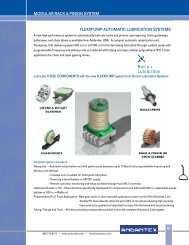
LUBRICATION RECOMMENDATIONS<br />
Proper and consistent lubrication is extremely important for rack and pinion drives. Proper<br />
lubrication for gears insures long life. The challenge with rack and pinion drives is getting<br />
lubrication to the components since there is no oil reservoir that the “gears” can sit in.<br />
To ensure consistent and uniform lubrication over time the use of an Automatic Lubrication<br />
system or a developed schedule of manual lubrication is needed. For consistent reliable<br />
application of lubricants we highly recommend the use of an Automatic Lubrication<br />
system. The following information is a guideline for automatic lubrication, and should be<br />
adjusted to the specific application.<br />
Automatic Lubricators 125 cm 3 & 475 cm 3<br />
ø79<br />
92.08<br />
160<br />
ø9.25 ø121<br />
105<br />
ø6.35<br />
142<br />
103 Ref.<br />
190<br />
156 Ref.<br />
Fig. Fig. 1 1<br />
ø69<br />
1 /4” NPT<br />
Fig. 2<br />
ø104<br />
1 /4” NPT<br />
1 /2” NPT (F) to 1 /4” NPT (M)<br />
Part Number Fig. Description<br />
A1119 Fig. 1 125 cm 3 Automatic lubricator, complete with mounting bracket contact cable,<br />
and filled with Klüber Structovis AHD synthetic grease.<br />
A1121 Fig. 2 475 cm 3 Automatic lubricator, complete with mounting bracket contact cable,<br />
and filled with Klüber Structovis AHD synthetic grease.<br />
Operating Principle<br />
The units operation is based on an<br />
electro-chemical reaction. When<br />
one or a combination of selector<br />
switches are turned on, the electrochemical<br />
reaction begins, where<br />
electrical energy is converted into<br />
nitrogen gas. A hermetically sealed<br />
bellows type chamber captures the<br />
gas created by the reaction. The<br />
resultant pressure, applied against<br />
a piston, causes the lubricant to be<br />
delivered to the lubrication point<br />
under constant pressure. The<br />
electrical current strength determines<br />
the amount of gas produced, and is<br />
directly related to the dispensing<br />
rate and the length of time the unit<br />
can operate. The quantity of grease<br />
supplied by the unit is adjustable,<br />
and can be matched to the<br />
application requirements, by setting<br />
the selector switches.<br />
800-713-6170 • www.andantex.com • info@andantex.com<br />
33
<strong>MODULAR</strong> <strong>RACK</strong> & <strong>PINION</strong> <strong>SYSTEM</strong><br />
General Information<br />
The units can be mounted in any position,<br />
and are provided with a contact cable for<br />
synchronization with machine operation. The<br />
lubricant dispensing rate can be adjusted during<br />
operation by simply adjusting the selector<br />
switches. The translucent housing allows for<br />
easy inspection of the lubricant level, and the<br />
units have an LED that can be set to flash every<br />
15 to 20 seconds indicating the system is in<br />
working order. The unit is rated for temperatures<br />
up to 130° F, and maximum pressure of 50 PSI.<br />
This unit is designed to feed a single point and<br />
is not intended as a multi point lubricator.<br />
The lubricator is supplied with a cover to<br />
protect against dirt, and moisture, and in all<br />
cases, the cover must be installed to ensure<br />
the intrinsic safety rating of the unit. The<br />
service life of the battery is 1 year.<br />
Lubrication Rate<br />
When using an electronic lubricator, and<br />
felt pinion to lubricate a rack and pinion<br />
drive the most favorable lubrication rate<br />
can be determined from the graph below.<br />
Starting Procedure<br />
Before running the rack and pinion drive,<br />
apply a film of lubricant to the entire length<br />
of rack and the pinion.<br />
On first installation, using a hand grease<br />
gun and the same type of lubricant, fill all<br />
lubrication lines and fittings. We<br />
recommend that you soak the felt pinion in<br />
the identical lubricant prior to installation.<br />
“Prestart” the unit by turning all switches<br />
to the “ON” position for 8 hours.<br />
“Prestarting” eliminates the time delay for<br />
dispensing lubricant to the application.<br />
Should you decide not to “prestart” the unit<br />
there will be a time delay before pressure<br />
builds in the unit and lubricant is dispensed.<br />
The time delay varies from 18 hours at the<br />
1M setting, to 240 hours at the 12M setting.<br />
After the allotted “prestart” period, turn all<br />
switches to the “OFF” position.<br />
Set the appropriate selection switches, for<br />
the applications required lubrication rate,<br />
to “ON”. Also turn the “LIGHT” switch to<br />
“ON”. The LED light will flash every 15 to 20<br />
seconds assuring that the system is working.<br />
Lubricant Recommendation<br />
Felt Pinion Lubrication: Klüber Structovis AHD<br />
Rack and Pinion lubrication rate for Felt Pinion<br />
34<br />
800-713-6170 • www.andantex.com • info@andantex.com
<strong>MODULAR</strong> <strong>RACK</strong> & <strong>PINION</strong> <strong>SYSTEM</strong><br />
Part Number Fig. Description<br />
Fig. 3<br />
A1118 Fig. 4 Lubrication line, including 6 feet of tubing, instant tube connectors, and adapter fitting.<br />
Fig. 5<br />
A1123<br />
Klüber Sutructovis AHD Synthetic grease 1 liter<br />
Note: Pre fill all lines and fittings with lubricant prior to starting the automatic lubrication system<br />
800-713-6170 • www.andantex.com • info@andantex.com<br />
35
<strong>MODULAR</strong> <strong>RACK</strong> & <strong>PINION</strong> <strong>SYSTEM</strong><br />
FELT <strong>PINION</strong> AND MOUNTING SHAFT FOR LUBRICATION <strong>SYSTEM</strong><br />
Felt Pinion<br />
Mounting Shaft<br />
Felt<br />
Pinion Tooth style L<br />
Number<br />
of teeth ØDo<br />
Mounting<br />
shaft L1 L2 ØD M L3 L4 ØD1<br />
230800 Circular p2 10 30 19.1 230 900 31 11 8 M4 8 13 20<br />
230810 Straight Mod. 1 10 20 20<br />
230801 Circular p5 12 15 23.87 230 901 33 13 12 M4 8 13 20<br />
230811 Straight Mod. 1.5 12 15 22.5<br />
230802 Circular p5 15 15 23.87 230 902 36 16 12 M4 8 13 20<br />
230812 Straight Mod. 2 15 15 30 230 903 36 16 15 M4 8 13 20<br />
230820 Helical Mod. 1.5 15 16 25.46<br />
230821 Helical Mod. 2 20 16 33.95 230 904 41 21 15 M4 8 13 20<br />
230803 Circular p7.5 20 15 35.8 230 905 41 21 20 M5 10 15 25<br />
230813 Straight Mod. 2.5 20 15 37.5<br />
230822 Helical Mod. 2.5 25 16 42.44 230 906 46 26 20 M5 10 15 25<br />
230814 Straight Mod. 3 25 15 45 230 907 46 26 25 M5 10 20 30<br />
230804 Circular p10 30 15 47.75 230 908 51.5 31 30 M5 10 20 40<br />
230815 Straight Mod. 4 30 15 60<br />
230823 Helical Mod. 3 30 16 50.93<br />
230805 Circular p12.5 40 15 59.68 230 909 61.5 41 40 M6 12 30 50<br />
230816 Straight Mod. 5 40 15 75<br />
230824 Helical Mod. 4 40 16 67.9<br />
230806 Circular p16 50 15 76.4 230 910 71.5 51 50 M6 12 30 60<br />
230817 Straight Mod. 6 50 15 90<br />
230825 Helical Mod. 5 50 16 84.88<br />
230807 Circular p20 60 16 105.68 230 911 81.5 61 50 M6 12 30 60<br />
230808 Circular p25 60 12 100.26<br />
230818 Straight Mod. 8 60 15 120<br />
230826 Helical Mod. 6 60 16 101.85<br />
230827 Helical Mod. 8 60 16 135.81<br />
230819 Straight Mod. 10 80 15 150.0 230 912 113 91 80 M10 20 50 95<br />
230828 Helical Mod. 10 90 16 169.72<br />
36<br />
800-713-6170 • www.andantex.com • info@andantex.com
<strong>MODULAR</strong> <strong>RACK</strong> & <strong>PINION</strong> <strong>SYSTEM</strong><br />
<strong>RACK</strong> & <strong>PINION</strong> INSTALLATION GUIDELINES<br />
The mounting and alignment of rack & pinion drives is critical to the performance and<br />
lifetime of the axis. Racks can be mounted in any position. In environments where debris<br />
is present (chips, sawdust, etc.) the rack should be mounted with the teeth facing down<br />
or covered to minimize contamination. It is recommended that a small right angle<br />
“ledge” be provided on the mounting surface to locate the rack on two faces. This makes<br />
it easier to accurately mount several pieces of rack in succession. We recommend using<br />
the predrilled holes in the rack as a guide for the tapped holes in the mounting surface<br />
in order to insure optimum alignment.<br />
The following instructions are meant<br />
to be general guidelines on how to<br />
achieve an accurate mounting of<br />
a rack & pinion drive:<br />
1. Mount and align the linear slides<br />
(rails) to the axis base.<br />
2. Measure the location of the rail in<br />
relation to the rack mounting surface<br />
with a dial indicator (see A.).<br />
A shoulder should be provided on<br />
the mounting surface to locate the<br />
back of the rack (see B.).<br />
The rack mounting surface tolerance<br />
will affect the contact pattern of the<br />
drive; the rack shoulder tolerance<br />
will affect the backlash of the drive.<br />
The more accurate these surfaces<br />
are, the better the axis will perform.<br />
3. Attach the first rack segment to the<br />
rack mounting surface. Measure the<br />
location of the rail in relation to the<br />
pitchline of the rack segment with<br />
a dial indicator (see diagram C.).<br />
To locate the pitchline of the rack,<br />
a pin (see table for size) is placed<br />
in-between the rack teeth and an<br />
over-pin tolerance is measured:<br />
Rack Module<br />
Module 2.0<br />
Module 3.0<br />
Module 4.0<br />
Module 5.0<br />
Module 6.0<br />
Module 8.0<br />
Module 10.0<br />
Pin Size<br />
Ø3.5 mm (Ø0.138”)<br />
Ø5.0 mm (Ø0.197”)<br />
Ø7.0 mm (Ø0.276”)<br />
Ø8.0 mm (Ø0.354”)<br />
Ø10.0 mm (Ø0.394”)<br />
Ø12.0 mm (Ø0.472”)<br />
Ø18.0 mm (Ø0.709”)<br />
If the tolerances are found to be<br />
high, the rack should be shimmed<br />
accordingly and the rack pitchline<br />
parallelism should be checked again<br />
(step #3).<br />
A.<br />
Rack Mounting<br />
Surface Tolerance<br />
B.<br />
Rack Shoulder Tolerance<br />
C.<br />
Over-pin Tolerance<br />
800-713-6170 • www.andantex.com • info@andantex.com<br />
37
<strong>MODULAR</strong> <strong>RACK</strong> & <strong>PINION</strong> <strong>SYSTEM</strong><br />
Once the desired tolerance is reached, attach the rack to the machine frame using Class<br />
12.9 socket head capscrews tightened to the torque values shown in the table below:<br />
Screw Size M6 M8 M12 M16 M20 M30<br />
Tightening<br />
Torque 10 (7) 26 (19) 89 (66) 215 (159) 420 (310) 1450 (1070)<br />
NM (LB. Ft.)<br />
4. Attach the next rack segment to the<br />
rack mounting surface. A companion<br />
rack should be used to properly<br />
space the teeth in-between rack<br />
segments.<br />
Again measure the location from the<br />
rail in relation to the rack segment<br />
(as in step #3). Continue mounting the<br />
rack segments for the entire travel<br />
length using the same procedure.<br />
5. Mount the pinion/gearbox to the rail<br />
carriage. Make sure the pinion<br />
engages the total face width of the<br />
rack. Check the alignment of the<br />
rack & pinion by marking or “bluing”<br />
the pinion teeth with a high spot<br />
paste (Dykem) and slowly running<br />
the axis in both directions. This will<br />
show the tooth contact pattern<br />
between the rack & pinion; a<br />
contact pattern across the majority<br />
of the tooth flank on both the rack<br />
and pinion is desired. If the contact<br />
pattern is shifted to one side of<br />
the tooth flanks, some form of<br />
misalignment is present.<br />
Pinion not perpendicular<br />
Pinion not parallel<br />
6. Measure the linear backlash between<br />
the rack & pinion along the entire<br />
axis travel length. A general guide for<br />
minimum backlash is shown below:<br />
Rack Quality<br />
Minimum Backlash<br />
Induction Hardened 0.20 mm (0.008”)<br />
Quenched & Tempered 0.10 mm (0.004”)<br />
Hardened & Ground 0.05 mm (0.002”)<br />
7. Run the pinion/gearbox through the<br />
entire rack travel length to check<br />
for any problems, such as binding<br />
or excessive noise. If either is<br />
found, return to step #3.<br />
8. Drill dowel pin holes into the rack<br />
mounting surface using the pilot<br />
holes in racks. Place dowel pins<br />
in the holes (two for each rack<br />
segment).<br />
Correct Mesh<br />
Pinion not perpendicular<br />
Pinion not parallel<br />
<strong>Inc</strong>orrect center distance<br />
38<br />
800-713-6170 • www.andantex.com • info@andantex.com
1705 Valley Road,<br />
Wanamassa, NJ 07712<br />
800/713-6170<br />
Fax 732/493-2949<br />
E-mail info@andantex.com<br />
www.andantex.com