MODULAR RACK & PINION SYSTEM - Andantex USA Inc.
MODULAR RACK & PINION SYSTEM - Andantex USA Inc.
MODULAR RACK & PINION SYSTEM - Andantex USA Inc.

You also want an ePaper? Increase the reach of your titles
YUMPU automatically turns print PDFs into web optimized ePapers that Google loves.
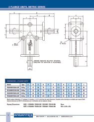
<strong>MODULAR</strong> <strong>RACK</strong> & <strong>PINION</strong> <strong>SYSTEM</strong><br />
Once the desired tolerance is reached, attach the rack to the machine frame using Class<br />
12.9 socket head capscrews tightened to the torque values shown in the table below:<br />
Screw Size M6 M8 M12 M16 M20 M30<br />
Tightening<br />
Torque 10 (7) 26 (19) 89 (66) 215 (159) 420 (310) 1450 (1070)<br />
NM (LB. Ft.)<br />
4. Attach the next rack segment to the<br />
rack mounting surface. A companion<br />
rack should be used to properly<br />
space the teeth in-between rack<br />
segments.<br />
Again measure the location from the<br />
rail in relation to the rack segment<br />
(as in step #3). Continue mounting the<br />
rack segments for the entire travel<br />
length using the same procedure.<br />
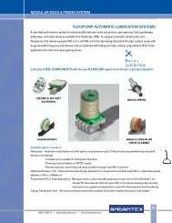
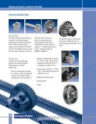
5. Mount the pinion/gearbox to the rail<br />
carriage. Make sure the pinion<br />
engages the total face width of the<br />
rack. Check the alignment of the<br />
rack & pinion by marking or “bluing”<br />
the pinion teeth with a high spot<br />
paste (Dykem) and slowly running<br />
the axis in both directions. This will<br />
show the tooth contact pattern<br />
between the rack & pinion; a<br />
contact pattern across the majority<br />
of the tooth flank on both the rack<br />
and pinion is desired. If the contact<br />
pattern is shifted to one side of<br />
the tooth flanks, some form of<br />
misalignment is present.<br />
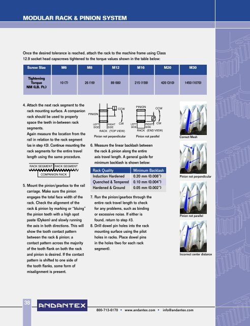
Pinion not perpendicular<br />
Pinion not parallel<br />
6. Measure the linear backlash between<br />
the rack & pinion along the entire<br />
axis travel length. A general guide for<br />
minimum backlash is shown below:<br />
Rack Quality<br />
Minimum Backlash<br />
Induction Hardened 0.20 mm (0.008”)<br />
Quenched & Tempered 0.10 mm (0.004”)<br />
Hardened & Ground 0.05 mm (0.002”)<br />
7. Run the pinion/gearbox through the<br />
entire rack travel length to check<br />
for any problems, such as binding<br />
or excessive noise. If either is<br />
found, return to step #3.<br />
8. Drill dowel pin holes into the rack<br />
mounting surface using the pilot<br />
holes in racks. Place dowel pins<br />
in the holes (two for each rack<br />
segment).<br />
Correct Mesh<br />
Pinion not perpendicular<br />
Pinion not parallel<br />
<strong>Inc</strong>orrect center distance<br />
38<br />
800-713-6170 • www.andantex.com • info@andantex.com