Switch-Mode and Uninterruptible Power Supplies, Electronic Fuses ...
Switch-Mode and Uninterruptible Power Supplies, Electronic Fuses ...
Switch-Mode and Uninterruptible Power Supplies, Electronic Fuses ...

You also want an ePaper? Increase the reach of your titles
YUMPU automatically turns print PDFs into web optimized ePapers that Google loves.
Glossary<br />
Glossary/Technical appendix<br />
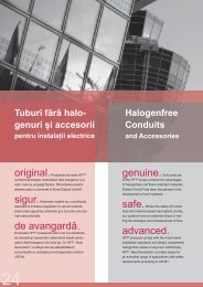
IU characteristic curve<br />
The IU characteristic curve is a special output characteristic curve that<br />
protects power supply units from overloads <strong>and</strong> short circuits. It offers the best<br />
performance with regards to overload <strong>and</strong> short circuit capabilities. A current<br />
limit is activated at a specific current level (for example, 110 or 120 % on the<br />
nominal rating). As the load continues to increase, the output voltage is reduced<br />
according to the current limit curve until it reaches a level approaching zero<br />
volts. Thus a pulsating mode of operations is avoided for short-term overloads.<br />
Large capacitive loads or motors are brought back up along the slope of the<br />
current-limit characteristic curve. After a short circuit or overload is fixed, the IU<br />
characteristic curve offers the advantage of immediately returning to the normal<br />
voltage control mechanism. The full output voltage is then immediately available.<br />
The IU characteristic curve is becoming the established st<strong>and</strong>ard for modern<br />
power supplies. Additional variants are available which pertain to the peak<br />
current capacity <strong>and</strong> the slope of the current-limit characteristic curve.<br />
U A<br />
U<br />
INominal<br />
ILimit<br />
I<br />
M<br />
Mains harmonics<br />
Mains system types<br />
<strong>Power</strong> supplies can experience harmonics caused by mains rectification on the<br />
input side. These harmonics are multiples of the mains frequencies. Existing<br />
st<strong>and</strong>ards define specific limit values since such harmonics can significantly<br />
lower the mains quality.<br />
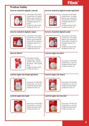
This refers to the types of mains supply systems. Systems differ in their method<br />
of earthing <strong>and</strong> the implementation of the phase wire, PE wire <strong>and</strong> central-point<br />
wire. Common mains systems include the TN, IT <strong>and</strong> TT networks. The individual<br />
mains types can also differ in their voltage levels <strong>and</strong> frequencies.<br />
PRO-M<br />
PRO-M<br />
PRO-M<br />
PRO-M<br />
L N PE<br />
TN-S Mains<br />
L1<br />
L2<br />
L3<br />
N<br />
PE<br />
TN-C Mains<br />
L1<br />
L2<br />
L3<br />
PEN<br />
L N PE<br />
TT Mains<br />
L1<br />
L2<br />
L3<br />
N<br />
L N PE<br />
IT Mains<br />
L1<br />
L2<br />
L3<br />
N<br />
L N PE<br />
W<br />
MTBF (mean time between failure)<br />
The MTBF is a statistical value that specifies the probability that a product will<br />
fail. It is typically specified in hours <strong>and</strong> normally assumes a temperature of<br />
25 °C. The probability of failure depends largely on the ambient surroundings.<br />
The key variables are the type of load <strong>and</strong> the ambient temperature.<br />
W.10 1366860000 – 2013