Vane Axial Fans - Greenheck
Vane Axial Fans - Greenheck
Vane Axial Fans - Greenheck

You also want an ePaper? Increase the reach of your titles
YUMPU automatically turns print PDFs into web optimized ePapers that Google loves.
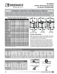
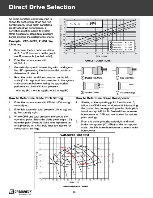
Direct Drive Selection<br />
An outlet condition correction chart is<br />
shown for each group of fan and hub<br />
combinations. Since outlet conditions<br />
greatly affect fan performance, a<br />
correction must be added to system<br />
static pressure to obtain total pressure<br />
before entering the performance charts.<br />
Example: VAD-54F26, 41,000 cfm,<br />
1.6 in. wg<br />
1. Determine the fan outlet condition:<br />
0.02<br />
A, B, C or D as shown on the graph,<br />
15<br />
use B in example (ducted outlet).<br />
2. Enter the bottom scale with<br />
41,000 cfm.<br />
3. Go vertically up until intersecting with the diagonal<br />
line “B” representing the ducted outlet condition<br />
determined in step 1.<br />
4. Read the outlet condition correction on the left<br />
scale (0.4 in. wg). Add this correction to the system<br />
static pressure before entering the appropriate<br />
performance chart with total pressure.<br />
1.6 in. wg (P s ) + 0.4 in. wg (P c ) = 2.0 in. wg (P t )<br />
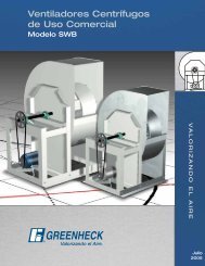
How to Determine Blade Pitch Setting<br />
Pressure Correction: Pc (in. wg)<br />
10<br />
6<br />
4<br />
2<br />
1<br />
0.6<br />
0.4<br />
0.2<br />
0.1<br />
0.06<br />
0.04<br />
1. Enter the bottom scale with CFM (41,000) and go<br />
vertically up.<br />
2. Enter left scale with total pressure (2.0 in. wg) and<br />
go horizontally right.<br />
3. Where CFM and total pressure intersect is the<br />
operating point. Select the blade pitch angle (15°)<br />
from this point (Point A). Solid lines represent fan<br />
total pressure vs. CFM. Bold lines are labeled for<br />
various pitch settings.<br />
3.50<br />
CFM<br />
Pt = Ps + Pc Pc = ( ) 2<br />
K<br />
D<br />
C<br />
B<br />
A<br />
A<br />
B<br />
C<br />
D<br />
Ducted w/cone<br />
Ducted Outlet<br />
Free w/cone<br />
Free Discharge<br />
K = 92,180<br />
K = 66,080<br />
K = 79,280<br />
K = 50,740<br />
20 30 40 50 60 70 80 90 100 150<br />
CFM x 1,000<br />
VAD-54F26 870 RPM<br />
OUTLET CONDITIONS<br />
A Ducted with Cone C Free with Cone<br />
B Ducted Outlet D Free Discharge<br />
How to Determine Brake Horsepower<br />
1. Starting at the operating point found in step 3,<br />
follow the CFM line up or down until intersecting<br />
the dashed line corresponding to the blade pitch<br />
found in step 3 (Point B). Dashed lines represent<br />
horsepower vs. CFM and are labeled for various<br />
pitch settings.<br />
2. From this point go horizontally right and read<br />
brake horsepower (17.2 Bhp) on the horsepower<br />
scale. Use this brake horsepower to select motor<br />
horsepower.<br />
3.00<br />
40<br />
2.50<br />
Point A<br />
25°<br />
30°<br />
30<br />
Total Pressure (in. wg)<br />
2.00<br />
1.50<br />
1.00<br />
0°<br />
5°<br />
10°<br />
15°<br />
20°<br />
75%<br />
70%<br />
Point B<br />
65%<br />
60%<br />
20°<br />
25°<br />
30°<br />
20<br />
10<br />
0<br />
Horsepower<br />
15°<br />
0.50<br />
10°<br />
5°<br />
0°<br />
0.00<br />
0 5 10 15 20 25 30 35 40 45 50 55 60 65 70 75 80 85 90<br />
CFM x 1,000<br />
PERFORMANCE CHART<br />
®<br />
20