BoonDocker Nitrous System Installation Instructions for Kawasaki ...
BoonDocker Nitrous System Installation Instructions for Kawasaki ...
BoonDocker Nitrous System Installation Instructions for Kawasaki ...

You also want an ePaper? Increase the reach of your titles
YUMPU automatically turns print PDFs into web optimized ePapers that Google loves.
<strong>BoonDocker</strong> <strong>Nitrous</strong> <strong>System</strong> <strong>Installation</strong> <strong>Instructions</strong><br />
<strong>for</strong> <strong>Kawasaki</strong> KFX-700 ATV<br />
Be<strong>for</strong>e you begin, please read the instructions below and check kit contents<br />
<strong>Nitrous</strong> Kit Contents:<br />
1 – <strong>Nitrous</strong> Manifold with fittings installed<br />
1 – <strong>Nitrous</strong> Bottle with 4AN fitting<br />
2 – bottle clamps<br />
1 – 4’ high pressure braided hose<br />
1 – 12” length of 1/8” black nylon hose<br />
1 – solenoid<br />
1 – solenoid holding bracket<br />
1 – 1/8” NPT compression fitting <strong>for</strong> solenoid<br />
1 – 1/8” NPT to 4AN adapter <strong>for</strong> solenoid<br />
1 – pushbutton switch<br />
2 – mounting clamps <strong>for</strong> pushbutton switch (1 bolt style,<br />
1 crimp style)<br />
1 – rectifier<br />
4 – misc. electrical connectors<br />
2 - orificed cup plugs (¼” and 3/16”)<br />
1- 12” length of ¼” tubing<br />
1-1/4 x1/4x1/4 plastic T<br />
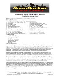
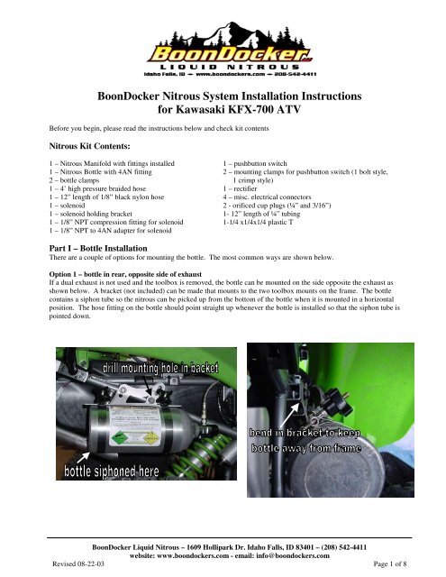
Part I – Bottle <strong>Installation</strong><br />
There are a couple of options <strong>for</strong> mounting the bottle. The most common ways are shown below.<br />
Option 1 – bottle in rear, opposite side of exhaust<br />
If a dual exhaust is not used and the toolbox is removed, the bottle can be mounted on the side opposite the exhaust as<br />
shown below. A bracket (not included) can be made that mounts to the two toolbox mounts on the frame. The bottle<br />
contains a siphon tube so the nitrous can be picked up from the bottom of the bottle when it is mounted in a horizontal<br />
position. The hose fitting on the bottle should point straight up whenever the bottle is installed so that the siphon tube is<br />
pointed down.<br />
<strong>BoonDocker</strong> Liquid <strong>Nitrous</strong> – 1609 Hollipark Dr. Idaho Falls, ID 83401 – (208) 542-4411<br />
website: www.boondockers.com - email: info@boondockers.com<br />
Revised 08-22-03 Page 1 of 8
(Part I – Bottle <strong>Installation</strong> - Cont.)<br />
Option 2 – bottle across rear bumper<br />
A simple bottle bracket (not included) can be mounted to the two bolts that hold the rear skidplate in place as shown below.<br />
The rear taillight will need to be trimmed to clear the bottle.<br />
Part II – <strong>Nitrous</strong> Manifold <strong>Installation</strong><br />
1. The <strong>Nitrous</strong> Manifold will be installed on top of the airfilter lid. Use the template below on the next page as a guide to<br />
drill the three holes using ½” and 5/16” drill bits. Center the nitrous manifold so it is directly between the two<br />
carburetor intakes. The airbox lid can be flattened with a hammer so the nitrous manifold body can sit flat on the lid.<br />
2. Disassemble the nitrous manifold by first unscrewing the aluminum bolt.<br />
Carefully separate the plastic half from the aluminum body as show in<br />
the picture. Be careful not to allow debris inside the plastic piece or the<br />
aluminum body while the manifold is disassembled.<br />
3. Install the manifold with the plastic half inside the filter and the<br />
aluminum half on the outside. Push the two halves together then thread<br />
the aluminum bolt in so the two halves are tight against the filter (be sure<br />
the o-rings are pushed on the aluminum body be<strong>for</strong>e tightening the bolt).<br />
Tighten to 80-90 in-lbs.<br />
4. Be sure the manifold body seals against the back of the filter and that<br />
there are no air leaks. Use silicon or thick grease if necessary.<br />
<strong>BoonDocker</strong> Liquid <strong>Nitrous</strong> – 1609 Hollipark Dr. Idaho Falls, ID 83401 – (208) 542-4411<br />
website: www.boondockers.com - email: info@boondockers.com<br />
Revised 08-22-03 Page 2 of 8
Part III – Solenoid / Hose <strong>Installation</strong><br />
1. Be<strong>for</strong>e installing the following fittings, apply a thread<br />
sealant or teflon tape to the threads – be careful not to<br />
contaminate the insides of these fittings.<br />
a. Connect the 1/8 NPT - 4AN fitting to the side of<br />
the solenoid marked “IN”.<br />
b. Connect the brass compression fitting to the side<br />
of the solenoid marked “OUT”.<br />
2. Locate the solenoid on the airbox as shown in the picture below.<br />
The 1/8” black nylon hose going to the manifold and the highpressure<br />
hose from the bottle needs to easily reach the solenoid<br />
with no sharp bends.<br />
3. Use the padded strap to secure the solenoid to the airbox.<br />
4. Connect the 1/8” black nylon line from the brass compression fitting on the solenoid to the brass compression fitting on<br />
the nitrous manifold by drilling a hole in the<br />
airbox and routing the line through it. Do not<br />
make sharp bends in the line and keep it away<br />
from sharp objects. Note – do not over tighten<br />
the compression fittings!<br />
5. Connect the high-pressure braided hose from<br />
the bottle to the solenoid, keeping it away from<br />
the exhaust, and secure it with zip-ties.<br />
Manifold Cutout Template<br />
<strong>BoonDocker</strong> Liquid <strong>Nitrous</strong> – 1609 Hollipark Dr. Idaho Falls, ID 83401 – (208) 542-4411<br />
website: www.boondockers.com - email: info@boondockers.com<br />
Revised 08-22-03 Page 3 of 8
Part IV - Carb Vent to <strong>Nitrous</strong> Manifold <strong>Installation</strong><br />
The nitrous manifold must be able to pressurize the carb float<br />
bowl and the carb vent lines must be able to drain if fuel gets<br />
trapped in the lines. Refer to the pictures and drawings as you<br />
read the steps below.<br />
1. Disconnect the existing vent line inside the airbox that<br />
connects the Carb Vent to the Outside Vent.<br />
2. Connect a short vent line from the carb vent (middle of carb<br />
throats) to a plastic Tee.<br />
3. Connect a short vent line from the Tee to the Outside Vent<br />
fitting. Be<strong>for</strong>e connecting to the Outside Vent fitting, insert<br />
a ¼” orificed cup plug.<br />
4. Drill a ¼” hole into the filter cover <strong>for</strong> the vent line that will go to<br />
the nitrous manifold (see picture).<br />
5. Connect the other side of the Tee to a vent line that will go through<br />
the hole in the airfilter lid to the nitrous manifold. Use silicon to<br />
seal the outside of the vent line to the lid.<br />
6. Find the carb drain line on the left side of the ATV. Remove<br />
the check valve and insert the 3/16” orificed cup plug. Reinstall<br />
the check valve.<br />
carb vent – connect to<br />
<strong>Nitrous</strong> Manifold<br />
nitrous manifold<br />
carb<br />
carb<br />
Tee – insert<br />
inside airbox<br />
Insert ¼” orificed<br />
cup plug inside<br />
airbox<br />
Insert 3/16”<br />
orificed cup plug<br />
be<strong>for</strong>e check valve<br />
<strong>BoonDocker</strong> Liquid <strong>Nitrous</strong> – 1609 Hollipark Dr. Idaho Falls, ID 83401 – (208) 542-4411<br />
website: www.boondockers.com - email: info@boondockers.com<br />
Revised 08-22-03 Page 4 of 8
Part V – Push-Button <strong>Installation</strong><br />
If the supplied pushbutton is used (instead of the existing “Override: button – see next<br />
section), the button can either be mounted directly on the left handgrip or the controls can<br />
be pushed over and the button can be mounted on the handlebar. There are two clamps in<br />
the kit. The one with the screw is used if the button needs to be mounted to the<br />
handlebar. Directions <strong>for</strong> mounting the button directly to the handgrip using the crimp-on<br />
clamp are shown below:<br />
1. Using pliers, bend a hook into one end of the clamp.<br />
2. Connect the clamp to the button as shown. Fit the hooked part of the clamp to the<br />
button so the straight part of the clamp is not connected.<br />
3. Put the button on the left handlebar. With a pen, mark on the clamp where the<br />
mounting hole on the button and the clamp meet.<br />
4. Remove the clamp and cut it approximately ¼” to 3/8” away from the mark. Bend this<br />
end with pliers so it is similar to the other hooked end.<br />
5. Put the button and clamp back on the handlebar. Tighten the clamp with sidecutters so<br />
it is just snug. Do not overtighten.<br />
6. The button should appear as shown in the picture.<br />
<strong>BoonDocker</strong> Liquid <strong>Nitrous</strong> – 1609 Hollipark Dr. Idaho Falls, ID 83401 – (208) 542-4411<br />
website: www.boondockers.com - email: info@boondockers.com<br />
Revised 08-22-03 Page 5 of 8
Part VI – Electrical <strong>Installation</strong><br />
A. Using the supplied push-button<br />
Wire the connections according to the diagram below. Use a 12V supply that is only<br />
on when the ignition key is turned on and the kill switch is in the “run” position. We<br />
still recommend using the rectifier even if the system has a battery – the diodes in the<br />
rectifier absorb the large current spike produced by the solenoid when the button<br />
breaks the connection (this prevents a spark). Even if a DC voltage is used, you must<br />
still connect the voltage supply to the two AC terminals.<br />
Most rectifiers are labeled on the side “+”, “AC”, “-”, “AC” (see picture). If the<br />
rectifier is not labeled, see the picture below.<br />
12V<br />
power<br />
handlebar<br />
switch<br />
+<br />
AC<br />
Rectifier<br />
_<br />
rectifier markings on the side<br />
Ground wire<br />
AC<br />
Solenoid<br />
Note: + and –<br />
connections can<br />
be wired either<br />
way<br />
For the KXF 700 the Yellow/Red wire from the ignition is +12 and the Black/Yellow<br />
wire is Ground, or a good contact to the chassis (near the fuel switch) can be used <strong>for</strong><br />
Ground.<br />
rectifier terminals<br />
B. Using the existing “Override” button and a toggle switch – BE CAREFUL!<br />
The Override button can be used with a toggle switch so it can be used as the<br />
nitrous button with the switch in one position, or it can function as the<br />
Override button with the switch in the other position.<br />
There is a two-wire pair (yellow/white and brown wires) that the Override<br />
button controls. The yellow/white wire connects to a yellow/black wire –<br />
break this connection and wire the toggle switch according to the diagram<br />
below:<br />
12V<br />
power<br />
Brown<br />
wire<br />
existing<br />
wiring<br />
Override<br />
switch<br />
Toggle<br />
switch<br />
(SPDT)<br />
Yellow/white<br />
wire<br />
Yellow/black<br />
wire – back to<br />
original wiring<br />
+<br />
AC<br />
Rectifier<br />
AC<br />
_<br />
Ground<br />
wire<br />
Solenoid<br />
Note: + and –<br />
connections can<br />
be wired either<br />
way<br />
<strong>BoonDocker</strong> Liquid <strong>Nitrous</strong> – 1609 Hollipark Dr. Idaho Falls, ID 83401 – (208) 542-4411<br />
website: www.boondockers.com - email: info@boondockers.com<br />
Revised 08-22-03 Page 6 of 8
Part VII – Tuning <strong>Instructions</strong><br />
A. Carb Jetting:<br />
Because the nitrous manifold changes the carb venting from atmosphere to inside the airbox, the main jet size will need to<br />
be increased. When a large volume of air flows through the airbox, a negative pressure will develop inside the airbox<br />
because of the restrictions in the airbox and filter. This negative pressure will cause the engine to run too lean unless the<br />
main jet size is increased.<br />
The stock KFX700 airbox requires a large increase in the main jet size. For example, if the original jetting is 138/140, a<br />
jump to 165/167.5 may be required. Make sure the carb jetting is correct be<strong>for</strong>e proceeding with the tuning instructions.<br />
B. Important Notes be<strong>for</strong>e using <strong>Nitrous</strong>:<br />
1. We strongly recommend using high-octane fuel (at least 94 <strong>for</strong> most stock motors, more <strong>for</strong> modified motors).<br />
We have found that race fuel or Boondocker race fuel concentrate mixed with premium gas can provide the<br />
necessary octane.<br />
2. We also recommend using one size colder spark plug (higher number = colder). In some cases decreasing the<br />
spark plug gap to 0.020” achieves best results.<br />
3. Be sure to use filtered nitrous – always use a filter when filling your bottle!<br />
C. Startup & Leak Test Procedure<br />
The rider must do the following steps every time the bottle is turned on and be<strong>for</strong>e doing the fuel adjustment procedure.<br />
1. With the engine off, open the bottle valve and check <strong>for</strong> leaks. Shut the bottle valve off. With the valve shut, the<br />
hose will still have pressure in it.<br />
2. With pressure in the hose and the bottle valve closed, start the engine. Check to make sure the solenoid does not<br />
discharge hose pressure.<br />
3. With the engine running (be ready to shut down engine if necessary), open the bottle valve. Push the nitrous button<br />
<strong>for</strong> about one second or less. Engine rpm should increase if the nitrous system is functioning properly.<br />
<strong>BoonDocker</strong> Liquid <strong>Nitrous</strong> – 1609 Hollipark Dr. Idaho Falls, ID 83401 – (208) 542-4411<br />
website: www.boondockers.com - email: info@boondockers.com<br />
Revised 08-22-03 Page 7 of 8
D. <strong>Nitrous</strong> Manifold Fuel Adjustment Procedure<br />
The steps below should be done with a full nitrous bottle that is at the proper operating temperature (70-90deg F). Make<br />
sure the engine is at normal operating temperature. Do not exceed 2 seconds of nitrous use until the fuel adjustment is<br />
complete and correct.<br />
This adjustment process should only be per<strong>for</strong>med by an experienced tuner. If you are not an experienced tuner, find<br />
someone who is. Remember, safety first!<br />
Warning: Only adjust the fuel mixture screws according to the steps below. The factory setting is fully closed. We<br />
recommend starting with the adjustment screw turned out 2 full turns.<br />
1. Run the vehicle in an open area at full throttle and apply nitrous <strong>for</strong> 1 or 2 seconds. Note engine power and rpms when<br />
the button is pushed.<br />
2. Enrichen the mixture by turning the nitrous manifold adjustment screw in (clockwise) 1/2 turn. Run nitrous <strong>for</strong> 1 or 2<br />
seconds again and note power and rpm difference. If no power loss is noted, repeat step 2 until a loss is noted. A<br />
power loss indicates you are rich enough (be sure!) - go to step 3.<br />
3. To find where the mixture starts to become too lean, turn the nitrous manifold adjustment screw out (counterclockwise)<br />
1/2 turn and note power. A power increase should be noted. Turn nitrous manifold adjustment out 1/2 turn and<br />
compare to previous run. If no power increase is noted, go to step 4. If power increase is noted, repeat step 3 until no<br />
power increase is noted. Use extreme caution - you can go too lean!<br />
4. For the final setting, turn the nitrous manifold adjustment screw back in (clockwise) 1/2 turn.<br />
5. After this adjustment is made, if the engine does not run perfectly smooth when using nitrous, do not use it! If the<br />
exhaust note does not sound clean, the cause is likely detonation which can quickly destroy the engine. Either use<br />
higher-octane fuel or reduce the engine’s compression be<strong>for</strong>e using nitrous again.<br />
Part VIII – Warranty, Terms & Conditions<br />
Returned Goods – No merchandise will be accepted without prior approval. A RMA number (Return Merchandise<br />
Authorization) provided by Boondocker is required be<strong>for</strong>e a return will be accepted. A 20% handling and restocking<br />
charge will be applied to returned merchandise. No unauthorized returns will be accepted.<br />
Limited Warranty – Boondocker warrants its product to the original purchaser against workmanship defects <strong>for</strong> a period<br />
of 90 days, commencing from the date of product delivery to the Consumer.<br />
Maximum Liability – The maximum liability of Boondocker in connection with this warranty shall not under any<br />
circumstances exceed the price of the product claimed to be defective.<br />
<strong>BoonDocker</strong> Liquid <strong>Nitrous</strong> – 1609 Hollipark Dr. Idaho Falls, ID 83401 – (208) 542-4411<br />
website: www.boondockers.com - email: info@boondockers.com<br />
Revised 08-22-03 Page 8 of 8