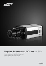
High Resolution D/N IR Dome Camera SIR ... - Balter Security
High Resolution D/N IR Dome Camera SIR ... - Balter Security
High Resolution D/N IR Dome Camera SIR ... - Balter Security

Create successful ePaper yourself
Turn your PDF publications into a flip-book with our unique Google optimized e-Paper software.
Installation<br />
Installation<br />
Installation<br />
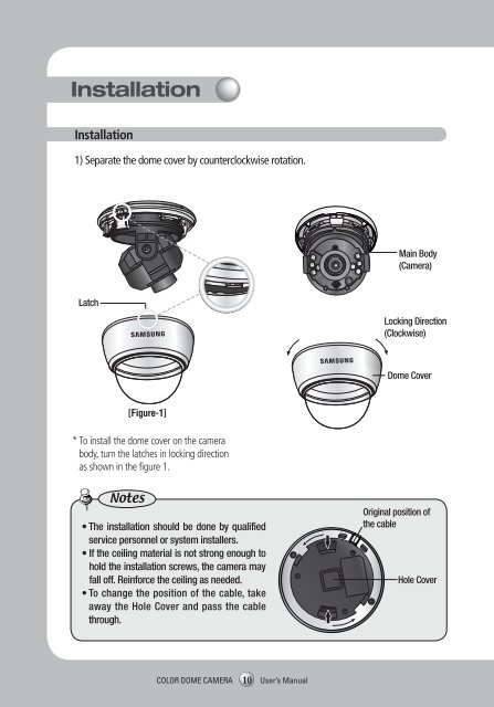
1) Separate the dome cover by counterclockwise rotation.<br />
Latch<br />
Main Body<br />
(<strong>Camera</strong>)<br />
Locking Direction<br />
(Clockwise)<br />
When using the Ceiling bracket<br />
Ceiling bracket<br />
M4 tapping<br />
screw (provided)<br />
An arrow for installing<br />
directions<br />
1) Hold the ceiling bracket (located where the arrow<br />
points to) and separate it from the main body of<br />
the camera by rotating it counterclockwise.<br />
(refer to the picture in 'Notes' on page 10)<br />
2) Adjust the camera lens to face the area to be<br />
monitored and fix the main body and the dome<br />
cover by aligning the grooves and rotating the<br />
body clockwise.<br />
* To install the dome cover on the camera<br />
body, turn the latches in locking direction<br />
as shown in the figure 1.<br />
Notes<br />
[Figure-1]<br />
• The installation should be done by qualified<br />
service personnel or system installers.<br />
• If the ceiling material is not strong enough to<br />
hold the installation screws, the camera may<br />
fall off. Reinforce the ceiling as needed.<br />
• To change the position of the cable, take<br />
away the Hole Cover and pass the cable<br />
through.<br />
<strong>Dome</strong> Cover<br />
Original position of<br />
the cable<br />
Hole Cover<br />
Unlocking<br />
direction<br />
<strong>Dome</strong> Cover<br />
Notes<br />
Locking direction<br />
M4<br />
tapping<br />
screw<br />
[Figure-2]<br />
• If you want to install the camera with the ceiling bracket combined, fix it using two M4<br />
tapping screws at the side of the main body(refer to the [Figure-2] on page 11)<br />
Pan Base<br />
fixation<br />
screw<br />
COLOR DOME CAMERA<br />
10 User’s Manual<br />
COLOR DOME CAMERA 11 User’s Manual