PhotoMOS with Short Circuit Protection - Panasonic Electric Works ...
PhotoMOS with Short Circuit Protection - Panasonic Electric Works ...
PhotoMOS with Short Circuit Protection - Panasonic Electric Works ...

You also want an ePaper? Increase the reach of your titles
YUMPU automatically turns print PDFs into web optimized ePapers that Google loves.
Application Note 026<br />
<strong>PhotoMOS</strong> <strong>with</strong> <strong>Short</strong> <strong>Circuit</strong> <strong>Protection</strong><br />
(Non Latch Type)<br />
‘Small size, reliability and low power consumption’<br />
are requirements for components used to switch<br />
signal outputs in sensors, control units or on<br />
measurement cards. An important function is the<br />
galvanic isolation of sensitive electronics from<br />
possible disturbances on the output side, e.g.<br />
voltage peaks or overcurrents, which can arise due<br />
to short circuits or improper use. The new short<br />
circuit protected <strong>PhotoMOS</strong> family from <strong>Panasonic</strong><br />
<strong>Electric</strong> <strong>Works</strong> is optimally prepared to meet these<br />
challenges. It ideally combines high switching<br />
speed <strong>with</strong> low control current and reliable<br />
overcurrent protection. The internal structure of a<br />
<strong>PhotoMOS</strong> relay and the protective function is<br />
described in detail below.<br />
The internal circuit of a <strong>PhotoMOS</strong> relay can be<br />
illustrated easily: on the input side of the switching<br />
element a light emitting diode is located. If a current<br />
flows through the LED it starts emitting light. This<br />
light is converted to a photo voltage by solar cells<br />
located at least 0.4 mm away. This photoelectric<br />
voltage drives the gate of two interconnected<br />
DMOSFET. This is the principle structure of every<br />
<strong>PhotoMOS</strong> relay, which is available in different<br />
packages (SSOP, SOP, DIL or SIL).<br />
However, <strong>PhotoMOS</strong> relays are continuously being<br />
developed further. <strong>Panasonic</strong> <strong>Electric</strong> <strong>Works</strong> is<br />
extending its product catalogue by enhancing the<br />
standard types of <strong>PhotoMOS</strong> relays <strong>with</strong> a<br />
protective element. The protective circuit is located<br />
on the output side of the component and recognizes<br />
inadmissibly high currents. The advantage of the<br />
protective feature is twofold: the DMOSFET on the<br />
output side and the load circuit is protected against<br />
an overcurrent. As soon as a dangerous load<br />
current arises, it is recognized by the protective unit<br />
and a counter measure is introduced.<br />
The current limited type recognizes a transient<br />
overcurrent and limits it to a less critical value. After<br />
applying an input current the load circuit is<br />
conductible (typical 0.55 Ω) and a current flows<br />
through the load. In case of an error this current<br />
increases and is detected by the protective circuit.<br />
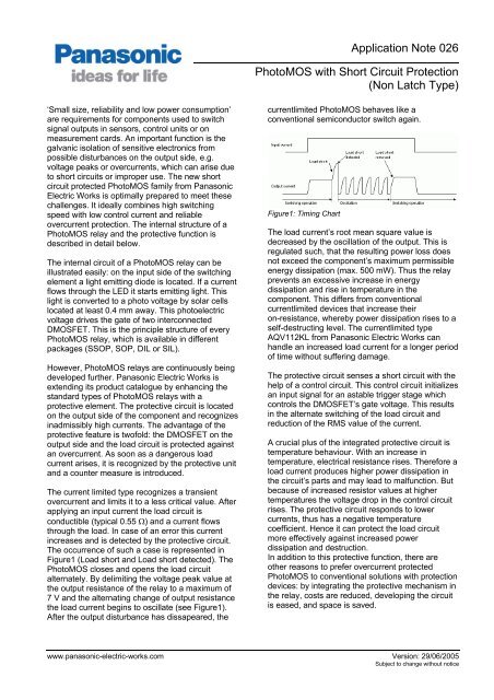
The occurrence of such a case is represented in<br />
Figure1 (Load short and Load short detected). The<br />
<strong>PhotoMOS</strong> closes and opens the load circuit<br />
alternately. By delimiting the voltage peak value at<br />
the output resistance of the relay to a maximum of<br />
7 V and the alternating change of output resistance<br />
the load current begins to oscillate (see Figure1).<br />
After the output disturbance has dissapeared, the<br />
currentlimited <strong>PhotoMOS</strong> behaves like a<br />
conventional semiconductor switch again.<br />
Figure1: Timing Chart<br />
The load current’s root mean square value is<br />
decreased by the oscillation of the output. This is<br />
regulated such, that the resulting power loss does<br />
not exceed the component’s maximum permissible<br />
energy dissipation (max. 500 mW). Thus the relay<br />
prevents an excessive increase in energy<br />
dissipation and rise in temperature in the<br />
component. This differs from conventional<br />
currentlimited devices that increase their<br />
on-resistance, whereby power dissipation rises to a<br />
self-destructing level. The currentlimited type<br />
AQV112KL from <strong>Panasonic</strong> <strong>Electric</strong> <strong>Works</strong> can<br />
handle an increased load current for a longer period<br />
of time <strong>with</strong>out suffering damage.<br />
The protective circuit senses a short circuit <strong>with</strong> the<br />
help of a control circuit. This control circuit initializes<br />
an input signal for an astable trigger stage which<br />
controls the DMOSFET’s gate voltage. This results<br />
in the alternate switching of the load circuit and<br />
reduction of the RMS value of the current.<br />
A crucial plus of the integrated protective circuit is<br />
temperature behaviour. With an increase in<br />
temperature, electrical resistance rises. Therefore a<br />
load current produces higher power dissipation in<br />
the circuit’s parts and may lead to malfunction. But<br />
because of increased resistor values at higher<br />
temperatures the voltage drop in the control circuit<br />
rises. The protective circuit responds to lower<br />
currents, thus has a negative temperature<br />
coefficient. Hence it can protect the load circuit<br />
more effectively against increased power<br />
dissipation and destruction.<br />
In addition to this protective function, there are<br />
other reasons to prefer overcurrent protected<br />
<strong>PhotoMOS</strong> to conventional solutions <strong>with</strong> protection<br />
devices: by integrating the protective mechanism in<br />
the relay, costs are reduced, developing the circuit<br />
is eased, and space is saved.<br />
www.panasonic-electric-works.com Version: 29/06/2005<br />
Subject to change <strong>with</strong>out notice
Application Note 026<br />
<strong>PhotoMOS</strong> <strong>with</strong> <strong>Short</strong> <strong>Circuit</strong> <strong>Protection</strong><br />
(Non Latch Type)<br />
Besides the integrated protective mechanism<br />
<strong>PhotoMOS</strong> relays offer further advantages over<br />
other electrical and electromechanical switching<br />
elements:<br />
• Galvanic separation of the input and output side<br />
(up to 5000 V AC)<br />
• No offset voltage and small signal switching<br />
(DC and AC) possible<br />
• Controlled <strong>with</strong> low input currents<br />
• Small leakage currents (< 1 µA)<br />
• Stable on-resistance over lifetime<br />
(a few mΩ to 60 Ω)<br />
• Small size, no preferred position<br />
• Vibration and shock resistant<br />
• No switching noise<br />
The enormous product variety allows numerous<br />
applications for <strong>PhotoMOS</strong> relays: they can be used<br />
for switching small motors or power supplies, for<br />
signal in- and outputs in industrial applications or for<br />
multiplexing measurement values or signals on bus<br />
systems.<br />
www.panasonic-electric-works.com Version: 29/06/2005<br />
Subject to change <strong>with</strong>out notice