Boring - Trenchless International
Boring - Trenchless International
Boring - Trenchless International

Create successful ePaper yourself
Turn your PDF publications into a flip-book with our unique Google optimized e-Paper software.
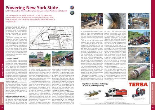
Powering New York State<br />
by Nick H. Strater, Brian C. Dorwart, Brierley Associates, LLC and Lane Puls, Burns and McDonnell<br />
The recent expansion of an electric substation in rural New York State required<br />
trenchless installation of a 345 kilovolt duct bank through an existing rock slope,<br />
below live overhead wires – an optically guided, downhole hammer was selected to<br />
complete the job.<br />
North america<br />
April 2010 - <strong>Trenchless</strong> <strong>International</strong><br />
Representatives of Burns &<br />
McDonnell, Brierly Associates LLC, and<br />
Construction Drilling Inc. collaborated in<br />
the development of a plan to drill large<br />
diameter holes through the rock slope<br />
using the optically guided downhole<br />
hammers.<br />
The existing substation rests within a<br />
topographic “bowl”, and sits near the toe<br />
of a 35 foot high, vertical rock slope. With<br />
the close proximity of live electric facilities<br />
at the crest and toe of the slope, conventional<br />
rock excavation by blasting was not<br />
feasible, and a rock breaker would have<br />
been too expensive due to rock strength<br />
and work area restrictions. Therefore, it<br />
was determined that trenchless installation<br />
of the cables would be required to<br />
minimise impact to the slope and adjacent<br />
substation facilities.<br />
A powerful solution<br />
<strong>Trenchless</strong> design and construction<br />
planning was restricted by the presence of<br />
overhead, high voltage power lines at the<br />
crest and toe of the slope, and the requirement<br />
that the trenchless method could<br />
not use drilling fluid. This constraint was<br />
imposed by the substation owner, due to<br />
concerns about the impacts of inadvertent<br />
drill fluid returns on the adjacent electrical<br />
equipment. Although horizontal directional<br />
drilling (HDD) was initially considered as a<br />
possible means of completing the installation,<br />
it was eventually ruled out due to site<br />
access limitations, the need to use drill<br />
fluid, and relative cost.<br />
Based on these design constraints and<br />
the subsurface conditions, the design<br />
team recommended that the duct bank<br />
installation be completed in holes drilled<br />
with an optically guided downhole<br />
hammer, using methods perfected by<br />
Construction Drilling, Inc. (CDI), of western<br />
Massachusetts.<br />
Developing downhole hammers<br />
CDI has developed a means tracking<br />
downhole hammers during drilling.<br />
The guidance system consists of a target-mounted<br />
drill bit, theodolite, and<br />
monitor, which provides the operator with<br />
continuous, real-time information about<br />
the deviation of the desired drilling profile.<br />
Specially designed drill bits and drilling<br />
techniques permit steering. Prior to this<br />
project, CDI had used this technology to<br />
enable precision rock anchor installations<br />
in and around sensitive structures, including<br />
dams and bridge abutments.<br />
For this installation, the optimum trenchless<br />
layout was to install ducts in three<br />
holes; two at 28 inch diameter (electric<br />
ducts), and one at 18 inch diameter<br />
(grounding and communications ducts).<br />
This layout resulted in cost savings, as<br />
the tooling for holes larger than 28 inch<br />
diameter becomes significantly more<br />
expensive. Each of the holes was approximately<br />
60 feet long, located 10 feet apart<br />
(centre-to-centre), and inclined 30 degrees<br />
downward from horizontal. The holes were<br />
each drilled from the top of the rock slope<br />
downward into the substation.<br />
Ultimately, the staging and performance<br />
of the trenchless work for this project were<br />
governed by the overhead electric cables,<br />
which remained energised throughout<br />
construction. The situation was complicated<br />
by the tendency of these cables<br />
to expand and sag downward during<br />
periods of heavy energy loads. To ensure<br />
worker safety, a phased work plan was<br />
developed dictating maximum equipment<br />
height during construction. To meet the<br />
height restrictions, the surface grade in<br />
the vicinity of the drill entry was lowered<br />
by about 7 feet prior to mobilisation of<br />
the drill rig. This was done using small,<br />
low-profile equipment, including Bobcatmounted<br />
hoe rams and excavators.<br />
Using an (Egtechnology) EGT MD 3000<br />
multi-purpose anchor drill, CDI elected<br />
to use a multiple-pass approach for the<br />
drilling. This involved completing a pilot<br />
hole with an eight inch diameter hammer<br />
bit, followed by an 18 inch, and then a<br />
28 inch hammer. The rods required for<br />
this type of drilling need to be very stiff to<br />
accommodate the shallow alignment, and<br />
to withstand the stress needed to withstand<br />
the impact force imposed by the<br />
hammers. In this case, the rods ranged<br />
from 12 to 18 inches in diameter, and were<br />
equipped with a hexagonal quick-release<br />
joint.<br />
The 18 and 28 inch hammers were<br />
equipped with a leading edge extension,<br />
or “stinger”, designed to follow<br />
the pilot hole. The 28 inch hammer was<br />
designed specifically for this project, and<br />
was forged from a single block of steel.<br />
Like most downhole hammers, the tools<br />
employed by CDI are driven by air, with<br />
a velocity of about 3,000 feet per second.<br />
The air exits the hammer face, where it<br />
then serves to remove the cuttings from<br />
the hole. In an effort to protect the adjacent<br />
electric facilities, all cuttings and<br />
dust generated during drilling were captured<br />
in a stuffing box and diverted to an<br />
adjacent containment device, before the<br />
air was discharged into the atmosphere.<br />
The vibrations generated by this equipment<br />
were minimal, well below the site<br />
threshold of 0.5 inches per second, and<br />
the noise generated the hammers was likened<br />
to that an large excavator-mounted<br />
impact hammer (ie, a hoe ram).<br />
During drilling, the passage of the 8 inch<br />
pilot and 18 inch hammer were completed<br />
without issue; each appearing at the toe of<br />
the slope within 6 inches of the surveyed<br />
High Tech in <strong>Trenchless</strong> Technology<br />
35 years of Swiss Engineering<br />
Underground Piercing (Moles)<br />
from Ø 45-190 mm (1.75“-7.5“)<br />
exit point. It was noted during drilling,<br />
however, that there was a “soft” zone in<br />
the rock, approximately 30 feet from the<br />
drill entry location. The soft zone was<br />
interpreted to represent a zone of highly<br />
weathered rock, parallel the high-angle<br />
foliation observed in the rock mass. To<br />
maintain the line and grade across this<br />
zone, the heavier, 28 inch hammer was<br />
equipped with an 8 foot long, 27 inch<br />
diameter steel “barrel” shroud intended to<br />
help bridge the soft zones in the rock, and<br />
keep the bit from dropping during drilling.<br />
Drilling with the shroud proved effective,<br />
although the decreased annulus diminished<br />
the efficiency of cuttings removal,<br />
which in turn caused occasional jamming<br />
of the tools. Although drilling with the<br />
shroud was somewhat more time consuming,<br />
the 28 inch hammer ultimately exited<br />
the toe of the rock slope with six inches of<br />
the design alignment for each hole, which<br />
was well within the limits required for successful<br />
duct installation.<br />
Following completion of the holes, and<br />
duct bundles were assembled using<br />
mechanically-coupled PVC, that minimised<br />
the need for bundle lay-down room.<br />
Following installation of the duct dandles,<br />
a concrete bulkhead was cast at the bottom<br />
of each hole, and the annulus around<br />
the installed duct was tremie-grouted with<br />
a thermal grout.<br />
HDD Machines for directional bores<br />
up to 400 m (1‘300 ft) and Ø 1’000 mm (40”)<br />
TERRA AG, Hauptstrasse 92, 6260 Reiden, Switzerland<br />
phone: +41-62-749 10 10 fax: +41-62-749 10 11 e-mail: terra.ch@bluewin.ch www.terra-eu.eu<br />
Cable Bursters with pulling forces<br />
up to 40 tons (88‘000 lbs)<br />
North america<br />
April 2010 - <strong>Trenchless</strong> <strong>International</strong><br />
32<br />
33