Boring - Trenchless International
Boring - Trenchless International
Boring - Trenchless International

You also want an ePaper? Increase the reach of your titles
YUMPU automatically turns print PDFs into web optimized ePapers that Google loves.
Chemically restoring<br />
pipeline position<br />
By Masahi Komura, Koichi Araki, Hideki Shimada, Takashi Sasaoka,<br />
Kikuo Matsui and Takahisa Tomii<br />
Current renewal methods for pipelines and culverts are very effective for pipe function decline and accident<br />
prevention, but offer little in the way of rehabilitating meandering and slacks of pipes. Continually expanding<br />
urbanisation means that restoring pipeline position using open cut methods has become less desirable, and as<br />
such has led to the development of new pipeline position restoration technologies, such as the chemical injection<br />
method.<br />
Figure 5. Sludge discharge.<br />
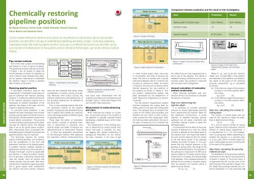
Comparison between prediction and the result of site investigation<br />
Item Prediction Result<br />
Setting depth of injection pipe Gl-6.1 Metres Gl-6.1 Metres<br />
Number of pipe 14 14<br />
Injection amount 8,147 Litres 8,304 Litres<br />
Industry review<br />
April 2010 - <strong>Trenchless</strong> <strong>International</strong><br />
Pipe renewal methods<br />
One of the main causes of meandering<br />
and slacks is a lack of ground support.<br />
The pipelining renewal methods as shown<br />
in Figure 1 are all unable to repair the<br />
shrunk diameter or slacks of a pipeline as<br />
none of these lining methods were effective<br />
for ground improvement underneath<br />
the pipeline. Figure 2 shows a pipeline<br />
after renewal construction.<br />
Restoring pipeline position<br />
A technique commonly used for the<br />
improvement of subsided constructions is<br />
ground upheaval with injection grouting.<br />
However, it is difficult to define the amount<br />
of the injection grouting material that is<br />
necessary for position restoration of the<br />
pipeline, the shape of the pipe, and the<br />
impact to adjacent structures.<br />
To overcome these problems, a new<br />
method has been developed that involves<br />
making a guide space formed primarily in<br />
the direction that the pipeline needs to be<br />
moved before construction. This process<br />
involves building casing pipes and a feeding<br />
pipe for injection grout. The feeding<br />
pipe is set at the guide space location.<br />
After pressurised slurry is sprayed from<br />
the feeding pipe to disturb the ground, the<br />
pipeline position may be improved.<br />
This technique requires the consideration<br />
of drilling diameter, soil conditions,<br />
and the arrangement of the form and<br />
placement intervals of the feeding pipes.<br />
A suitable injection material requires a<br />
gelling time of around ten seconds with no<br />
change in strength, volume or weight after<br />
the injection. In cases of position restoration<br />
by grouting, a grouting material that<br />
uses two liquids, such as cement and<br />
sodium silicate, may be used. After each<br />
component is injected by a grouting pump<br />
into a guide space, both components<br />
are mixed in the same volume. However<br />
Renewal<br />
Method<br />
Indepenent<br />
Pipe<br />
Compound<br />
Pipe<br />
Bilayer<br />
Structure<br />
Reversal<br />
Formation<br />
Production<br />
Reversal<br />
Formation<br />
Guide Pipe<br />
Figure 1. Classification of the renewal<br />
methods.<br />
there are few materials that satisfy these<br />
requirements of cutting, mixing, and gelling.<br />
Moreover when using a pump, the<br />
injection performance and gelling time of<br />
the grouting material are not satisfied at<br />
the same time.<br />
Thus, a new grouting material that suits<br />
the restoration method of the pipeline<br />
position via grouting was developed along<br />
with a method that enables the selection<br />
of the discharge quantity of different types<br />
of grouting material.<br />
These days the extent of restoration<br />
and injection quantity of grouting materials<br />
is determined in advance, and<br />
optimal length and depth of injection are<br />
determined prior to construction. Figures<br />
3 – 6 show the application procedures<br />
for the restoration method. After adopting<br />
the restoration method, snake-advancing<br />
Figure 3. Guide casing pipe setting.<br />
Figure 2. Illustration of pipeline after<br />
renewal construction.<br />
and slack were rehabilitated with the<br />
underpinning effect and increased ground<br />
strength. Figure 7 shows the image of the<br />
soil condition after restoration.<br />
Measurement of snake-advancing<br />
and slack<br />
When restoring the position of a pipeline,<br />
an accurate survey of the location of<br />
the pipeline is typically required before<br />
developing a detailed layout of the restoration<br />
plan.<br />
The measurement of the existing position<br />
is performed by optical survey and,<br />
where man-entry is possible, by manual<br />
logging with results contributing to<br />
background information for the restoration<br />
plan. However, in the case of gas<br />
Figure 4. Chemical injection for preliminary<br />
soil compaction.<br />
Figure 6. Main injection for restoration.<br />
or small conduit pipes when man-entry<br />
is not possible, two kinds of devices are<br />
used. The first is a camera with a survey<br />
instrument attached which is inserted into<br />
the pipe to measure its depth, as shown<br />
in Figure 8. The second is a device which<br />
directly measures the top positions of<br />
the pipeline as shown in Figure 9. This<br />
top position measurement system has<br />
been developed by the Department of<br />
Earth Resources Engineering at Kyushu<br />
University.<br />
The top position measurement system<br />
involves preparing the casing pipe by<br />
drilling down to the pipe with pressurised<br />
slurry. The sprayed slurry is pumped from<br />
a tank on the surface and excavates and<br />
liquefies the soil, which is then continuously<br />
sucked from the casing pipe. After<br />
the hole has been extended to the top of<br />
the pipe a measuring rod is inserted into<br />
Figure 9. Measurement system for position<br />
of pipeline.<br />
Figure 7. Image of the soil condition after<br />
construction.<br />
the drilled hole and the magnetised tip is<br />
set on top of the pipeline. This ability to<br />
establish existing conditions prior to construction<br />
works has resulted in improved<br />
site execution and management.<br />
Amount calculation of restoration<br />
method construction<br />
When planning restoration and construction<br />
works, it is necessary to calculate<br />
the amount of injection.<br />
Step one: determining the<br />
injection depth<br />
It is necessary to consider upheaval<br />
pressure to ensure appropriate planning<br />
when determining the injection depth for<br />
the restoration constructions. A pulse<br />
injection is adopted because ground<br />
upheaval can be easily monitored and<br />
controlled, making it easier to repair the<br />
damaged pipes.<br />
It is assumed that the effect of the pulse<br />
injection is defined as a cone, the centre<br />
of which is defined as the outflow point of<br />
the injection hole. The height and width of<br />
the cone are the distance from the centre<br />
to the real arrival points of the grouting<br />
material, as shown in Figure 11. It is supposed<br />
that the injection pressure of the<br />
grouting is acting within the range of the<br />
cone as mentioned above. For example, if<br />
the upheaval is measured 0.15 MPa at an<br />
injection depth of 10 metres and the radius<br />
of the cone is 10 metres, the vertical angle<br />
is 60 degrees. If the upheaval pressure is<br />
defined as the pressure required project<br />
from the pipeline, the injection depth is<br />
determined as follows.<br />
D= d 1 + d 2 (1)<br />
Figure 8. Image of the water level<br />
measurement, gauge, and recording<br />
paper.<br />
Where D, d 1 , and d 2 are the injection<br />
depth, sum of overburden of the pipeline<br />
and diameter of the pipeline, and distribution<br />
depth of the pulse of the chemical<br />
grouting, respectively, d 2 is calculated<br />
as follows;<br />
(a) If the effective range of the pressure<br />
is acted in 1/3 of the injection effective<br />
radius,<br />
d 2 = d 1 /2 (2)<br />
(b) If the effective range of the pressure<br />
is acted in 1/4 of the injection effective<br />
radius,<br />
d 2 = d 1 /3 (3)<br />
Step two: calculating the number of<br />
casing pipes<br />
The number of casing pipes that are<br />
used for the injection to repair the pipelines<br />
is determined as follows.<br />
N= 2n (4)<br />
N, L, and L3 are the number of casing<br />
pipes, distance of the restoration, and the<br />
interval of casing pipes respectively. n<br />
is calculated as n= L / L3. The arrangement<br />
of casing pipe differs depending on<br />
whether the pipeline is a concrete pipe<br />
or a pvc pipe. When concrete pipes are<br />
used, casing pipes are set up at the joints<br />
of the each of the pipelines.<br />
Step three: calculating the grouting<br />
material per pipe<br />
The distribution of the grouting materials<br />
resulting from the injection site experiment<br />
is shown in Figure 12. From this result, it<br />
is supposed that the circular cone of the<br />
hatching part of the cylinder in Figure 13 is<br />
the range that grouting materials are uniformly<br />
distributed. It is also assumed<br />
Industry review<br />
April 2010 - <strong>Trenchless</strong> <strong>International</strong><br />
58<br />
59