Boring - Trenchless International
Boring - Trenchless International
Boring - Trenchless International

You also want an ePaper? Increase the reach of your titles
YUMPU automatically turns print PDFs into web optimized ePapers that Google loves.
gas<br />
April 2010 - <strong>Trenchless</strong> <strong>International</strong><br />
information was examined that showed<br />
surface gravels to a depth of approximately<br />
12–15 metres. The gravels were<br />
deposited above claystone, shale and<br />
sandstone bedrock, which was expected<br />
to provide a good path for the HDD. This<br />
information had been gathered for a previous<br />
project which was over 100 metres<br />
away from the chosen crossing route.<br />
Additional geotechnical boreholes were<br />
Entec <strong>Trenchless</strong> Engineering is:<br />
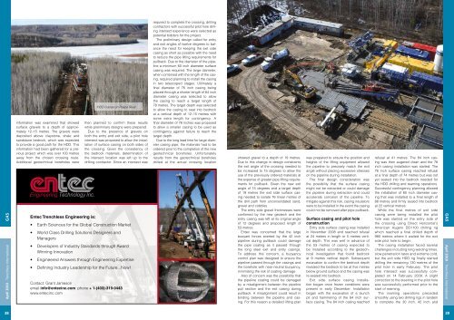
HDD cranes on Peace River.<br />
then planned to confirm these results<br />
while preliminary designs were prepared.<br />
Due to the presence of gravels on<br />
both the entry and exit side, a pilot hole<br />
intersect was proposed to allow the installation<br />
of surface casing on both sides of<br />
the crossing. Given the consistency of<br />
the bedrock materials, determination of<br />
the intersect location was left up to the<br />
drilling contractor. Since an intersect was<br />
• Earth Sciences for the Global Construction Market<br />
• World Class Drilling Solutions Designers and<br />
Managers<br />
• Developers of Industry Standards through Award<br />
Winning Innovation<br />
• Engineered Answers through Engineering Expertise<br />
• Defining Industry Leadership for the Future...Now!<br />
Contact: Grant Jameson<br />
email info@entecinc.com phone + 1-(403)-319-0443<br />
www.entecinc.com<br />
required to complete the crossing, drilling<br />
contractors with successful pilot hole drilling<br />
intersect experience were selected as<br />
potential bidders for the project.<br />
The preliminary design called for entry<br />
and exit angles of twelve degrees to balance<br />
the need for keeping the exit side<br />
casing as short as possible with the need<br />
to reduce the pipe lifting requirements for<br />
pullback. Due to the diameter of the pipeline<br />
a minimum 60 inch diameter surface<br />
casing was required. The large diameter,<br />
when combined with the length of the casing,<br />
required planning to install the casing<br />
in two telescoped stages. Ultimately a<br />
final diameter of 76 inch casing being<br />
placed through a shorter length of 84 inch<br />
diameter casing was selected to allow<br />
the casing to reach a target length of<br />
78 metres. The target depth was selected<br />
to allow the casing to seat into bedrock<br />
at a vertical depth of 12–15 metres with<br />
some extra length for contingency. A<br />
final diameter of 76 inches was proposed<br />
to allow a smaller casing to be used as<br />
contingency against failure to reach the<br />
target depth.<br />
Due to the long lead time for large diameter<br />
casing pipe, the materials had to be<br />
ordered prior to the completion of the new<br />
geotechnical boreholes. Unfortunately<br />
results from the geotechnical boreholes<br />
drilled at the actual crossing location<br />
showed gravel to a depth of 19 metres.<br />
Due to this change in design constraints<br />
the exit angle of the crossing needed to<br />
be increased to 15 degrees to allow the<br />
use of the previously ordered materials at<br />
the expense of greater pipe lifting requirements<br />
for pullback. Given the new exit<br />
angle of 15 degrees and a target depth<br />
of 19 metres the exit side surface casing<br />
needed to isolate 76 linear metres of<br />
the drill path from unconsolidated sand,<br />
gravel and cobbles.<br />
The entry side gravel thicknesses were<br />
confirmed by the new geotech and the<br />
entry casing was left at its original angle<br />
of 12 degrees and proposed length of<br />
53 metres.<br />
Entec was concerned that the large<br />
buoyant forces exerted by the 42 inch<br />
pipeline during pullback could damage<br />
the pipe coating as it passed through<br />
the long steel exit and entry casings.<br />
To address this concern, a buoyancy<br />
control plan was designed to ensure the<br />
pipeline passed through the casings and<br />
the borehole with near neutral buoyancy,<br />
minimising the risk of coating damage.<br />
Also of concern was the possibility that<br />
the pipeline coating could be damaged<br />
by a misalignment between the pipeline<br />
pull section and the exit casing during<br />
pullback. A misalignment could result in<br />
binding between the pipeline and casing.<br />
For this reason a detailed lifting plan<br />
was prepared to ensure the position and<br />
heights of the lifting equipment allowed<br />
the pipeline to precisely match the exit<br />
angle without placing excessive stresses<br />
on the pipeline during installation.<br />
The final design consideration was<br />
the possibility that the surface casing<br />
might not be extracted or could damage<br />
the pipeline during extraction and could<br />
accelerate corrosion of the pipeline. To<br />
mitigate against this risk, casing insulators<br />
were to be installed in the event the casing<br />
could not be removed after pipe pullback.<br />
Surface casing and pilot hole<br />
construction<br />
Entry side surface casing was installed<br />
in November 2008 and reached refusal<br />
at 24 metres in length or 5 metres vertical<br />
depth. This was well in advance of<br />
the 53 metres of casing expected to<br />
be installed according to the geotechnical<br />
investigation that found bedrock<br />
at 9 metres vertical depth. Subsequent<br />
excavation to confirm the bedrock depth<br />
revealed the bedrock to be at five metres<br />
below ground surface and the casing was<br />
re-seated into bedrock.<br />
Exit side surface casing installation<br />
began once frozen conditions were<br />
present in early December. Installation<br />
began with the excavation of a launch<br />
pit and hammering of the 84 inch surface<br />
casing. The 84 inch casing reached<br />
refusal at 41 metres. The 84 inch casing<br />
was then augered clean and the 76<br />
inch casing installation was started. The<br />
76 inch surface casing reached refusal<br />
at a final depth of 74 metres but was not<br />
yet seated into the bedrock needed for<br />
the HDD drilling and reaming operations.<br />
Successful contingency planning allowed<br />
the installation of 60 inch diameter casing<br />
that was installed to a final length of<br />
88 metres and firmly sealed into bedrock<br />
at 22 vertical metres.<br />
While the final metres of exit side<br />
casing were being installed the pilot<br />
hole was started on the entry side of<br />
the crossing using Direct Horizontal’s<br />
American Augers DD1100 drilling rig<br />
which reached a final drilled depth of<br />
980 metres where it waited for the exit<br />
side pilot hole to begin.<br />
The casing installation faced several<br />
challenges including long welding times,<br />
slow penetration rates and extreme cold,<br />
but the exit side HDD rig finally started<br />
drilling the remaining 130 metres of the<br />
pilot hole in early February. The pilot<br />
hole intersect was successfully completed<br />
on 14 February 2009. A slight<br />
correction to the steering in the pilot hole<br />
was successfully performed prior to the<br />
start of reaming.<br />
The reaming operations preceded<br />
smoothly using two drilling rigs in tandem<br />
to complete the 30 inch, 42 inch and<br />
gas<br />
April 2010 - <strong>Trenchless</strong> <strong>International</strong><br />
38<br />
39