Phase Control Using Thyristors - Littelfuse
Phase Control Using Thyristors - Littelfuse
Phase Control Using Thyristors - Littelfuse

You also want an ePaper? Increase the reach of your titles
YUMPU automatically turns print PDFs into web optimized ePapers that Google loves.
AN1003<br />
Application Notes<br />
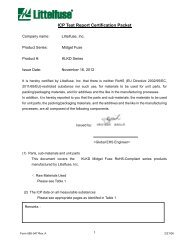
Normalized Sine Wave RMS Voltage Power<br />
as Fraction of Full Conduction<br />
1.8<br />
1.6<br />
1.4<br />
1.2<br />
1.0<br />
0.8<br />
0.6<br />
0.4<br />
0.2<br />
Figure AN1003.3<br />
HALF WAVE<br />
Peak Voltage<br />
Power<br />
RMS<br />
AVG<br />
0<br />
0 20 40 60 80 100 120 140 160 180<br />
θ<br />
Conduction Angle (θ)<br />
Half-Wave <strong>Phase</strong> <strong>Control</strong> (Sinusoidal)<br />
FULL WAVE<br />
θ<br />
θ<br />
phase angle. Thus, a 180° conduction angle in a half-wave circuit<br />
provides 0.5 x full-wave conduction power.<br />
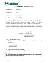
In a full-wave circuit, a conduction angle of 150° provides 97%<br />
full power while a conduction angle of 30° provides only 3% of full<br />
power control. Therefore, it is usually pointless to obtain conduction<br />
angles less than 30° or greater than 150°.<br />
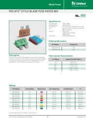
Figure AN1003.5 and Figure AN1003.6 give convenient direct<br />
output voltage readings for 115 V/230 V input voltage. These<br />
curves also apply to current in a resistive circuit.<br />
Output Voltage<br />
Input<br />
Voltage<br />
230 V 115 V<br />
360 180<br />
320 160<br />
280 140<br />
240 120<br />
200 100<br />
160<br />
120<br />
80<br />
40<br />
0<br />
80<br />
60<br />
40<br />
20<br />
HALF WAVE<br />
RMS<br />
θ<br />
Peak Voltage<br />
0 0 20 40 60 80 100 120 140 160 180<br />
Conduction Angle (θ)<br />
AVG<br />
1.8<br />
Figure AN1003.5<br />
Output Voltage of Half-wave <strong>Phase</strong><br />
Normal Sine Wave RMS Voltage Power<br />
as Fraction of Full Conduction<br />
1.6<br />
1.4<br />
1.2<br />
1.0<br />
0.8<br />
0.6<br />
0.4<br />
0.2<br />
Figure AN1003.4<br />
Peak Voltage<br />
Power<br />
RMS<br />
0<br />
0 20 40 60 80 100 120 140 160 180<br />
Conduction Angle (θ)<br />
Symmetrical Full-Wave <strong>Phase</strong> <strong>Control</strong> (Sinusoidal)<br />
Figure AN1003.3 and Figure AN1003.4 also show the relative<br />
power curve for constant impedance loads such as heaters.<br />
Because the relative impedance of incandescent lamps and<br />
motors change with applied voltage, they do not follow this curve<br />
precisely. To use the curves, find the full-wave rated power of the<br />
load, and then multiply by the ratio associated with the specific<br />
AVG<br />
Output Voltage<br />
Input<br />
Voltage<br />
230 V 115 V<br />
360 180<br />
320 160<br />
280 140<br />
240 120<br />
200 100<br />
160<br />
120<br />
80<br />
40<br />
0<br />
Figure AN1003.6<br />
80<br />
60<br />
40<br />
20<br />
FULL WAVE<br />
RMS<br />
θ<br />
Peak Voltage<br />
0<br />
0 20 40 60 80 100 120 140 160 180<br />
Conduction Angle (θ)<br />
AVG<br />
Output Voltage of Full-wave <strong>Phase</strong> <strong>Control</strong><br />
θ<br />
http://www.teccor.com AN1003 - 2 ©2002 Teccor Electronics<br />
+1 972-580-7777 Thyristor Product Catalog