Phase Control Using Thyristors - Littelfuse
Phase Control Using Thyristors - Littelfuse
Phase Control Using Thyristors - Littelfuse

You also want an ePaper? Increase the reach of your titles
YUMPU automatically turns print PDFs into web optimized ePapers that Google loves.
AN1003<br />
Application Notes<br />
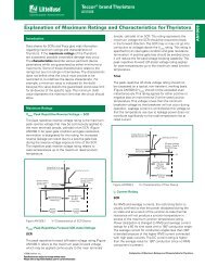
Permanent Magnet Motor <strong>Control</strong><br />
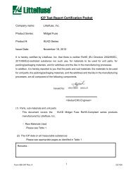
Figure AN1003.16 illustrates a circuit for phase controlling a permanent<br />
magnet (PM) motor. Since PM motors are also generators,<br />
they have characteristics that make them difficult for a<br />
standard triac to commutate properly. <strong>Control</strong> of a PM motor is<br />
easily accomplished by using an alternistor triac with enhanced<br />
commutating characteristics.<br />
AC<br />
Input<br />
Load<br />
SCR1<br />
CR1<br />
R1<br />
R2<br />
2.2 k<br />
+<br />
R3<br />
115 V ac<br />
Input<br />
DC<br />
MTR<br />
Figure AN1003.16 Circuit for <strong>Phase</strong> <strong>Control</strong>ling a Permanent Magnet<br />
Motor<br />
PM motors normally require full-wave DC rectification. Therefore,<br />
the alternistor triac controller should be connected in series with<br />
the AC input side of the rectifier bridge. The possible alternative<br />
of putting an SCR controller in series with the motor on the DC<br />
side of the rectifier bridge can be a challenge when it comes to<br />
timing and delayed turn-on near the end of the half cycle. The<br />
alternistor triac controller shown in Figure AN1003.16 offers a<br />
wide range control so that the alternistror triac can be triggered at<br />
a small conduction angle or low motor speed; the rectifiers and<br />
alternistors should have similar voltage ratings, with all based on<br />
line voltage and actual motor load requirements.<br />
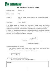
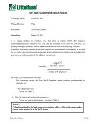
SCR <strong>Phase</strong> <strong>Control</strong><br />
-<br />
1.5 A<br />
250 k<br />
0.1 µF<br />
400 V<br />
Figure AN1003.17 shows a very simple variable resistance halfwave<br />
circuit. It provides phase retard from essentially zero (SCR<br />
full on) to 90 electrical degrees of the anode voltage wave (SCR<br />
half on). Diode CR 1 blocks reverse gate voltage on the negative<br />
half-cycle of anode supply voltage. This protects the reverse gate<br />
junction of sensitive SCRs and keeps power dissipation low for<br />
gate resistors on the negative half cycle. The diode is rated to<br />
block at least the peak value of the AC supply voltage. The retard<br />
angle cannot be extended beyond the 90-degree point because<br />
the trigger circuit supply voltage and the trigger voltage producing<br />
the gate current to fire are in phase. At the peak of the AC<br />
supply voltage, the SCR can still be triggered with the maximum<br />
value of resistance between anode and gate. Since the SCR will<br />
trigger and latch into conduction the first time I GT is reached, its<br />
conduction cannot be delayed beyond 90 electrical degrees with this<br />
circuit.<br />
3.3 k<br />
15 k 1/2 W<br />
0.1 µF<br />
100 V<br />
Q4006LH4<br />
G<br />
HT-32<br />
MT2<br />
MT1<br />
100<br />
0.1 µF<br />
400 V<br />
AC<br />
Input<br />
Voltage<br />
120 V ac<br />
60 Hz<br />
120 V ac<br />
60 Hz<br />
240 V ac<br />
60 Hz<br />
240 V ac<br />
60 Hz<br />
240 V ac<br />
50Hz<br />
Figure AN1003.17<br />
0.8 A<br />
8.5 A<br />
0.8 A<br />
8.5 A<br />
2.5 A<br />
500 k<br />
100 k<br />
1 M<br />
250 k<br />
1 M<br />
IN4003<br />
IN4003<br />
IN4004<br />
IN4004<br />
IN4004<br />
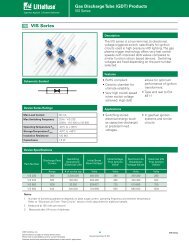
Half-wave <strong>Control</strong>, 0° to 90° Conduction<br />
Figure AN1003.18 shows a half-wave phase control circuit using<br />
an SCR to control a universal motor. This circuit is better than<br />
simple resistance firing circuits because the phase-shifting characteristics<br />
of the RC network permit the firing of the SCR beyond<br />
the peak of the impressed voltage, resulting in small conduction<br />
angles and very slow speed.<br />
AC<br />
Input<br />
Voltage<br />
120 V ac<br />
60 Hz<br />
AC<br />
Load<br />
Current<br />
Universal Motor<br />
M<br />
AC<br />
Supply<br />
R 1<br />
3.3 k<br />
AC<br />
Load<br />
Current<br />
8 A<br />
R 2<br />
CR 1<br />
SCR 1<br />
EC103B<br />
S2010F1<br />
EC103D<br />
S4010F1<br />
T106D1<br />
R3<br />
1 k<br />
Not<br />
Required<br />
1 k<br />
Not<br />
Required<br />
1 k<br />
SCR<br />
D 1<br />
1<br />
CR<br />
R 1<br />
2<br />
HT-32<br />
C 1<br />
R 2 CR 1 SCR 1 C 1<br />
150 k<br />
IN4003<br />
S2015L<br />
0.1µF 200 V<br />
240 V ac<br />
60 Hz<br />
6.5 A<br />
200 k<br />
IN4004<br />
S4008L<br />
0.1µF 400 V<br />
240 V ac<br />
50 Hz<br />
6.5 A<br />
200 k<br />
IN4004<br />
S4008L<br />
0.1µF 400 V<br />
Figure AN1003.18<br />
Half-wave Motor <strong>Control</strong><br />
http://www.teccor.com AN1003 - 6 ©2002 Teccor Electronics<br />
+1 972-580-7777 Thyristor Product Catalog