Analytical Measurement - Nuova Elva
Analytical Measurement - Nuova Elva
Analytical Measurement - Nuova Elva

Create successful ePaper yourself
Turn your PDF publications into a flip-book with our unique Google optimized e-Paper software.
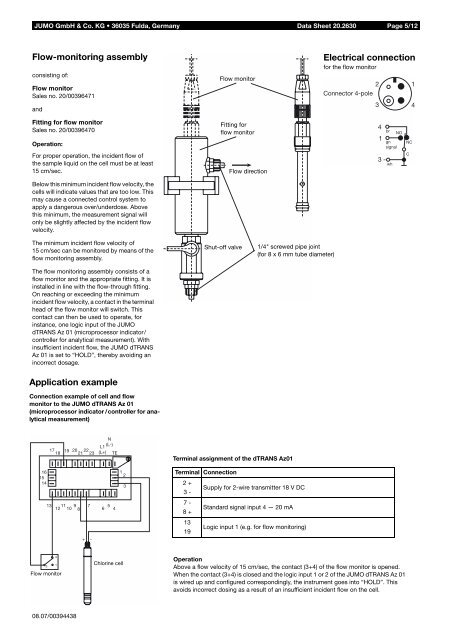
JUMO GmbH & Co. KG • 36035 Fulda, Germany Data Sheet 20.2630 Page 5/12<br />
Flow-monitoring assembly<br />
consisting of:<br />
Flow monitor<br />
Sales no. 20/00396471<br />
and<br />
Flow monitor<br />
Electrical connection<br />
for the flow monitor<br />
2<br />
Connector 4-pole<br />
3<br />
1<br />
4<br />
Fitting for flow monitor<br />
Sales no. 20/00396470<br />
Operation:<br />
For proper operation, the incident flow of<br />
the sample liquid on the cell must be at least<br />
15 cm/sec.<br />
Fitting for<br />
flow monitor<br />
Flow direction<br />
4<br />
1<br />
3 -<br />
br<br />
gn<br />
signal<br />
wh<br />
NO<br />
NC<br />
C<br />
Below this minimum incident flow velocity, the<br />
cells will indicate values that are too low. This<br />
may cause a connected control system to<br />
apply a dangerous over/underdose. Above<br />
this minimum, the measurement signal will<br />
only be slightly affected by the incident flow<br />
velocity.<br />
The minimum incident flow velocity of<br />
15 cm/sec can be monitored by means of the<br />
flow monitoring assembly.<br />
The flow monitoring assembly consists of a<br />
flow monitor and the appropriate fitting. It is<br />
installed in line with the flow-through fitting.<br />
On reaching or exceeding the minimum<br />
incident flow velocity, a contact in the terminal<br />
head of the flow monitor will switch. This<br />
contact can then be used to operate, for<br />
instance, one logic input of the JUMO<br />
dTRANS Az 01 (microprocessor indicator/<br />
controller for analytical measurement). With<br />
insufficient incident flow, the JUMO dTRANS<br />
Az 01 is set to “HOLD”, thereby avoiding an<br />
incorrect dosage.<br />
Shut-off valve<br />
1/4" screwed pipe joint<br />
(for 8 x 6 mm tube diameter)<br />
Application example<br />
Connection example of cell and flow<br />
monitor to the JUMO dTRANS Az 01<br />
(microprocessor indicator /controller for analytical<br />
measurement)<br />
17 19 20 22<br />
18 21 23<br />
L1<br />
(L+)<br />
N<br />
(L-)<br />
TE<br />
Terminal assignment of the dTRANS Az01<br />
16<br />
15<br />
14<br />
1<br />
2<br />
3<br />
Terminal Connection<br />
2 +<br />
Supply for 2-wire transmitter 18 V DC<br />
3 -<br />
13<br />
11 9 7<br />
12 10 8<br />
5<br />
6 4<br />
7 -<br />
8 +<br />
Standard signal input 4 — 20 mA<br />
+ -<br />
13<br />
19<br />
Logic input 1 (e.g. for flow monitoring)<br />
3<br />
4<br />
Flow monitor<br />
1 Chlorine cell<br />
Operation<br />
Above a flow velocity of 15 cm/sec, the contact (3+4) of the flow monitor is opened.<br />
When the contact (3+4) is closed and the logic input 1 or 2 of the JUMO dTRANS Az 01<br />
is wired up and configured correspondingly, the instrument goes into “HOLD”. This<br />
avoids incorrect dosing as a result of an insufficient incident flow on the cell.<br />
08.07/00394438