Analytical Measurement - Nuova Elva
Analytical Measurement - Nuova Elva
Analytical Measurement - Nuova Elva

Create successful ePaper yourself
Turn your PDF publications into a flip-book with our unique Google optimized e-Paper software.
JUMO GmbH & Co. KG • 36035 Fulda, Germany<br />
Data Sheet 20.2545 Page 3/9<br />
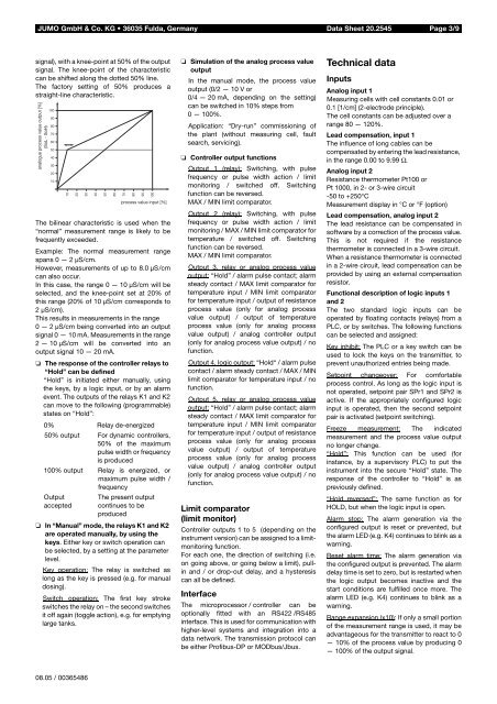
signal), with a knee-point at 50% of the output<br />
signal. The knee-point of the characteristic<br />
can be shifted along the dotted 50% line.<br />
The factory setting of 50% produces a<br />
straight-line characteristic.<br />
The bilinear characteristic is used when the<br />
“normal” measurement range is likely to be<br />
frequently exceeded.<br />
Example: The normal measurement range<br />
spans 0 — 2 µS/cm.<br />
However, measurements of up to 8.0 µS/cm<br />
can also occur.<br />
In this case, the range 0 — 10 µS/cm will be<br />
selected, and the knee-point set at 20% of<br />
this range (20% of 10 µS/cm corresponds to<br />
2µS/cm).<br />
This results in measurements in the range<br />
0 — 2 µS/cm being converted into an output<br />
signal 0 — 10 mA. <strong>Measurement</strong>s in the range<br />
2 — 10 µS/cm will be converted into an<br />
output signal 10 — 20 mA.<br />
❏ The response of the controller relays to<br />
“Hold” can be defined<br />
“Hold” is initiated either manually, using<br />
the keys, by a logic input, or by an alarm<br />
event. The outputs of the relays K1 and K2<br />
can move to the following (programmable)<br />
states on “Hold”:<br />
0% Relay de-energized<br />
50% output For dynamic controllers,<br />
50% of the maximum<br />
pulse width or frequency<br />
is produced<br />
100% output Relay is energized, or<br />
maximum pulse width /<br />
frequency<br />
Output<br />
The present output<br />
accepted continues to be<br />
produced<br />
❏ In “Manual” mode, the relays K1 and K2<br />
are operated manually, by using the<br />
keys. Either key or switch operation can<br />
be selected, by a setting at the parameter<br />
level.<br />
Key operation: The relay is switched as<br />
long as the key is pressed (e.g. for manual<br />
dosing).<br />
Switch operation: The first key stroke<br />
switches the relay on – the second switches<br />
it off again (toggle action), e.g. for emptying<br />
large tanks.<br />
❏ Simulation of the analog process value<br />
output<br />
In the manual mode, the process value<br />
output (0/2 — 10 V or<br />
0/4 — 20 mA, depending on the setting)<br />
can be switched in 10% steps from<br />
0 — 100%.<br />
Application: “Dry-run” commissioning of<br />
the plant (without measuring cell, fault<br />
search, servicing).<br />
❏ Controller output functions<br />
Output 1 (relay): Switching, with pulse<br />
frequency or pulse width action / limit<br />
monitoring / switched off. Switching<br />
function can be reversed.<br />
MAX / MIN limit comparator.<br />
Output 2 (relay): Switching, with pulse<br />
frequency or pulse width action / limit<br />
monitoring / MAX / MIN limit comparator for<br />
temperature / switched off. Switching<br />
function can be reversed.<br />
MAX / MIN limit comparator.<br />
Output 3, relay or analog process value<br />
output: “Hold” / alarm pulse contact; alarm<br />
steady contact / MAX limit comparator for<br />
temperature input / MIN limit comparator<br />
for temperature input / output of resistance<br />
process value (only for analog process<br />
value output) / output of temperature<br />
process value (only for analog process<br />
value output) / analog controller output<br />
(only for analog process value output) / no<br />
function.<br />
Output 4, logic output: “Hold“ / alarm pulse<br />
contact / alarm steady contact / MAX / MIN<br />
limit comparator for temperature input / no<br />
function.<br />
Output 5, relay or analog process value<br />
output: “Hold” / alarm pulse contact; alarm<br />
steady contact / MAX limit comparator for<br />
temperature input / MIN limit comparator<br />
for temperature input / output of resistance<br />
process value (only for analog process<br />
value output) / output of temperature<br />
process value (only for analog process<br />
value output) / analog controller output<br />
(only for analog process value output) / no<br />
function.<br />
Limit comparator<br />
(limit monitor)<br />
Controller outputs 1 to 5 (depending on the<br />
instrument version) can be assigned to a limitmonitoring<br />
function.<br />
For each one, the direction of switching (i.e.<br />
on going above, or going below a limit), pullin<br />
and / or drop-out delay, and a hysteresis<br />
can all be defined.<br />
Interface<br />
The microprocessor / controller can be<br />
optionally fitted with an RS422 /RS485<br />
interface. This is used for communication with<br />
higher-level systems and integration into a<br />
data network. The transmission protocol can<br />
be either Profibus-DP or MODbus/Jbus.<br />
Technical data<br />
Inputs<br />
Analog input 1<br />
Measuring cells with cell constants 0.01 or<br />
0.1 [1/cm] (2-electrode principle).<br />
The cell constants can be adjusted over a<br />
range 80 — 120%.<br />
Lead compensation, input 1<br />
The influence of long cables can be<br />
compensated by entering the lead resistance,<br />
in the range 0.00 to 9.99 Ω.<br />
Analog input 2<br />
Resistance thermometer Pt100 or<br />
Pt 1000, in 2- or 3-wire circuit<br />
-50 to +250°C<br />
<strong>Measurement</strong> display in °C or °F (option)<br />
Lead compensation, analog input 2<br />
The lead resistance can be compensated in<br />
software by a correction of the process value.<br />
This is not required if the resistance<br />
thermometer is connected in a 3-wire circuit.<br />
When a resistance thermometer is connected<br />
in a 2-wire circuit, lead compensation can be<br />
provided by using an external compensation<br />
resistor.<br />
Functional description of logic inputs 1<br />
and 2<br />
The two standard logic inputs can be<br />
operated by floating contacts (relays) from a<br />
PLC, or by switches. The following functions<br />
can be selected and assigned:<br />
Key inhibit: The PLC or a key switch can be<br />
used to lock the keys on the transmitter, to<br />
prevent unauthorized entries being made.<br />
Setpoint changeover: For comfortable<br />
process control. As long as the logic input is<br />
not operated, setpoint pair SPr1 and SPr2 is<br />
active. If the appropriately configured logic<br />
input is operated, then the second setpoint<br />
pair is activated (setpoint switching).<br />
Freeze measurement: The indicated<br />
measurement and the process value output<br />
no longer change.<br />
“Hold”: This function can be used (for<br />
instance, by a supervisory PLC) to put the<br />
instrument into the secure “Hold” state. The<br />
response of the controller to “Hold” is as<br />
previously defined.<br />
“Hold reversed”: The same function as for<br />
HOLD, but when the logic input is open.<br />
Alarm stop: The alarm generation via the<br />
configured output is reset or prevented, but<br />
the alarm LED (e.g. K4) continues to blink as a<br />
warning.<br />
Reset alarm time: The alarm generation via<br />
the configured output is prevented. The alarm<br />
delay time is set to zero, but is restarted when<br />
the logic output becomes inactive and the<br />
start conditions are fulfilled once more. The<br />
alarm LED (e.g. K4) continues to blink as a<br />
warning.<br />
Range expansion (x10): If only a small portion<br />
of the measurement range is used, it may be<br />
advantageous for the transmitter to react to 0<br />
— 10% of the process value by producing 0<br />
— 100% of the output signal.<br />
08.05 / 00365486