Thermocouples - Nuova Elva
Thermocouples - Nuova Elva
Thermocouples - Nuova Elva

Create successful ePaper yourself
Turn your PDF publications into a flip-book with our unique Google optimized e-Paper software.
JUMO GmbH & Co. KG<br />
Delivery address:Mackenrodtstraße 14,<br />
36039 Fulda, Germany<br />
Postal address: 36035 Fulda, Germany<br />
Phone: +49 661 6003-0<br />
Fax: +49 661 6003-607<br />
e-mail: mail@jumo.net<br />
Internet: www.jumo.net<br />
JUMO Instrument Co. Ltd.<br />
JUMO House<br />
Temple Bank, Riverway<br />
Harlow, Essex CM 20 2TT, UK<br />
Phone: +44 1279 635533<br />
Fax: +44 1279 635262<br />
e-mail: sales@jumo.co.uk<br />
Internet: www.jumo.co.uk<br />
JUMO PROCESS CONTROL INC.<br />
885 Fox Chase, Suite 103<br />
Coatesville PA 19320, USA<br />
Phone: 610-380-8002<br />
1-800-554-JUMO<br />
Fax: 610-380-8009<br />
e-mail: info@JumoUSA.com<br />
Internet: www.JumoUSA.com<br />
Data Sheet 90.1000<br />
Page 1/16<br />
Construction and application of thermocouples<br />
The thermoelectric effect<br />
The effect responsible for the action of thermocouples<br />
is the Seebeck effect. If a termperature<br />
difference exists along a wire, this<br />
will cause a displacement of electrical charge.<br />
The amount of the charge displacement<br />
depends on the electrical characteristics of<br />
the chosen material. If two wires of different<br />
materials are joined at one point and then<br />
subjected to a temperature, then a voltage<br />
difference will be generated between the<br />
open ends of the two wires. This voltage depends<br />
on the temperature difference along<br />
the two wires. In order to be able to measure<br />
the temperature at the junction, the temperature<br />
at the open end must be known. If<br />
the temperature of the open end is not<br />
known, then it must be extended (by a compensating<br />
cable) into the zone of known<br />
temperature (reference junction, usually referred<br />
to as the “cold junction”).<br />
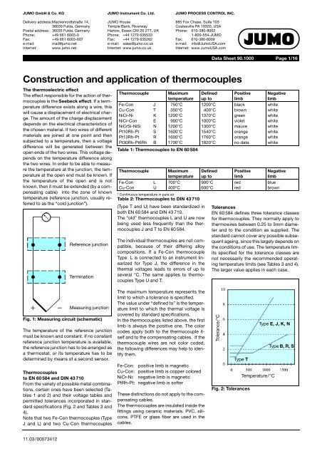
Reference junction<br />
Termination<br />
Thermocouple<br />
Fe-Con<br />
Cu-Con<br />
NiCr-Ni<br />
NiCr-Con<br />
NiCrSi-NiSi<br />
Pt10Rh-Pt<br />
Pt13Rh-Pt<br />
Pt30Rh-Pt6Rh<br />
J<br />
T<br />
K<br />
E<br />
N<br />
S<br />
R<br />
B<br />
Maximum<br />
temperature<br />
750°C<br />
350°C<br />
1200°C<br />
900°C<br />
1200°C<br />
1600°C<br />
1600°C<br />
1700°C<br />
Table 1: <strong>Thermocouples</strong> to EN 60 584<br />
Thermocouple<br />
Fe-Con<br />
Cu-Con<br />
L<br />
U<br />
Maximum<br />
temperature<br />
700°C<br />
400°C<br />
* Continuous temperature in pure air<br />
Table 2: <strong>Thermocouples</strong> to DIN 43 710<br />
(Type T and U) have been standardized in<br />
both EN 60 584 and DIN 43 710.<br />
The “old” thermocouples L and U are now<br />
being used less frequently than the thermocouples<br />
J and T to EN 60 584.<br />
The individual thermocouples are not compatible,<br />
because of their differing alloy<br />
compositions. If a Fe-Con thermocouple<br />
Type L is connected to an instrument linearized<br />
for Type J, the difference in the<br />
thermal voltages leads to errors of up to<br />
several °C. The same applies to thermocouples<br />
Type U and T.<br />
Defined<br />
up to<br />
1200°C<br />
400°C<br />
1370°C<br />
1000°C<br />
1300°C<br />
1540°C<br />
1760°C<br />
1820°C<br />
Defined<br />
up to<br />
900°C<br />
600°C<br />
Positive<br />
limb<br />
black<br />
brown<br />
green<br />
violet<br />
mauve<br />
orange<br />
orange<br />
no data<br />
Positive<br />
limb<br />
red<br />
red<br />
Negative<br />
limb<br />
white<br />
white<br />
white<br />
white<br />
white<br />
white<br />
white<br />
white<br />
Negative<br />
limb<br />
blue<br />
brown<br />
Tolerances<br />
EN 60 584 defines three tolerance classes<br />
for thermocouples. They normally apply to<br />
thermowires between 0.25 to 3mm diameter<br />
and to the condition as supplied. The<br />
standard cannot cover any possible subsequent<br />
ageing, since this largely depends on<br />
the conditions of use. The temperature limits<br />
specified for the tolerance classes are<br />
not necessarily the recommended operating<br />
temperature limits (see Tables 3 and 4).<br />
The larger value applies in each case.<br />
Measuring junction<br />
Fig. 1: Measuring circuit (schematic)<br />
The temperature of the reference junction<br />
must be known and constant. If no constant<br />
reference junction temperature is available,<br />
the reference junction has to be arranged as<br />
a thermostat, or its temperature has to be<br />
determined by means of a second sensor.<br />
<strong>Thermocouples</strong><br />
to EN 60 584 and DIN 43 710<br />
From the variety of possible metal combinations,<br />
certain ones have been selected (Tables<br />
1 and 2) and their voltage tables and<br />
permitted tolerances incorporated in standard<br />
specifications (Fig. 2 and Tables 3 and<br />
4).<br />
Note that two Fe-Con thermocouples (Type<br />
J and L) and two Cu-Con thermocouples<br />
The maximum temperature represents the<br />
limit to which a tolerance is specified.<br />
The value under “defined to” is the temperature<br />
limit to which the thermal voltage is<br />
covered by standard specifications.<br />
In the thermocouples listed above, the first<br />
limb is always the positive one. The color<br />
codes apply both to the thermocouple itself<br />
and to the compensating cables. If the<br />
thermocouple wires are not color coded,<br />
the following differences may help to identify<br />
them.<br />
Fe-Con: positive limb is magnetic<br />
Cu-Con: positive limb is copper colored<br />
NiCr-Ni: negative limb is magnetic<br />
PtRh-Pt: negative limb is softer<br />
These distinctions do not apply to the compensating<br />
cables.<br />
The thermocouples are insulated inside the<br />
fittings using ceramic materials. PVC, silicone,<br />
PTFE or glass fiber are used in the<br />
cables.<br />
Tolerance/°C<br />
Type E, J, K, N<br />
Type B, R, S<br />
Type T<br />
Temperature/°C<br />
Fig. 2: Tolerances<br />
11.03/00073412