Thermocouples - Nuova Elva
Thermocouples - Nuova Elva
Thermocouples - Nuova Elva

You also want an ePaper? Increase the reach of your titles
YUMPU automatically turns print PDFs into web optimized ePapers that Google loves.
JUMO GmbH & Co. KG<br />
Delivery address:Mackenrodtstraße 14,<br />
36039 Fulda, Germany<br />
Postal address: 36035 Fulda, Germany<br />
Phone: +49 661 6003-0<br />
Fax: +49 661 6003-607<br />
e-mail: mail@jumo.net<br />
Internet: www.jumo.net<br />
JUMO Instrument Co. Ltd.<br />
JUMO House<br />
Temple Bank, Riverway<br />
Harlow, Essex CM 20 2TT, UK<br />
Phone: +44 1279 635533<br />
Fax: +44 1279 635262<br />
e-mail: sales@jumo.co.uk<br />
Internet: www.jumo.co.uk<br />
JUMO PROCESS CONTROL INC.<br />
885 Fox Chase, Suite 103<br />
Coatesville PA 19320, USA<br />
Phone: 610-380-8002<br />
1-800-554-JUMO<br />
Fax: 610-380-8009<br />
e-mail: info@JumoUSA.com<br />
Internet: www.JumoUSA.com<br />
Data Sheet 90.1000<br />
Page 5/16<br />
The material KER 610 has a higher alkali<br />
content (60% AI 2 O 3 , 37% SiO 2 , 3% alkali)<br />
and, therefore, a low insulation resistance<br />
of about 10 4 Ω x cm at 1000°C. Because of<br />
the high silicon dioxide content, it cannot<br />
be used in a reducing atmosphere. Compared<br />
with KER 710, it has only one-ninth<br />
the thermal conductivity; its mechanical<br />
stability is good.<br />
The advantage of KER 610 is its price,<br />
which is only about one-fifth that of KER<br />
710.<br />
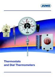
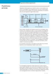
For the terminal heads, DIN 43 729 defines<br />
the two forms A and B, which differ in<br />
size and also slightly in style.<br />
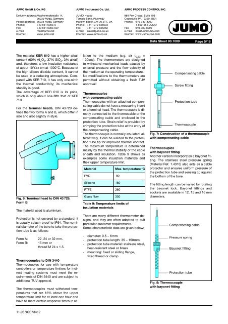
Fig. 6: Terminal head to DIN 43 729,<br />
Form B<br />
The material used is aluminium.<br />
Protection is not covered by a standard; it<br />
is usually splash-proof to IP54. The nominal<br />
diameter of the bore to take the protection<br />
tube is as follows:<br />
Form A:<br />
Form B:<br />
22, 24 or 32 mm.<br />
15 mm or<br />
thread M 24 x 1.5.<br />
<strong>Thermocouples</strong> to DIN 3440<br />
<strong>Thermocouples</strong> for use with temperature<br />
controllers or temperature limiters for indirect<br />
heating systems must meet the requirements<br />
of DIN 3440 and are subject to<br />
additional TUV approval.<br />
The thermocouples must withstand temperatures<br />
that are 15% above the upper<br />
temperature limit for at least one hour and<br />
have to meet certain response times in relation<br />
to the medium (e.g. air t 0.63 =<br />
120sec). The thermometers are designed<br />
to withstand mechanical loads caused by<br />
external pressure and the flow velocity of<br />
the medium at the operating temperature.<br />
No modifications to the thermometers are<br />
permitted without obtaining a fresh TUV<br />
approval!<br />
<strong>Thermocouples</strong><br />
with compensating cable<br />
<strong>Thermocouples</strong> with an attached compensating<br />
cable do not have a measuring insert<br />
or a terminal head. The thermocouple is directly<br />
connected to the thermocable or the<br />
compensating cable and enclosed in the<br />
protection tube. Strain relief is provided by<br />
crimping the protection tube at the entry of<br />
the compensating cable.<br />
The thermocouple is normally insulated; alternatively,<br />
it can be welded to the protection<br />
tube tip for improved thermal contact.<br />
The maximum temperature is determined<br />
mainly by the thermal stability of the cable<br />
sheath and insulation. Table 9 shows as<br />
examples some insulation materials and<br />
their upper temperature limit.<br />
Material Max. temperature °C<br />
PVC 80<br />
Silicone 180<br />
PTFE 260<br />
Glass fiber 350<br />
Table 9: Temperature limits of<br />
insulation materials<br />
There are many different thermometer designs,<br />
and they are often adapted to suit<br />
particular customer requirements.<br />
Some characteristic data are given below:<br />
- diameter: 0.5 – 6mm<br />
- protection tube length: 35 – 150mm<br />
- protection tube material: stainless steel,<br />
heat-resistant steel or brass<br />
- mounting: fixed or sliding flange,<br />
fixed thread or clamp<br />
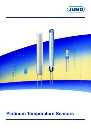
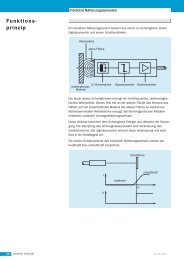
Fig. 7: Construction of a thermocouple<br />
with compensating cable<br />
<strong>Thermocouples</strong><br />
with bayonet fitting<br />
Another version incorporates a bayonet fitting.<br />
The stainless steel pressure spring<br />
(Material Ref. 1.4310) also acts as a cable<br />
protector and ensures uniform pressure of<br />
the protection tube and sensing tip against<br />
the bottom of the bore.<br />
The fitting length can be varied by rotating<br />
the bayonet lock. Bayonet fittings and<br />
sockets are available in 12, 15 and 16 mm<br />
diameters.<br />
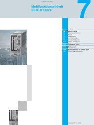
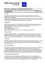
Fig. 8: Thermocouple<br />
with bayonet fitting<br />
Compensating cable<br />
Screw fitting<br />
Protection tube<br />
Thermocouple<br />
Compensating cable<br />
Pressure spring<br />
Bayonet fitting<br />
Protection tube<br />
11.03/00073412