Mechanical Property Characterization of LPCVD Silicon Nitride Thin ...
Mechanical Property Characterization of LPCVD Silicon Nitride Thin ...
Mechanical Property Characterization of LPCVD Silicon Nitride Thin ...

You also want an ePaper? Increase the reach of your titles
YUMPU automatically turns print PDFs into web optimized ePapers that Google loves.
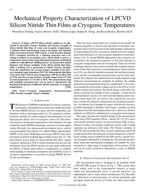
870 JOURNAL OF MICROELECTROMECHANICAL SYSTEMS, VOL. 13, NO. 5, OCTOBER 2004<br />
<strong>Mechanical</strong> <strong>Property</strong> <strong>Characterization</strong> <strong>of</strong> <strong>LPCVD</strong><br />
<strong>Silicon</strong> <strong>Nitride</strong> <strong>Thin</strong> Films at Cryogenic Temperatures<br />
Wen-Hsien Chuang, Student Member, IEEE, Thomas Luger, Rainer K. Fettig, and Reza Ghodssi, Member, IEEE<br />
Abstract—T-shape, <strong>LPCVD</strong> silicon nitride cantilevers are fabricated<br />
to determine Young’s modulus and fracture strength <strong>of</strong><br />
silicon nitride thin films at room and cryogenic temperatures.<br />
A helium-cooled measurement setup is developed and installed<br />
inside a focused-ion-beam (FIB) system. A lead-zirconate-titanate<br />
(PZT) translator powered by a function generator and a dc<br />
voltage is utilized as an actuator, and a silicon diode is used as a<br />
temperature sensor in this setup. Resonant frequencies <strong>of</strong> identical<br />
cantilevers with different “milling masses” are measured to obtain<br />
thickness and Young’s modulus <strong>of</strong> the silicon nitride thin films,<br />
while a bending test is performed to obtain fracture strength.<br />
From the experiment, the average Young’s modulus <strong>of</strong> low-pressure<br />
chemical-vapor deposition (<strong>LPCVD</strong>) silicon nitride thin films<br />
varies from 260.5 GPa at room temperature (298 K) to 266.6 GPa<br />
at 30 K, and the average fracture strength ranges from 6.9 GPa<br />
at room temperature to 7.9 GPa at 30 K. The measurement setup<br />
and technique presented here can be used to characterize the<br />
mechanical properties <strong>of</strong> different MEMS materials at cryogenic<br />
temperatures. [1142]<br />
Index Terms—Cryogenic temperatures, focused-ion-beam<br />
(FIB), fracture strength, Young’s modulus.<br />
I. INTRODUCTION<br />
THE advances <strong>of</strong> MEMS technologies in sensors, actuators,<br />
instruments, and propulsion systems have made it possible<br />
to develop MEMS devices for space and low-temperature applications<br />
such as microspacecrafts [1], [2], miniature communications<br />
satellites [3], meteorological instrumentation [4], and<br />
high-pressure check valves in cryogenic coolers [5]. The reduction<br />
<strong>of</strong> power and thermal requirements with miniature size and<br />
weight has made MEMS technologies attractive for these applications.<br />
Recently, two-dimensional microshutter arrays, used as<br />
a programmable field selector for a Multi-Object Spectrometer<br />
(MOS) on the James Webb Space Telescope (JWST), have been<br />
developed at NASA Goddard Space Flight Center [6], [7]. The<br />
microshutter arrays, made <strong>of</strong> silicon nitride thin films, require<br />
cryogenic operation at 30 K to reduce thermal emission into the<br />
instrument. Since the JWST operates in outer space without the<br />
possibility <strong>of</strong> human intervention or maintenance, a complete<br />
understanding <strong>of</strong> mechanical properties and reliability issues at<br />
cryogenic temperatures is necessary to design MEMS devices<br />
for this environment.<br />
Manuscript received August 14, 2003; revised January 12, 2004. This<br />
work was supported by NASA/Goddard Space Flight Center under Grant<br />
NAG512011. Subject Editor G. K. Fedder<br />
W.-H. Chuang, T. Luger, and R. Ghodssi are with the Department <strong>of</strong> Electrical<br />
and Computer Engineering and the Institute for Systems Research, University<br />
<strong>of</strong> Maryland, College Park, MD 20742 USA (e-mail: ghodssi@eng.umd.edu).<br />
R. K. Fettig works as an independent consultant.<br />
Digital Object Identifier 10.1109/JMEMS.2004.836815<br />
1057-7157/04$20.00 © 2004 IEEE<br />
There has been a long history for scientists to investigate the<br />
material properties <strong>of</strong> macroscale specimen at cryogenic temperatures<br />
[8]. Current research in this field includes applications<br />
<strong>of</strong> superconductivity [9], cryosurgery systems [10], low-temperature<br />
biotechnology [11], and cryogenic operation <strong>of</strong> microelectronics<br />
[12]. To extend MEMS applications into cryogenic environments,<br />
the mechanical properties <strong>of</strong> thin film materials at<br />
cryogenic temperatures must be investigated. There are several<br />
techniques that have been used to measure the mechanical properties<br />
<strong>of</strong> thin-film materials at room temperature. Direct tension<br />
test [13] is an effective method to measure the mechanical properties<br />
and the corresponding measured data can be easily interpreted.<br />
Nevertheless, the requirements for sample alignment and<br />
deflection measurement are stringent. In addition, the sample<br />
preparation and experiment setup are complicated. A test structure<br />
actuated by electrostatic voltage such as in the M-test [14] is<br />
another widely used method. The disadvantage is that only conductive<br />
materials are suitable for this technique. A probe-based<br />
nanoindentation system [15] with load and displacement resolution<br />
better than 0.01 N and 0.1 nm, respectively, has also<br />
been extensively utilized to characterize the mechanical properties.<br />
An indenter tip is brought in contact with the test structure,<br />
possibly damaging it. Hardness and Young’s modulus are then<br />
calculated from the load-displacement curve. However, all these<br />
methods are difficult to implement in a cryogenic environment.<br />
This paper presents the detailed design <strong>of</strong> the measurement<br />
setup with a PZT translator (PI Inc., Model: PL 122.251) and a<br />
microneedle installed inside a focused-ion-beam (FIB) system.<br />
Instead <strong>of</strong> using conventional cantilevers, beams with T-shape<br />
structures are utilized in this study. The Young’s modulus <strong>of</strong><br />
<strong>LPCVD</strong> silicon nitride thin films at room temperature and 30 K<br />
is characterized by measuring the resonant frequencies with different<br />
milling masses (milled by the FIB system), and the fracture<br />
strength is obtained by a bending test. The present measurement<br />
setup and experimental techniques are suitable for measurement<br />
in a large range <strong>of</strong> temperatures (from room to 20 K)<br />
and can be easily extended to characterize a series <strong>of</strong> MEMS<br />
materials.<br />
II. DESIGN OF CRYOGENIC MEASUREMENT SETUP<br />
The measurement setup is designed to be installed inside<br />
a FEI-620 FIB system as shown in Fig. 1. FIB systems have<br />
been widely used in the semiconductor industry to repair<br />
masks and interconnection wires, to provide mask-less ion<br />
implantation, and to study failure mechanisms [16]. Recently,<br />
the fabrication <strong>of</strong> microstructures <strong>of</strong> various geometries and<br />
prototype nanoscale devices [17] have also been successfully
CHUANG et al.: MECHANICAL PROPERTY CHARACTERIZATION OF <strong>LPCVD</strong> SILICON NITRIDE THIN FILMS 871<br />
Fig. 1. FIB system with a measurement setup installed inside.<br />
demonstrated using FIB systems. The FEI 620 used in our experiment<br />
is a dual beam system, with ion and electron columns,<br />
permitting ion milling and in situ scanning electron microscopy<br />
(SEM). This system also has the ability <strong>of</strong> depositing platinum<br />
(Pt) by ion-induced metal-organic chemical-vapor deposition<br />
(MOCVD). These unique capabilities make FIB an appropriate<br />
tool for characterizing the mechanical properties <strong>of</strong> MEMS<br />
materials at cryogenic temperatures.<br />
Fig. 2 shows the configuration <strong>of</strong> the measurement setup<br />
inside the FIB system. Liquid helium (LHe) in combination<br />
with a resistive thermal source is used to control the temperature<br />
from 30 K to room temperature by adjusting the flow<br />
rate <strong>of</strong> LHe and the electrical current flowing through the<br />
resistor. Since the measurement setup operates at temperature<br />
levels much below ambient temperature, heat transfer is the<br />
main concern when designing such a setup [18]. To obtain a<br />
cryogenic environment, a thermally isolated device stage with<br />
cooling power is required. In our design, the cooling power is<br />
provided by a helium diffuser that is connected to a thermally<br />
isolated x-y-z stage (rotate-able and tilt-able) with a flexible<br />
wire providing a thermal path. Since copper has high thermal<br />
conductivity and can be machined easily, the device stage,<br />
helium diffuser and thermal path are made from copper. Three<br />
G-10 (a continuous filament glass cloth material with an epoxy<br />
resin binder) stand<strong>of</strong>fs are used as thermal insulators (thermal<br />
conductivity <strong>of</strong> 0.04 W/m K at 30 K) to minimize conduction<br />
heat transfer between the device stage and the FIB chamber.<br />
Due to a high vacuum ( mbar) inside the FIB system,<br />
convection heat transfer can be neglected. However, in most<br />
cryogenic setups, the primary mode <strong>of</strong> heat transfer is generally<br />
radiant heat transfer. In our design <strong>of</strong> the radiant shield, an aluminized<br />
Mylar layer [19] enclosing the device stage is utilized<br />
to reduce radiant heat transfer (see Fig. 3) since the emissivity<br />
<strong>of</strong> aluminized Mylar is lower than that <strong>of</strong> stainless steel/aluminum<br />
oxide chamber wall. There is no thermal conduction<br />
path between the Mylar shield and the device stage.<br />
A diode temperature sensor attached to the device stage with<br />
thermal response time <strong>of</strong> 10 ms at 4.2 K and accuracy <strong>of</strong> 0.25 K<br />
Fig. 2. Configuration <strong>of</strong> the measurement setup: (a) schematic view and<br />
(b) photograph <strong>of</strong> the system.<br />
Fig. 3. Measurement setup with three layers <strong>of</strong> aluminized Mylar shields.<br />
at 30 K [20] is utilized to measure the temperature <strong>of</strong> the chip.<br />
The temperature reading and calibration is obtained from a temperature<br />
controller [21]. This cryogenic setup has been successfully<br />
tested to achieve temperature as low as 20 K with<br />
a required cooling time <strong>of</strong> 16 min. For actuating test devices,<br />
a PZT translator powered by a function generator and a DC<br />
voltage is attached to a G-10 plate with a stycast epoxy [19].<br />
The G-10 plate is then fixed on a 3-D stage controlled by rotary
872 JOURNAL OF MICROELECTROMECHANICAL SYSTEMS, VOL. 13, NO. 5, OCTOBER 2004<br />
Fig. 4. Schematic diagram <strong>of</strong> a T-shape cantilever for resonant tests.<br />
feed-throughs. A small G-10 tube (10 mm in length, 3.5 mm in<br />
diameter, and 0.6 mm in wall thickness) is attached on the top<br />
surface <strong>of</strong> the PZT translator. A microneedle is mounted to the<br />
metal part at the end <strong>of</strong> this tube. A flexible copper wire (thermal<br />
path) cooling the microneedle is soldered to the metal part <strong>of</strong> the<br />
G-10 tube. This configuration prevents malfunction <strong>of</strong> the PZT<br />
translator as it remains warm during cryogenic operation <strong>of</strong> the<br />
microneedle.<br />
III. DEVICE DESIGN AND EXPERIMENTAL TECHNIQUE<br />
A. Young’s Modulus <strong>of</strong> <strong>Thin</strong> Films<br />
As mentioned earlier, the resonant technique is used to determine<br />
the Young’s modulus <strong>of</strong> silicon nitride thin films. Unlike<br />
conventional cantilevers, a mass is added to the end <strong>of</strong> a<br />
cantilever as shown in Fig. 4 to form a “spring-mass” system<br />
whose first resonant frequency can be measured and computed<br />
analytically. The purpose <strong>of</strong> this design is to reduce the resonant<br />
frequency <strong>of</strong> this T-shape cantilever to a range that can be easily<br />
measured. From beam theory, the first resonant frequency <strong>of</strong> a<br />
T-shape cantilever is expressed as [22], [23]<br />
where is a constant and equal to 0.2357) is the effective<br />
mass <strong>of</strong> the cantilever beam in region A, is the added mass <strong>of</strong><br />
region B, is the first resonant frequency in Hz,<br />
is the effective cantilever length, and is the Young’s modulus.<br />
The area moment <strong>of</strong> inertia is equal to , where<br />
is the width <strong>of</strong> region A, and is the thickness <strong>of</strong> the cantilever.<br />
Here, T-shape cantilevers are modeled as structures under uniaxial<br />
stress. This may violate the condition <strong>of</strong> biaxial stress at<br />
the supporting boundary and lead to error in the expression <strong>of</strong><br />
the resonant frequency. However, this effect can be neglected<br />
due to small introduced error (less than 1.1%) according to finite<br />
element analysis simulations.<br />
In our resonant tests, one cantilever is first pushed vertically<br />
with the microneedle and then released. The approximate reso-<br />
(1)<br />
nant frequency is measured by pointing the electron beam in a<br />
fixed position where the vibrating cantilever moves in and out<br />
<strong>of</strong> the electron beam path. This modulates the secondary electron<br />
detector signal with the frequency <strong>of</strong> vibration. This signal<br />
is acquired with an oscilloscope and the approximate resonant<br />
frequency is determined. Subsequently, the microneedle driven<br />
by the PZT translator contacts with the chip and vibrates the<br />
cantilever near the frequency determined previously. The frequency<br />
is varied over a small range and the response is monitored<br />
to determine the exact resonant frequency and the quality<br />
factor. Fig. 5. shows the schematic mechanism <strong>of</strong> the resonant<br />
test and Fig. 6. is a SEM picture illustrating that each cantilever<br />
vibrates only when the driving frequency <strong>of</strong> the PZT translator<br />
matches with its resonant frequency.<br />
Once the first resonant frequency is determined, the Young’s<br />
modulus from (1) is given by<br />
which is expanded in terms <strong>of</strong> thickness as follows:<br />
where is the mass density. From (3), the dimensions <strong>of</strong> T-shape<br />
cantilevers are critical parameters to calculate Young’s modulus.<br />
In general, the width and length <strong>of</strong> a cantilever are determined<br />
by layout design <strong>of</strong> the optical mask and can be measured<br />
directly inside the FIB system. On the other hand, the uncertainty<br />
<strong>of</strong> the thin film thickness is the primary source <strong>of</strong> error<br />
for the existing method. To solve this problem, the added mass<br />
method has been used to obtain the thickness <strong>of</strong> a cantilever<br />
[24], [25]. A small mass is added to a cantilever and the change<br />
in the resonant frequency due to an added mass is measured to<br />
calculate the thickness and Young’s modulus. The disadvantage<br />
<strong>of</strong> this method is the difficulty to obtain the accurate mass added<br />
to the cantilever. Furthermore, to manipulate a bead (mass) on<br />
the microscale or nanoscale cantilever is a challenging task.<br />
In contrast, the milling mass approach is introduced in our experiment.<br />
The area <strong>of</strong> the milling mass is determined precisely<br />
from the ion-milling pattern. The approximate thickness is estimated<br />
from the milling rate and the milling time, measured by<br />
the milling <strong>of</strong> test samples and End Point Detection (EDP) in<br />
the FIB system, respectively. If a mass is milled away from<br />
the end <strong>of</strong> a cantilever, the first resonant frequency can be expressed<br />
as<br />
The resonant frequencies with different milling mass are<br />
measured and the relation between and is plotted.<br />
Here, the change <strong>of</strong> the effective cantilever length is calculated<br />
by the shift <strong>of</strong> the center <strong>of</strong> the mass in region B due to the<br />
milling mass . Consequently, the y-intercept yields the effective<br />
mass and thickness <strong>of</strong> this T-shape cantilever,<br />
and the slope gives the Young’s modulus.<br />
(2)<br />
(3)<br />
(4)
CHUANG et al.: MECHANICAL PROPERTY CHARACTERIZATION OF <strong>LPCVD</strong> SILICON NITRIDE THIN FILMS 873<br />
Fig. 5. Schematic diagram <strong>of</strong> the mechanism for resonant tests.<br />
Fig. 6. SEM picture <strong>of</strong> a vibrating cantilever. Only the second one from top on<br />
the right column vibrates because the driving frequency <strong>of</strong> the PZT translator is<br />
near its first resonant mode.<br />
B. Fracture Strengths <strong>of</strong> <strong>Thin</strong> Films<br />
For measuring the fracture strength <strong>of</strong> silicon nitride thin<br />
films, bending tests <strong>of</strong> T-shape cantilevers are performed. The<br />
dimensions <strong>of</strong> the T-shape cantilevers used for bending tests<br />
(Fig. 7) are different from those used in the resonant tests. We<br />
select the width and length in region B to be larger than those<br />
in region A such that region B is rigid relative to region A<br />
during the bending test. If a force F is applied to a cantilever at<br />
a distance from the fixed end, the inclination <strong>of</strong> the end<br />
region A (at ) can be expressed as [22], [23]<br />
where is the length <strong>of</strong> region A, is the Young’s modulus,<br />
and is the moment <strong>of</strong> inertial <strong>of</strong> region A. Equation (5) is valid<br />
only when is small. If we assume is equal to<br />
, the above equation can be rewritten as<br />
Therefore, the maximum moment M about the fixed end <strong>of</strong> the<br />
beam is<br />
(5)<br />
(6)<br />
(7)<br />
Fig. 7. Schematic diagram <strong>of</strong> a cantilever for bending tests.<br />
In our experiment, the large blade <strong>of</strong> a cantilever (region B) is<br />
pushed by the micro-needle through a rotation angle . The peak<br />
stress occurred at the fixed end and is expressed as<br />
where is the half thickness <strong>of</strong> the cantilever. Since the accurate<br />
position and force <strong>of</strong> the micro-needle applied to the cantilever<br />
are difficult to measure, the stress determined from (8)<br />
has the advantage <strong>of</strong> being insensitive to the force position if<br />
n is large, and the value <strong>of</strong> the applied force is not needed. The<br />
maximum bending angle before failure is measured and the fracture<br />
strength <strong>of</strong> the silicon nitride thin film can be obtained.<br />
IV. DEVICE PREPARATION<br />
T-shape cantilevers are fabricated using bulk micro-machining<br />
techniques. A layer <strong>of</strong> low-stress <strong>LPCVD</strong> silicon<br />
nitride with an approximate thickness <strong>of</strong> 0.45 m and residual<br />
stress <strong>of</strong> 200 MPa is first deposited on a 500- m-thick silicon<br />
substrate. The silicon nitride thin film is then patterned by<br />
reactive ion etching (RIE). Finally, the wafer is placed into a<br />
20%, 72 C potassium hydroxide (KOH) solution [26] for 2.5<br />
hours with uniform agitation to release the T-shape cantilever<br />
structures. The etching apparatus sits inside a constant-temperature<br />
thermal bath (NESLAB GP-300) with a condenser to keep<br />
(8)
874 JOURNAL OF MICROELECTROMECHANICAL SYSTEMS, VOL. 13, NO. 5, OCTOBER 2004<br />
Fig. 8. SEM picture <strong>of</strong> cantilever 1 at the first resonant mode.<br />
the concentration <strong>of</strong> KOH steady. A magnet positioned under<br />
the solution beaker along with a magnetic stirring bar in the<br />
KOH solution is used to produce uniform agitation (1000 rpm).<br />
The etch rate from the experiment is 0.79 m/min. The depth<br />
<strong>of</strong> the etched v-groove is 118.5 m and the undercut <strong>of</strong> silicon<br />
(lateral etch) is 4 m.<br />
V. MEASUREMENT RESULTS<br />
A. Young’s Modulus<br />
Before the resonant test, ion milling is performed to obtain<br />
a fixed boundary <strong>of</strong> the cantilevers, while the dimensions are<br />
measured directly inside the FIB system. A T-shape cantilever<br />
(cantilever 1) driven to its first resonant mode by the PZT translator<br />
is shown in Fig. 8. The vibration amplitude <strong>of</strong> this cantilever<br />
near the resonant frequency is measured and the resulting<br />
resonant spectrum is shown in Fig. 9. The quality factor determined<br />
from the resonant spectrum is as high as 2050, which is<br />
expected due to the high vacuum inside the FIB system. Therefore,<br />
the damping effect for Young’s modulus extraction can be<br />
neglected (the error is less than %). Different masses<br />
at the end <strong>of</strong> the cantilever are milled away by the ion-milling<br />
function <strong>of</strong> the FIB system as shown in Fig. 10 and the corresponding<br />
resonant frequencies are measured as shown in Table I.<br />
Here, a density <strong>of</strong> kg/m for <strong>LPCVD</strong> silicon nitride<br />
thin films [27] is used to calculate the milling mass . The relation<br />
between and is plotted and the equation <strong>of</strong> a<br />
straight line for best fitting is found using Mathematica (version<br />
4.2, s<strong>of</strong>tware package developed by Wolfram Research Inc.) as<br />
shown in Fig. 11. Hence, the extracted thickness and Young’s<br />
modulus are obtained from the y-intercept and the slope <strong>of</strong> this<br />
straight line, respectively. In our experiments, only one cantilever<br />
is milled away several times. For the other cantilevers,<br />
a single mass is milled away for the extraction <strong>of</strong> the thickness<br />
and Young’s modulus. Table II presents the values <strong>of</strong> the extracted<br />
thickness <strong>of</strong> the cantilever and the Young’s modulus <strong>of</strong><br />
our <strong>LPCVD</strong> silicon nitride thin films.<br />
From Table II, the average Young’s modulus <strong>of</strong> low-stress,<br />
<strong>LPCVD</strong> silicon nitride thin films at room temperature is<br />
260.5 GPa with a standard deviation <strong>of</strong> 5.4 GPa. The Young’s<br />
modulus <strong>of</strong> bulk silicon nitride is known to be in the range <strong>of</strong><br />
207 to 310 GPa [28]. Schneider and Tucker reported a Young’s<br />
modulus <strong>of</strong> 230–265 GPa for 0.2–0.3 m silicon nitride thin<br />
films [29], and Tabata et al. obtained 290 GPa for 0.5 m<br />
<strong>LPCVD</strong> silicon nitride thin films [30]. Therefore, the measured<br />
Young’s modulus is certainly within the range <strong>of</strong> the reported<br />
values.<br />
After room temperature tests are finished, all cantilevers are<br />
cooled down to 30 K in the cryogenic setup and the resonant frequencies<br />
<strong>of</strong> these cantilevers are measured again. The Young’s<br />
modulus calculated from (4) is shown in Table III and has an<br />
average <strong>of</strong> 266.6 GPa with a standard deviation <strong>of</strong> 4.1 GPa.<br />
Here, the value <strong>of</strong> (K ) is used as the coefficient <strong>of</strong><br />
thermal expansion (CTE) <strong>of</strong> silicon nitride for dimension modification.<br />
Although the value <strong>of</strong> CTE <strong>of</strong> silicon nitride varies<br />
from to (K ) [27], [31] and is also<br />
a function <strong>of</strong> temperature, less than 0.1% error is introduced in<br />
the calculation <strong>of</strong> the Young’s modulus if only a single value<br />
is used. However, the variation <strong>of</strong> temperature will introduce<br />
thermo-mechanical stress and may cause local spring hardening<br />
or s<strong>of</strong>tening at the supporting boundary. The thermo-mechanical<br />
stress can be expressed as [27]<br />
(9)<br />
(10)<br />
where is the thermal strain <strong>of</strong> silicon nitride, is the CTE,<br />
is the thermo-mechanical stress <strong>of</strong> silicon nitride, and is<br />
Poisson’s ratio. If the value <strong>of</strong> (K ) is used for<br />
the CTE <strong>of</strong> silicon, this thermomechanical stress is found to be<br />
MPa at 30 K. Since the combination <strong>of</strong> this thermomechanical<br />
stress and the residual stress is still in a range <strong>of</strong> few<br />
hundred MPa, this effect can be ignored with negligible error.<br />
From our measurements, the Young’s modulus increases<br />
from 260.5 GPa at 298 K to 266.6 GPa at 30 K. The increase<br />
<strong>of</strong> the Young’s modulus at low temperature is significant<br />
according to the Student T test [32] and can be<br />
explained by the fact that the distance <strong>of</strong> atom or ion separation<br />
decreases at low temperature. This distance is determined by<br />
the minimum potential energy, i.e., the first derivative <strong>of</strong> the<br />
potential energy is equal to zero. As temperature is decreased,<br />
interatomic force (second derivative <strong>of</strong> the potential energy)<br />
tends to increase because <strong>of</strong> the decrease <strong>of</strong> atomic distance.<br />
Since elastic reaction is due to the action <strong>of</strong> this force, the<br />
Young’s modulus increases at lower temperatures.<br />
B. Fracture Strength<br />
A bending T-shape cantilever before and after fracture is<br />
shown in Fig. 12. In our experiments, T-shape cantilevers with<br />
larger region B are fabricated to make region B relatively rigid<br />
to region A and to minimize the measurement error <strong>of</strong> .<br />
Although the deflection at the tip <strong>of</strong> a cantilever caused by<br />
the stress gradient is proportional to the square <strong>of</strong> the beam<br />
length, no obvious bending curvature is found even in our<br />
longest cantilever. The dimensions <strong>of</strong> conventional cantilevers<br />
used in bending tests can vary in a large range from mm to<br />
nm [33]–[35], mainly determined by the considerations <strong>of</strong><br />
measurement setups and stress gradients <strong>of</strong> the beams.
CHUANG et al.: MECHANICAL PROPERTY CHARACTERIZATION OF <strong>LPCVD</strong> SILICON NITRIDE THIN FILMS 875<br />
Fig. 9. Resonant spectrum <strong>of</strong> cantilever 1. The insert is the close-up <strong>of</strong> the spectrum near the resonant frequency.<br />
Fig. 10. SEM picture <strong>of</strong> cantilever 1 with 12.15 pg milling mass.<br />
Several phenomena are observed in our bending tests. First,<br />
we find the cantilevers with larger than 3 m still survive<br />
the bending force even when they reach the side walls <strong>of</strong> the<br />
v-grooves as shown in Fig. 13. Second, since the displacement<br />
<strong>of</strong> the cantilever is much larger than its thickness at the fracture<br />
point, in-plane stress cannot be neglected. Hence, (8) is not<br />
valid in this condition. Third, as mentioned in the section <strong>of</strong> device<br />
preparation, the boundary at the end <strong>of</strong> the cantilever is<br />
floating due to the undercut <strong>of</strong> silicon in the KOH solution. To<br />
accommodate these factors, an ANSYS finite element analysis<br />
(FEA) model is developed to obtain accurate fracture strength.<br />
Due to the symmetry <strong>of</strong> a T-shape cantilever, only half <strong>of</strong> the<br />
test specimen is needed in this model. In addition, the curvature<br />
<strong>of</strong> region A caused by the fabrication process is measured and<br />
used to simulate the stress concentration <strong>of</strong> region A.<br />
Instead <strong>of</strong> measuring fracture angle at , the displacement<br />
at is determined and used as the input <strong>of</strong> the<br />
FEA model as shown in Fig. 14. From the simulation results,<br />
the maximum stress occurs at the edge <strong>of</strong> region A. Here, the<br />
Young’s moduli <strong>of</strong> 260.5 GPa and 266.6 GPa are used for 298<br />
K and 30 K respectively and the Poisson’s ratio <strong>of</strong> 0.23 is used<br />
for both temperatures in this model [36]. The fracture strengths<br />
<strong>of</strong> <strong>LPCVD</strong> silicon nitride at 298 K and 30 K are presented in<br />
Table IV. From this table, the average fracture strength at 298<br />
K is 6.9 GPa with a standard deviation <strong>of</strong> 0.6 GPa. In previous<br />
work, Yang et al. reported the fracture strength <strong>of</strong> 12.1 GPa [37]<br />
and Coles et al. obtained 6.4 GPa [38], both for <strong>LPCVD</strong> silicon<br />
nitride thin films. The difference is mainly caused by different<br />
fabrication processes and testing techniques. Hence, the measured<br />
fracture strength is still within the range compared with<br />
the reported values.<br />
The average fracture strength at 30 K is 7.9 GPa with a standard<br />
deviation <strong>of</strong> 0.7 GPa. The increase <strong>of</strong> the fracture strength<br />
at low temperature can be explained by less thermal agitation.<br />
As the temperature is lowered, the atoms in the specimen vibrate<br />
less vigorously. A larger applied stress is required to initiate<br />
a crack to break the specimen, leading to a higher fracture<br />
strength. However, the above explanation is only valid for<br />
a defect-free material. For most brittle materials, the fracture<br />
strength is determined by stress concentrations from growth
876 JOURNAL OF MICROELECTROMECHANICAL SYSTEMS, VOL. 13, NO. 5, OCTOBER 2004<br />
Fig. 11. Linear plot <strong>of</strong> milling mass � versus @v � A for cantilever 1.<br />
TABLE I<br />
DIMENSIONS OF CANTILEVER 1WITH EFFECTIVE LENGTH AND MEASURED<br />
RESONANT FREQUENCY<br />
TABLE II<br />
DIMENSIONS OF CANTILEVERS WITH EXTRACTED THICKNESS AND<br />
YOUNG’S MODULUS<br />
flaws, yet their variations at cryogenic temperatures are still not<br />
clear.<br />
TABLE III<br />
RESONANT FREQUENCY AND EXTRACTED YOUNG’S MODULUS<br />
AT 298 K AND 30 K<br />
C. Discussion<br />
From this study, the Young’s modulus <strong>of</strong> <strong>LPCVD</strong> silicon nitride<br />
thin films increases by 2.3% from 298 K to 30 K, while<br />
the fracture strength increases by 14.5%. Several uncertainties<br />
may cause errors in the extraction <strong>of</strong> these properties. First, even<br />
though the errors introduced from using a single value <strong>of</strong> CTE<br />
and Poisson’s ratio is small, exact values at cryogenic temperatures<br />
should be obtained to minimize these errors. Second, the<br />
cross sections <strong>of</strong> the test specimens are not perfectly rectangular<br />
due to the fabrication process, especially at the smaller widths.<br />
This effect is not considered in the FEA model. Third, the temperature<br />
<strong>of</strong> the test cantilever may be different from the temperature<br />
measurement <strong>of</strong> the diode sensor due to thermal resistance<br />
between the device chip and copper (device) stage. Furthermore,<br />
radiant heat transfer is not zero since the device stage<br />
is not wholly enclosed by aluminized Mylar layers. However,<br />
the influence <strong>of</strong> temperature uncertainty is insignificant because<br />
<strong>of</strong> small temperature dependence <strong>of</strong> the Young’s modulus and<br />
fracture strength <strong>of</strong> <strong>LPCVD</strong> silicon nitride thin films. An inte-
CHUANG et al.: MECHANICAL PROPERTY CHARACTERIZATION OF <strong>LPCVD</strong> SILICON NITRIDE THIN FILMS 877<br />
Fig. 12. SEM pictures <strong>of</strong> a cantilever (a) before and (b) after fracture during<br />
the bending test.<br />
Fig. 13. Bending test <strong>of</strong> a cantilever with v aQ"m.<br />
grated temperature sensor is developed to measure the chip temperature<br />
more accurately for further study.<br />
For designing MEMS devices operating at cryogenic temperatures<br />
using <strong>LPCVD</strong> silicon nitride thin films, one can use the<br />
values <strong>of</strong> the Young’s modulus and fracture strength at room<br />
temperature as the first design parameters. This method is conservative<br />
and safe for the first device demonstration. However,<br />
for composite structures, the stress caused by the mismatch <strong>of</strong><br />
CTE at cryogenic temperatures is more pronounced than the<br />
change <strong>of</strong> the Young’s modulus and fracture strength, especially<br />
for optical MEMS devices requiring flat surfaces. Fig. 15 shows<br />
a SEM picture <strong>of</strong> a microshutter test device at 298 K and 30 K.<br />
Fig. 14. ANSYS finite element analysis model (a) mesh <strong>of</strong> the test specimen<br />
using “solid 92” element (b) the stress distribution.<br />
The blade <strong>of</strong> this microshutter is made <strong>of</strong> silicon nitride, aluminum,<br />
and cobalt/iron thin films where it curls up 15 mat<br />
30 K due to this effect.<br />
VI. CONCLUSION<br />
This paper presents the design and development <strong>of</strong> a<br />
measurement setup with liquid helium input for mechanical<br />
property characterization <strong>of</strong> thin film materials at cryogenic<br />
temperatures. This setup has been successfully tested to achieve<br />
temperature down to 20 K. The concept <strong>of</strong> using T-shape cantilevers<br />
instead <strong>of</strong> conventional ones is discussed and the test<br />
specimens are fabricated by bulk micromaching technique,<br />
which is a relatively simple process. The resonant test is carried<br />
out to obtain the Young’s modulus <strong>of</strong> <strong>LPCVD</strong> silicon nitride<br />
thin films. To determine the thickness <strong>of</strong> the cantilever, the<br />
variation <strong>of</strong> resonant frequencies with different milling masses<br />
is recorded and an analytic model is developed to extract the<br />
thickness and Young’s modulus simultaneously. The fracture<br />
behavior <strong>of</strong> <strong>LPCVD</strong> silicon nitride is characterized using the<br />
bending test combined with a FEA model.<br />
From the experiment, the Young’s modulus <strong>of</strong> <strong>LPCVD</strong><br />
silicon nitride thin films varies from 260.5 GPa at 298 K to<br />
266.6 GPa at 30 K, and the fracture strength ranges from<br />
6.9 GPa at 298 K to 7.9 GPa at 30 K. The increase <strong>of</strong> the
878 JOURNAL OF MICROELECTROMECHANICAL SYSTEMS, VOL. 13, NO. 5, OCTOBER 2004<br />
TABLE IV<br />
TEST RESULTS OBTAINED USING ANSYS FEA MODEL WITH BENDING MEASUREMENTS AS INPUTS AT 298 K AND 30 K<br />
Fig. 15. SEM pictures <strong>of</strong> a microshutter device at (a) 298 K and (b) 30 K (The<br />
device is fabricated at NASA Goddard Space Flight Center).<br />
Young’s modulus and fracture strength is attributed to the<br />
decrease in thermal agitation between atoms at cryogenic<br />
temperatures. The Poisson’s ratio, coefficient <strong>of</strong> thermal expansion,<br />
and fatigue property <strong>of</strong> <strong>LPCVD</strong> silicon nitride thin films<br />
at cryogenic temperatures are under investigation for further<br />
understanding <strong>of</strong> mechanical property behavior at cryogenic<br />
temperatures.<br />
ACKNOWLEDGMENT<br />
The authors would like to thank the microshutter group at<br />
NASA Goddard Space Flight Center for their support and help<br />
<strong>of</strong> this project. The staff <strong>of</strong> the Institute for Research in Electronics<br />
and Applied Physics (IREAP) at University <strong>of</strong> Maryland,<br />
especially N. Ballew and J. Barry, are also acknowledged<br />
for their help in using the cleanroom facility and the<br />
FIB system.<br />
REFERENCES<br />
[1] T. K. Tang, “MEMS for space applications,” in Proc. SOI Conf. 1999,<br />
1999, p. 67.<br />
[2] Q. A. Shams, M. Moniuszko, and J. C. Ingham, “Applying MEMS technology<br />
to field, flight & space deployable systems,” in Proc. Instrumentation<br />
in Aerospace Simulation Facilities, 19th International Congress<br />
on ICIASF 2001, Aug. 2001, pp. 246–255.<br />
[3] S. J. Fiedziuszko, “Applications <strong>of</strong> MEMS in communication satellites,”<br />
in Proc. Microwaves, Radar and Wireless Communications.<br />
2000. MIKON-2000. 13th International Conference, vol. 3, May 2000,<br />
pp. 201–211.<br />
[4] D. Farrar, W. Schneider, R. Osiander, J. L. Champion, A. G. Darrin, and<br />
D. Douglas, “Controlling variable emittance (MEMS) coatings for space<br />
applications,” in Proc. Thermal and Thermomechanical Phenomena in<br />
Electronic Systems 2002, the Eighth Intersociety Conference,May–June<br />
2002, pp. 1020–1024.<br />
[5] J. F. Burger, M. C. van der Wekken, E. Berenschot, H. J. Holland, H. J.<br />
M. ter Brake, H. Rogalla, J. G. E. Gardeniers, and M. Elwenspoek, “High<br />
pressure check valve for application in a miniature cryogenic sorption<br />
cooler,” in Proc. IEEE MEMS 99, 1999, pp. 183–188.<br />
[6] S. Moseley, R. Fettig, A. Kutyrev, C. Bowers, R. Kimble, J. Orl<strong>of</strong>f, and<br />
B. Woodgate, “Programmable 2-dimensional microshutter arrays,” in<br />
Proc. SPIE 3878, Micromachining and Micr<strong>of</strong>abrication, Sept. 1999.<br />
[7] S. Moseley, R. Fettig, A. Kutyrev, M. Li, D. Mott, and B. Woodgate,<br />
“Status <strong>of</strong> the development <strong>of</strong> a 128 2 128 microshutter array,” in Proc.<br />
SPIE 4178, Micromachining and Micr<strong>of</strong>abrication, Sept. 2000.<br />
[8] R. F. Barron, Cryogenic Systems. Cambridge, U.K.: Oxford University<br />
Press, 1985.<br />
[9] C. A. Hamilton, D. G. McDonald, J. E. Sauvageau, and S. R. Whitele,<br />
“Standards and high-speed instrumentation,” Proc. IEEE, vol. 77, no. 8,<br />
pp. 1224–1232, Aug. 1989.<br />
[10] J. S. Chen, K. Agnissey, T. Shaffer, C. Philips, and M. Wolfson, “Transient<br />
heat transfer in human endometrium during cryoablation,” in Proc.<br />
IEEE 28th Annual Northeast, Bioengineering Conference 2002, Apr.<br />
20–21, 2002, pp. 63–64.
CHUANG et al.: MECHANICAL PROPERTY CHARACTERIZATION OF <strong>LPCVD</strong> SILICON NITRIDE THIN FILMS 879<br />
[11] A. Devernoe, M. Parizh, G. Rutman, A. Kagan, M. King, G. Ciancetta,<br />
R. Wilcox, and B. Winger, “Actively shielded 8 tesla magnet for FT-ICR<br />
mass spectrometry,” IEEE Trans. Appl. Superconduct., vol. 10, no. 1, pp.<br />
767–770, Mar. 2000.<br />
[12] R. C. Jaeger and F. H. Gaensslen, “Low temperature semiconductor electronics,”<br />
in Proc. Thermal Phenomena in the Fabrication and Operation<br />
<strong>of</strong> Electronic Components: I-THERM’88, InterSociety Conference,May<br />
1988, pp. 106–114.<br />
[13] T. Yi and C. J. Kim, “Measurement <strong>of</strong> mechanical properties for MEMS<br />
materials,” Meas. Sci. Technol., vol. 10, pp. 706–716, 1999.<br />
[14] P. M. Osterberg and S. D. Senturia, “M-TEST: A test chip for MEMS<br />
material property measurement using electrostatically actuated test<br />
structures,” J. Microelectromech. Syst., vol. 6, no. 2, pp. 107–118, June<br />
1997.<br />
[15] C. M. Pharr and W. C. Oliver, “Measurement <strong>of</strong> thin film mechanical<br />
properties using nanoindentation,” MRS Bull., pp. 28–33, July 1992.<br />
[16] J. Orl<strong>of</strong>f, M. Utlaut, and L. Swanson, High Resolution Focused Ion<br />
Beams: FIB and Its Applications. New York: Kluwer, 2002.<br />
[17] S. J. Kim, T. Yamashita, K. Y. Lee, M. Nagao, M. Sato, and H. Maeda,<br />
“Development <strong>of</strong> 3-D focused-ion-beam (FIB) etching methods for nano<br />
and micro-technology application,” in Proc. Microprocesses and Nano-<br />
Technology Conference 2001 International, Oct.–Nov. 2001, pp. 34–35.<br />
[18] R. F. Barron, Cryogenic Heat Transfer. New York: Taylor & Francis,<br />
1999.<br />
[19] G. K. White and P. J. Meeson, Experimental Techniques in Low-Temperature<br />
Physics, 4th ed: Oxford University press, 2002.<br />
[20] Lake Shore Cryotronics Inc., Model: DT-470-SD-12.<br />
[21] Lake Shore Cryotronics Inc., Model: 321.<br />
[22] W. D. Pilkey, Formulas for Stress, Strain, and Structural Matrices.<br />
New York: Wiley, 1994.<br />
[23] W. C. Young, Roark’s Formulas for Stress and Strain. New York: Mc-<br />
Graw-Hill, 1989.<br />
[24] J. P. Cleveland, S. Manne, D. Bocek, and P. K. Hansma, “A nondestructive<br />
method for determining the spring constant <strong>of</strong> cantilevers for scanning<br />
force microscopy,” Rev. Sci. Instrum., vol. 64, pp. 403–405, Feb.<br />
1993.<br />
[25] A. Gupta, J. P. Denton, H. McNally, and R. Bashir, “Novel fabrication<br />
method for surface micromachined thin single-crystal silicon cantilever<br />
beams,” J. Microelectromech. Syst., vol. 12, pp. 185–192, Apr. 2003.<br />
[26] H. Seidel, L. Csepregi, A. Heuberger, and H. Baumgartel, “Anisotropic<br />
etching <strong>of</strong> crystalline silicon in alkaline solution-part II. influence <strong>of</strong><br />
dopants,” J. Electrochem. Soc., vol. 137, pp. 3626–3632, 1990.<br />
[27] S. D. Senturai, Microsystem Design. New York: Kluwer, 2001.<br />
[28] D. R. Askeland, The Science and Engineering <strong>of</strong> Materials, 2nd ed.<br />
Boston, MA: PWS-KENT, 1989.<br />
[29] D. Schneider and M. D. Tucker, “Non-destructive charaterization and<br />
evaluation <strong>of</strong> thin films by laser induced ultrasonic surface waves,” <strong>Thin</strong><br />
Solid Films, vol. 209–291, pp. 305–311, 1996.<br />
[30] O. Tabata, K. Kawahata, S. Sugiyama, and I. Igarashi, “<strong>Mechanical</strong><br />
property measurements <strong>of</strong> thin-films using load deflection <strong>of</strong> composite<br />
rectangular membranes,” Sens. Actuators, vol. 20, pp. 135–141, Nov.<br />
1989.<br />
[31] Materials Handbook, 15th ed., 2002. G. S. Brady, H. R. Clauser, and J.<br />
A. Vaccari.<br />
[32] F. Mosteller and J. W. Tukey, Data Analysis and Regression. Reading,<br />
MA: Addison-Wesley, 1977.<br />
[33] P. Hollman, A. Alahelisten, M. Olsson, and S. Hogmark, “Residual<br />
stress, Young’s modulus and fracture stress <strong>of</strong> hot flame deposited<br />
diamond,” <strong>Thin</strong> Solid Films, vol. 270, pp. 137–142, 1995.<br />
[34] T. P. Weihs, S. Hong, J. C. Bravman, and W. D. Nix, “<strong>Mechanical</strong> deflection<br />
<strong>of</strong> cantilever microbeams: A new technique for testing the mechanical<br />
properties <strong>of</strong> thin films,” J. Mater. Res., vol. 3, pp. 931–942, 1988.<br />
[35] T. Namazu, Y. Isono, and T. Tanaka, “Nano-scale bending test <strong>of</strong> Si<br />
beam for MEMS,” in Proc. IEEE Thirteenth Annual Int. Conf. on Micro<br />
Electro <strong>Mechanical</strong> Systems, 2000, pp. 205–210.<br />
[36] Handbook <strong>of</strong> Chemical Vapor Deposition, Principles, Technology, and<br />
Applications, H. D. Pierson, New York, 1999.<br />
[37] J. Yang and O. Paul, “Fracture properties <strong>of</strong> <strong>LPCVD</strong> silicon nitride thin<br />
films from the load-deflection <strong>of</strong> long membranes,” Sens. Actuators, vol.<br />
A97–98, pp. 520–526, 2002.<br />
[38] G. Coles, R. L. Edwards, and W. Sharpe, “<strong>Mechanical</strong> properties <strong>of</strong> silicon<br />
nitride,” in Proc. SEM Annual Conference, June 2001.<br />
Wen-Hsien Chuang (S’04) received the B.S. and<br />
M.S. degrees in electrical engineering from the<br />
National Cheng Kung University, Tainan, Taiwan, in<br />
1995 and 1997 respectively.<br />
In August 2001, he joined the MEMS Sensors and<br />
Actuators Lab. (MSAL) at University <strong>of</strong> Maryland<br />
and began working toward the Ph.D. degree. His current<br />
research, in collaboration with NASA Goddard<br />
Space Flight Center (GSFC), focuses on design, fabrication,<br />
and cryogenic characterization <strong>of</strong> MEMS<br />
materials and devices for space applications.<br />
Mr. Chuang is a Student Member <strong>of</strong> the AVS and MRS societies.<br />
Thomas Luger is a graduate student in mechanical<br />
engineering at the Technical University Berlin, Germany.<br />
In 2003, he worked as a graduate research assistant<br />
in the MEMS Sensors and Actuators Lab. (MSAL) at<br />
the University <strong>of</strong> Maryland at College Park for six<br />
months and involved in the project <strong>of</strong> characterization<br />
<strong>of</strong> mechanical properties <strong>of</strong> MEMS materials for<br />
space applications. Currently, his research focuses on<br />
the packaging <strong>of</strong> microbatteries with parylene.<br />
Rainer K. Fettig received a Diploma in physics and<br />
the degree Dr.rer.nat. from the University <strong>of</strong> Karlsruhe,<br />
Germany, in 1986 and 1993, respectively.<br />
Currently, he is an independent scientist working<br />
on various aspects <strong>of</strong> microstructures for space<br />
flight applications. Between 1989 and 1996, he<br />
headed a team that developed built and delivered<br />
thermoelectric infrared detectors for the focal plane<br />
1 <strong>of</strong> the CIRS instrument on board CASSINI, a<br />
NASA mission to Saturn. Between 1996 and 2002,<br />
he worked at NASA Goddard Space Flight Center<br />
on several projects to develop microstructures for optical applications. He<br />
played a major role in the development <strong>of</strong> microshutters, one <strong>of</strong> NASA’s most<br />
visible MEMS projects. In 2002, he returned to Karlsruhe and spent a year at<br />
the Research Center Karlsruhe to develop nanohole optical filters produced in<br />
a modified LIGA process. He has been freelancing since July 2003.<br />
Reza Ghodssi (S’92–M’97) was born in Tehran,<br />
Iran, in 1966. He received the B.S., M.S., and Ph.D.<br />
degrees in electrical engineering from the University<br />
<strong>of</strong> Wisconsin at Madison, in 1990, 1992, and 1996,<br />
respectively. His Ph.D. dissertation was focused on<br />
development <strong>of</strong> a high aspect ratio micr<strong>of</strong>abrication<br />
process for an electrostatic driven MEMS device<br />
using X-ray lithography and LIGA technology.<br />
He was a Postdoctoral Associate and a Research<br />
Scientist in the Microsystems Technology Laboratories<br />
and the Gas Turbine Laboratory at the Massachusetts<br />
Institute <strong>of</strong> Technology (MIT), Cambridge, from 1997 to 1999. During his<br />
tenure at MIT, he developed the building block MEMS fabrication technologies<br />
for a microturbine generator device and also served as an Assistant Director on<br />
that project. In January 2000, he joined the Department <strong>of</strong> Electrical and Computer<br />
Engineering and the Institute for Systems Research at the University <strong>of</strong><br />
Maryland (UMD) at College Park as an Assistant Pr<strong>of</strong>essor. His research interests<br />
are in design and development <strong>of</strong> micr<strong>of</strong>abrication technologies and their<br />
applications to microsensors, microactuators and integrative microsystems.<br />
Dr. Ghodssi was awarded the 2001 UMD George Corcoran Award, 2002<br />
National Science Foundation CAREER Award and the 2003 UMD Outstanding<br />
Systems Engineering Faculty Award. Dr. Ghodssi has served as a program<br />
co-chairman for the 2001 International Semiconductor Device Research<br />
Symposium (ISDRS) and since 2002 as a chairman <strong>of</strong> the MEMS and NEMS<br />
Technical Group at the American Vacuum Society (AVS). Dr. Ghodssi is a<br />
co-founder <strong>of</strong> the MEMS Alliance Group in the greater Washington area and a<br />
Member <strong>of</strong> the AVS and MRS societies.