

35 - OEM Automatic AB
35 - OEM Automatic AB
35 - OEM Automatic AB

You also want an ePaper? Increase the reach of your titles
YUMPU automatically turns print PDFs into web optimized ePapers that Google loves.
2600<br />
2650<br />
2680<br />
2700<br />
<strong>35</strong> <strong>35</strong> <strong>35</strong><br />
2600 2650·2680 2700<br />
Price index<br />
IPA Qualification Certificate Air<br />
Cleanless Class ISO Class 3<br />
(at v = 2 m/s) upon request<br />
ESD classification:<br />
Electrically conductive ESD/ATEX<br />
version upon request<br />
UL94 V2 classifications<br />
upon request<br />
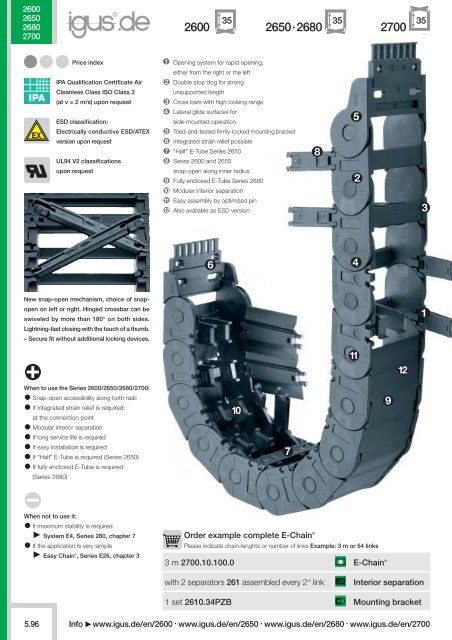
Opening system for rapid opening,<br />
either from the right or the left<br />
Double stop dog for strong<br />
unsupported length<br />
Cross bars with high locking range<br />
Lateral glide surfaces for<br />
side-mounted operation<br />
Tried-and-tested firmly-locked mounting bracket<br />
Integrated strain relief possible<br />
"Half" E-Tube Series 2650<br />
Series 2600 and 2650<br />
snap-open along inner radius<br />
Fully enclosed E-Tube Series 2680<br />
Modular interior separation<br />
Easy assembly by optimized pin<br />
Also available as ESD version<br />
New snap-open mechanism, choice of snapopen<br />
on left or right. Hinged crossbar can be<br />
swiveled by more than 180° on both sides.<br />
Lightning-fast closing with the touch of a thumb.<br />
– Secure fit without additional locking devices.<br />
When to use the Series 2600/2650/2680/2700:<br />
Snap-open accessibility along both radii<br />
If integrated strain relief is required<br />
at the connection point<br />
Modular interior separation<br />
If long service life is required<br />
If easy installation is required<br />
If "Half" E-Tube is required (Series 2650)<br />
If fully enclosed E-Tube is required<br />
(Series 2680)<br />
When not to use it:<br />
If maximum stability is required<br />
System E4, Series 280, chapter 7<br />
If the application is very simple<br />
Easy Chain ® , Series E26, chapter 3<br />
Order example complete E-Chain ®<br />
Please indicate chain-lenghts or number of links Example: 3 m or 54 links<br />
3 m 2700.10.100.0 E-Chain ®<br />
with 2 separators 261 assembled every 2 nd link<br />
Interior separation<br />
5.96<br />
Info<br />
1 set 2610.34PZB Mounting bracket<br />
www.igus.de/en/2600 · www.igus.de/en/2650 · www.igus.de/en/2680 · www.igus.de/en/2700
Installation Dimensions and Technical Data<br />
Unsupported length<br />
FL G<br />
= with straight upper run<br />
FL B<br />
= with permitted sag<br />
Further information Design, chapter 1<br />
HF<br />
H<br />
D<br />
S (FL G )<br />
S (FL B )<br />
FL G<br />
FL B<br />
S/2<br />
10.0<br />
9.0<br />
8.0<br />
7.0<br />
6.0<br />
5.0<br />
4.0<br />
3.0<br />
2.0<br />
1.0<br />
R +6 Fixed end<br />
56<br />
S<br />
FL G<br />
FL B<br />
0<br />
0 1.0 2.0 3.0 4.0 5.0<br />
Unsupported length FL G<br />
/ FL B<br />
[m]<br />
0 2 4 6 8 10<br />
R 063* 075* 100 125 150 175 200 250<br />
H 180 200 250 300 <strong>35</strong>0 400 450 550<br />
D 140 150 175 200 225 250 275 325<br />
K 3<strong>35</strong> 375 475 550 650 750 825 925<br />
D 2<br />
+25 - - 400 465 610 775 970 1150<br />
K 2<br />
- - 616 784 896 1120 1288 1624<br />
Fill weight [kg/m]<br />
Moving end<br />
Length of travel S [m]<br />
Pitch = 56 mm/link Links/m = 18 (1008 mm) Chain length = S / 2<br />
+ K<br />
* not available for Series 2680, for Series 2650 available upon request<br />
50<br />
H -50<br />
H<br />
HF = H + <strong>35</strong><br />
S = Length of travel<br />
R = Bending radius<br />
H = Nominal clearence height<br />
H F<br />
= Required clearence height<br />
H RI<br />
= Trough inner height<br />
D = Overlength E-Chain ®<br />
radius in final position<br />
K = π • R + "safety"<br />
D 2<br />
= Over length for long<br />
travels gliding<br />
K 2<br />
= Further add-on if the<br />
mounting bracket location<br />
is set lower<br />
Other installation methods<br />
Vertical, hanging ≤ 50 m<br />
Vertical, standing ≤ 3 m<br />
Side mounted, unsupp. ≤ 1 m<br />
Rotary requires further calculation<br />
Short travels -<br />
unsupported<br />
Unsupported E-Chains ® feature<br />
positive camber over short<br />
travels. This must be accounted<br />
for when specifying the clearance<br />
height H F<br />
. Please consult igus ®<br />
if space is particularly restricted.<br />
The required<br />
clearance height:<br />
H F<br />
= H + <strong>35</strong> mm<br />
(with 2,0 kg/m fill weight)<br />
2600<br />
2650<br />
2680<br />
2700<br />
<strong>35</strong><br />
E2 /000 medium<br />
Inner height: <strong>35</strong> mm<br />
Phone +49- (0) 22 03-96 49-800<br />
Fax +49- (0) 22 03-96 49-222<br />
Long travel lengths from 10 m to max. 120 m Chain length = S / 2<br />
+ K 2<br />
S<br />
S/2 S/2<br />
Moving end<br />
Fixed end<br />
D2<br />
K2<br />
Guide trough with glide bar<br />
Guide trough without glide bar<br />
Total length of guide trough<br />
In case of travels between 4 and 10 m we recommend a longer unsupported length.<br />
R<br />
HRI<br />
Gliding, long travel<br />
applications (max. 120 m)<br />
In this case the E-Chain ® upper<br />
run will be introduced in a guide<br />
trough on the lower run.<br />
We recommend to realize the<br />
engineering of such a plant by<br />
our technicians.<br />
chapter 10<br />
Speed / acceleration FL G<br />
max. 20 [m/s] / max. 200 [m/s 2 ]<br />
Speed / acceleration FL B<br />
max. 3 [m/s] / max. 6 [m/s 2 ]<br />
Gliding speed / acceleration (maximum) max. 10 [m/s] / max. 50 [m/s 2 ]<br />
Material - permitted temperature °C<br />
igumid G / -40° up to +130° C<br />
Flammability class, igumid G<br />
VDE 0304 IIC UL94 HB<br />
Technical Data<br />
C°<br />
Details of material properties<br />
chapter 1<br />
chapter 9<br />
page 5.73<br />
Info<br />
www.igus.de/en/2600 · www.igus.de/en/2650 · www.igus.de/en/2680 · www.igus.de/en/2700<br />
5.97
<strong>35</strong><br />
50<br />
<strong>35</strong><br />
50<br />
2600<br />
2700<br />
Series 2600 · 2700 - E-Chains ®<br />
Product Range<br />
igus ® E-ChainSystems ®<br />
32<br />
max.<br />
Ba<br />
Bi<br />
R<br />
Series 2600 - E-Chain ® - snap-open along inner radius<br />
Part No. Bi [mm] Ba [mm] R [mm] Bending radii Weight [kg/m]<br />
2600.05. .0 50 66 063 075 100 125 150 175 200 250 ≈ 1,17<br />
2600.06. .0 65 81 063 075 100 125 150 175 200 250 ≈ 1,24<br />
2600.07. .0 75 91 063 075 100 125 150 175 200 250 ≈ 1,30<br />
2600.09. .0 90 106 063 075 100 125 150 175 200 250 ≈ 1,37<br />
2600.10. .0 100 116 063 075 100 125 150 175 200 250 ≈ 1,39<br />
2600.12. .0 125 141 063 075 100 125 150 175 200 250 ≈ 1,48<br />
2600.15. .0 150 166 063 075 100 125 150 175 200 250 ≈ 1,62<br />
2600.17. .0 175 194 063 075 100 125 150 175 200 250 ≈ 1,85<br />
Phone +49- (0) 22 03-96 49-800<br />
Fax +49- (0) 22 03-96 49-222<br />
igus ® GmbH<br />
51147 Cologne<br />
Part No. structure<br />
2600. 05. 063. 0<br />
32<br />
max.<br />
Bi<br />
Ba<br />
R<br />
Part No. structure<br />
2700. 05. 063. 0<br />
Color<br />
black<br />
Bending<br />
radius<br />
Width<br />
Series<br />
Color<br />
black<br />
Bending<br />
radius<br />
Width<br />
Series<br />
Supplement Part No. with required radius. Example: 2600.05. 063 .0<br />
0 = standard color, other colors chapter 1 · Pitch = 56 mm/link - Links/m = 18<br />
Series 2700 - E-Chain ® - snap-open along outer radius - Standard!<br />
Part No. Bi [mm] Ba [mm] R [mm] Bending radii Weight [kg/m]<br />
2700.05. .0 50 66 063 075 100 125 150 175 200 250 ≈ 1,17<br />
2700.06. .0 65 81 063 075 100 125 150 175 200 250 ≈ 1,24<br />
2700.07. .0 75 91 063 075 100 125 150 175 200 250 ≈ 1,30<br />
2700.09. .0 90 106 063 075 100 125 150 175 200 250 ≈ 1,37<br />
2700.10. .0 100 116 063 075 100 125 150 175 200 250 ≈ 1,39<br />
2700.12. .0 125 141 063 075 100 125 150 175 200 250 ≈ 1,48<br />
2700.15. .0 150 166 063 075 100 125 150 175 200 250 ≈ 1,62<br />
2700.17. .0 175 194 063 075 100 125 150 175 200 250 ≈ 1,85<br />
Supplement Part No. with required radius. Example: 2700.05. 063 .0<br />
0 = standard color, other colors chapter 1 · Pitch = 56 mm/link - Links/m = 18<br />
Internet: www.igus.de<br />
E-mail: info@igus.de<br />
5.98<br />
Info<br />
www.igus.de/en/2600 · www.igus.de/en/2650 · www.igus.de/en/2680 · www.igus.de/en/2700
2600<br />
2650<br />
2680<br />
2700<br />
igus ® E-ChainSystems ®<br />
3<br />
Vertical Separator<br />
unassembled 260<br />
assembled 261<br />
3<br />
Vertical Separator*<br />
unassembled 260.24<br />
assembled 261.24<br />
Spacer*<br />
unassembled 205.09<br />
assembled 215.09<br />
*For side-mounted<br />
applications<br />
12<br />
24<br />
9<br />
Series 2600 · 2700 - E-Chains ® - Interior Separation<br />
Option 1: Vertical Separators and Spacer for E-Chains ®<br />
Standard subdivision (Series 2600/Series 2700) with Vertical Separator 261,<br />
for combinations with Full-Width Shelf 221.X<br />
Standard: Vertical Separators are assembled every other chain link.<br />
If a broad distance shall be kept between the separators or they have to be fixed in their position, e.g. in<br />
case of side mounted applications, separators with broad foot 261.24 or Spacer 215.09 can be used.<br />
261.24* 215.09* 261<br />
Phone +49- (0) 22 03-96 49-800<br />
Fax +49- (0) 22 03-96 49-222<br />
igus ® GmbH<br />
51147 Cologne<br />
Vert. Separator, slotted<br />
unassembled 268<br />
assembled 269<br />
Full-Width Shelf<br />
X-1<br />
t = 2,5<br />
Middle Plate<br />
unassembled 262<br />
assembled 263<br />
Slotted Separator<br />
unassembled 266<br />
assembled 267<br />
2,5<br />
10<br />
4<br />
10<br />
2,5<br />
10<br />
Option 2: Full-Width Shelves<br />
For applications involving many thin cables with similar or identical diameters<br />
for a continuing subdivision of the E-Chain ®-<br />
Vertical Separator, slotted 269 - for applications with Full-Width Shelf 221.X<br />
2,5<br />
5 5 5 5<br />
16,25 16,25<br />
221.X 269<br />
Width Part No. Part No. Width Part No. Part No.<br />
X [mm] unassembled assembled X [mm] unassembled assembled<br />
50 220.50 221.50 100 220.100 221.100<br />
65 220.65* 221.65 125 220.125 221.125<br />
75 220.75 221.75 150 220.150 221.150<br />
90 220.90* 221.90 175 220.175 221.175<br />
*upon request<br />
Option 3: Shelves for for E-Chains ®<br />
For applications involving many cables with similar or identical diameters. The Shelves can be arranged<br />
elevator-shifted with different bottoms within the entire chain width.<br />
Shelf 2210.X can be combined with Middle Plate 263, Slotted Separator 267 and Side Plate 265<br />
Option 3 "Shelves" can also be combined with option 1 "Vertical Separators".<br />
Side Plate<br />
unassembled<br />
assembled<br />
264<br />
265<br />
4<br />
7<br />
5 5 5 5<br />
min. 10<br />
2,5<br />
16,25 16,25<br />
6,25<br />
267 2210.X<br />
7,5<br />
X - 7<br />
263<br />
265<br />
Internet: www.igus.de<br />
E-mail: info@igus.de<br />
Shelf<br />
X<br />
X - 7<br />
t = 2,5<br />
Width Part No. Part No.<br />
X [mm] unassembled assembled<br />
18 2200.18 2210.18<br />
23 2200.23 2210.23<br />
28 2200.28 2210.28<br />
33 2200.33 2210.33<br />
38 2200.38 2210.38<br />
43 2200.43 2210.43<br />
48 2200.48 2210.48<br />
Width Part No. Part No.<br />
X [mm] unassembled assembled<br />
58 2200.58 2210.58<br />
68 2200.68 2210.68<br />
73 2200.73 2210.73<br />
88 2200.88 2210.88<br />
99 2200.99 2210.99<br />
124 2200.124 2210.124<br />
149 2200.149 2210.149<br />
5.100<br />
Info<br />
www.igus.de/en/2600 · www.igus.de/en/2650 · www.igus.de/en/2680 · www.igus.de/en/2700
Series 2650 · 2680 - E-Tubes - Interior Separation<br />
Option 4: Vertical Separators for E-Tubes<br />
Standard subdivision of the "Half" E-Tube (Series 2650) and the fully enclosed E-Tube (Series 2680)<br />
with Vertical Separator, slotted 26511, for combinations with Full-Width Shelf 221.X<br />
Standard: Vertical Separators are assembled every other chain link.<br />
26511<br />
Vert. Separator, slotted<br />
unassembled 26501<br />
assembled 26511<br />
4<br />
6<br />
12<br />
2600<br />
2650<br />
2680<br />
2700<br />
E2 medium<br />
Inner height: <strong>35</strong> mm<br />
Option 5: Full-Width Shelves for E-Tubes<br />
For applications involving many thin cables with similar or identical diameters<br />
for a continuing subdivision of the E-Chain ®<br />
Vertical Separator, slotted 26511 - for applications with Full-Width Shelf 221.X<br />
2,5<br />
5 5 5 5<br />
16,25 16,25<br />
221.X<br />
26511<br />
Width Part No. Part No. Width Part No. Part No.<br />
X [mm] unassembled assembled X [mm] unassembled assembled<br />
50 220.50 221.50 100 220.100 221.100<br />
65 220.65* 221.65 125 220.125 221.125<br />
75 220.75 221.75 150 220.150 221.150<br />
90 220.90* 221.90 175 220.175 221.175<br />
*upon request<br />
Full-Width Shelf<br />
X - 1<br />
t = 2,5<br />
Phone +49- (0) 22 03-96 49-800<br />
Fax +49- (0) 22 03-96 49-222<br />
Variante 6 - Shelves for E-Tubes<br />
For applications involving many cables with similar or identical diameters. The Shelves can<br />
be arranged elevator-shifted with different bottoms within the entire chain width.<br />
Shelf 2210.X can be combined with Vertical Separator, slotted 26511<br />
2,5<br />
16,25 16,25<br />
6,25<br />
7,5<br />
26511<br />
2210.X<br />
X - 7<br />
chapter 10<br />
Width Part No. Part No.<br />
Width Part No. Part No.<br />
X [mm] unassembled assembled<br />
X [mm] unassembled assembled<br />
18 2200.18 2210.18<br />
23 2200.23 2210.23<br />
58 2200.58 2210.58<br />
68 2200.68 2210.68<br />
chapter 9<br />
28 2200.28 2210.28<br />
73 2200.73 2210.73<br />
33 2200.33 2210.33<br />
38 2200.38 2210.38<br />
43 2200.43 2210.43<br />
48 2200.48 2210.48<br />
88 2200.88 2210.88<br />
99 2200.99 2210.99<br />
124 2200.124 2210.124<br />
149 2200.149 2210.149<br />
Shelf<br />
X<br />
X - 7<br />
t = 2,5<br />
page 5.73<br />
Info<br />
www.igus.de/en/2600 · www.igus.de/en/2650 · www.igus.de/en/2680 · www.igus.de/en/2700<br />
5.101
Ba + 2<br />
A<br />
A<br />
10<br />
Ba + 2<br />
2600<br />
2650<br />
2680<br />
2700<br />
2600·2650·2680·2700 Mounting Brackets, Polymer<br />
Moving end with bore<br />
A1 A2 A3 A4<br />
Possible installation conditions for assembled mounting<br />
brackets Order example "preassembled" below<br />
The Standard - option polymer - pivoting<br />
Recommended for unsupported and gliding applications<br />
Well suited for tight installation conditions<br />
Strain relief with detachable tiewrap plates<br />
Variable traverse angle for flexible assembly<br />
The twistability of the E-Chain ®<br />
and the option to assemble the<br />
mounting brackets on the fixed end and/or the moving end, enable<br />
various installation options<br />
(outer link) 26...3PZ(B)<br />
90° 53°<br />
53° 90°<br />
90°<br />
53°<br />
26...4PZ(B) Fixed end<br />
with pin (inner link)<br />
53°<br />
90°<br />
Moving end with bore<br />
A1 A2 A3 A4<br />
Possible installation conditions for assembled mounting<br />
brackets Order example "preassembled" below<br />
Option polymer - locking<br />
Recommended for unsupported and gliding applications<br />
Furthermore:<br />
At very high speed and/or acceleration<br />
If space is limited for height (the H F<br />
measurement)<br />
The twistability of the E-Chain ® and the option to assemble the<br />
mounting brackets on the fixed end and/or the moving end,<br />
enable various installation options<br />
(outer link) 26...1PZ(B)<br />
26...2PZ(B) Fixed end<br />
with pin (inner link)<br />
Dimensions and<br />
order configurations<br />
Strain relief is possible on the<br />
moving end and/or the fixed end.<br />
Part No. structure (pivoting)<br />
26...3PZ(B) Standard! (pivoting)<br />
Standard! (pivoting) 26...4PZ(B)<br />
26...1PZ(B) (locking)<br />
(locking) 26...2PZ(B)<br />
Moving end<br />
16/90° 17 17<br />
Fixed end<br />
2605. 34 PZB A1<br />
igus ® GmbH<br />
51147 Cologne<br />
A…must be indicated<br />
on preassembled configurations<br />
With assembled strain<br />
relief tiewrap plates<br />
Full set<br />
pivoting = 34<br />
Mounting brackets for<br />
selected chain type<br />
Full set, for both ends:<br />
2605. 34 PZB +tiewrap plate<br />
Single-part order:<br />
2605. 3 PZB +tiewrap plate<br />
Mounting bracket with bore<br />
2605. 4 PZB +tiewrap plate<br />
Mounting bracket with pin<br />
40<br />
t = 8<br />
6,1<br />
17 17 8<br />
2<br />
54<br />
54<br />
40<br />
t = 8<br />
Internet: www.igus.de<br />
E-mail: info@igus.de<br />
Part No. structure (locking)<br />
2605. 12 PZB A1<br />
A…must be indicated<br />
on preassembled configurations<br />
With assembled strain<br />
relief tiewrap plates<br />
Full set<br />
locking = 12<br />
Mounting brackets for<br />
selected chain type<br />
Full set, for both ends:<br />
2605. 12 PZB +tiewrap plate<br />
Single-part order:<br />
2605. 1 PZB +tiewrap plate<br />
Mounting bracket with bore<br />
2605. 2 PZB +tiewrap plate<br />
Mounting bracket with pin<br />
For Part No. Part No. with Part No. Dim. A<br />
E-Chain ® full set with tiewrap plate + full set without [mm]<br />
tiewrap plate 10 cable tiewraps tiewrap plate<br />
2600 – 2700.05 2605. PZB 2605. PZBK1 2605. PZ 30<br />
2600 – 2700.06 2606. PZB 2606. PZBK1 2606. PZ 45<br />
2600 – 2700.07 2607. PZB 2607. PZBK1 2607. PZ 55<br />
2600 – 2700.09 2609. PZB 2609. PZBK1 2609. PZ 70<br />
2600 – 2700.10 2610. PZB 2610. PZBK1 2610. PZ 80<br />
2600 – 2700.12 2612. PZB 2612. PZBK1 2612. PZ 105<br />
2600 – 2700.15 2615. PZB 2615. PZBK1 2615. PZ 130<br />
2600 – 2700.17 2617. PZB 2617. PZBK1 2617. PZ 155<br />
Please add the Part No. with the requested index - 34 for the pivoting configuration<br />
e.g. 2605. 34 PZB or 12 for the locking configuration e.g. 2605. 12 PZB<br />
For the preassembled mode please add the index A1 ... A4 e.g. 2605. 34 PZB A1<br />
5.102<br />
Info<br />
www.igus.de/en/2600 · www.igus.de/en/2650 · www.igus.de/en/2680 · www.igus.de/en/2700
2600·2650·2680·2700: Mounting Brackets KMA*<br />
2600<br />
2650<br />
2680<br />
2700<br />
Option KMA - locking<br />
* KMA's are only deliverable with cross bars at the moment (no<br />
lids and bottoms). The closing mechanism of the bars at the<br />
KMA can differently fail than the normal E2/000 closing.<br />
Option – integrated C profile strain relief device with Chainfix clip<br />
Moving end with bore<br />
(outer link) 26000....1<br />
53°<br />
or strain relief tiewrap plates<br />
53°<br />
C profile mountable in the inner or outer radius of the E-Chain ®<br />
53°<br />
Bolted connection outside of chain cross-section<br />
Recommended for vertical hanging / standing applications<br />
At very high speed and acceleration<br />
53°<br />
26000...2 Fixed end<br />
The attachment variants<br />
arising automatically by<br />
the choice of the KMA<br />
Standard position<br />
C-Profile<br />
Universal mountable with attachment capability on all sides<br />
* KMA = Polymer Metal Mounting Bracket<br />
with pin (inner link)<br />
mounting bracket<br />
Moving end with bore<br />
Option KMA - locking<br />
(outer link) 26100...1<br />
Option – integrated C profile strain relief device with Chainfix clip<br />
or strain relief tiewrap plates<br />
C profile mountable in the inner or outer radius of the E-Chain ®<br />
Bolted connection outside of chain cross-section<br />
The attachment variants<br />
Recommended for vertical hanging / standing applications<br />
At very high speed and acceleration<br />
26100...2 Fixed end<br />
arising automatically by<br />
the choice of the KMA<br />
Standard position<br />
C-Profile<br />
Universal mountable with attachment capability on all sides<br />
with pin (inner link)<br />
mounting bracket<br />
26000...1 (pivoting) (pivoting) 26000...2<br />
26100...1 (locking) (locking) 26100...2<br />
Moving end<br />
Fixed end<br />
73 73<br />
28,5<br />
28,5<br />
Dimensions and<br />
order configurations<br />
Part No. structure (pivoting)<br />
26000. 05. 12 C A<br />
A…must be indicated<br />
on preassembled configurations<br />
integrated C-Profile<br />
B<br />
A<br />
Bi - 5<br />
ø 5,5<br />
ø 5,5<br />
Bi - 5<br />
A<br />
For Part No. full set Part No. full set Dim. A Dim. B<br />
E-Chain ® with without [mm] [mm]<br />
C-Profile<br />
C-Profile<br />
2600 – 2700.05 .05.12C .05.12 58 69<br />
2600 – 2700.06 on request<br />
on request<br />
– –<br />
2600 – 2700.07 .07.12C .07.12 83 94<br />
2600 – 2700.09 on request<br />
on request<br />
– –<br />
2600 – 2700.10 .10.12C .10.12 108 119<br />
2600 – 2700.12 .12.12C .12.12 133 144<br />
2600 – 2700.15 .15.12C .15.12 158 169<br />
2600 – 2700.17 .17.12C .17.12 183 194<br />
Please add the Part No. with the requested index - 2600 for the pivoting configuration<br />
e.g. 26000 .05.12 or 2700 for the locking configuration e.g. 26100 .05.12<br />
For the preassembled mode please add the index A e.g. 26000 .05.12 A<br />
B<br />
19<br />
A<br />
26100. 05. 12 C A<br />
Full set<br />
Width<br />
KMA pivoting for<br />
selected chain type<br />
Full set, for both ends:<br />
26000. 05. 12 C (with C-Profile)<br />
Single-part order:<br />
26000. 05. 1 C (with C-Profile)<br />
Mounting bracket with bore<br />
26000. 05. 2 C (with C-Profile)<br />
Mounting bracket with pin<br />
Part No. structure (locking)<br />
A…must be indicated<br />
on preassembled configurations<br />
integrated C-Profile<br />
Full set<br />
Width<br />
KMA locking for<br />
selected chain type<br />
Full set, for both ends:<br />
26000. 05. 12 C (with C-Profile)<br />
Single-part order:<br />
26100. 05. 1 C (with C-Profile)<br />
Mounting bracket with bore<br />
26100. 05. 2 C (with C-Profile)<br />
Mounting bracket with pin<br />
chapter 10<br />
chapter 9<br />
page 5.73<br />
Info<br />
www.igus.de/en/2600 · www.igus.de/en/2650 · www.igus.de/en/2680 · www.igus.de/en/2700<br />
5.103
2600<br />
2650<br />
2680<br />
2700<br />
2600 · 2650 · 2680 · 2700 Steel Mounting Brackets<br />
Steel mounting bracket - locking<br />
Locked connections<br />
One part for all chain widths<br />
Electrically conductive<br />
Bolted connection outside of chain cross-section possible<br />
Moving end with bore<br />
(outer link) 260.1<br />
Possible installation conditions -<br />
Further installation angles installation sketch<br />
260.2 Fixed end<br />
with pin (inner link)<br />
Dimensions and<br />
order configurations<br />
260.1 260.2* 260.1 260.2<br />
Phone +49- (0) 22 03-96 49-800<br />
Fax +49- (0) 22 03-96 49-222<br />
*pivoting with no stop, (360°)<br />
B<br />
3<br />
7 7<br />
56<br />
24<br />
56<br />
3<br />
9<br />
B<br />
A<br />
3<br />
7 7<br />
56<br />
24<br />
56<br />
3<br />
9<br />
A<br />
igus ® GmbH<br />
51147 Cologne<br />
260. 12 Full set, 4 parts<br />
2 with pin / 2 with bore<br />
Single-part order:<br />
260. 1 Mounting bracket<br />
with bore, 1 part left / right<br />
260. 2 Mounting bracket with<br />
pin, 1 part left / right<br />
For Part No. Dim. A Dim. B<br />
E-Chain ® full set [mm] [mm]<br />
2600 – 2700.05 260. 12<br />
37 83<br />
2600 – 2700.06 260. 12<br />
52 98<br />
2600 – 2700.07 260. 12<br />
62 108<br />
2600 – 2700.09 260. 12<br />
77 123<br />
2600 – 2700.10 260. 12<br />
87 133<br />
2600 – 2700.12 260. 12<br />
112 158<br />
2600 – 2700.15 260. 12<br />
137 183<br />
2600 – 2700.17 260. 12<br />
163 209<br />
Internet: www.igus.de<br />
E-mail: info@igus.de<br />
5.104<br />
Info<br />
www.igus.de/en/2600 · www.igus.de/en/2650 · www.igus.de/en/2680 · www.igus.de/en/2700
8<br />
6<br />
2<br />
2600 · 2650 · 2680 · 2700 - Strain Relief<br />
Strain Relief for polymer mounting brackets (pivoting or locking)<br />
The strain relief plates can be snapped directly onto the mounting bracket without additional hardware.<br />
When the mounting brackets are bolted into place, the strain relief plates are also firmly connected to the<br />
machine surface. No separate installation is necessary. Cable tiewraps secure cables using the "teeth"<br />
of the tiewrap plate for time-saving, effective strain relief.<br />
Tiewrap No. of Dim. C Dim. B Center<br />
plate teeth n [mm] [mm] bore<br />
3050.ZB 5 50 30 –<br />
3075.ZB 7 75 55 –<br />
3100.ZB 10 100 80 –<br />
3115.ZB 11 115 95 –<br />
3125.ZB 12 125 105 –<br />
3150.ZB 15 150 130 –<br />
3175.ZB 17 175 155 –<br />
3200.ZB 20 200 180 +<br />
3225.ZB 22 225 205 +<br />
3250.ZB 25 250 230 +<br />
(– = no / + = yes)<br />
Cable tiewraps as individual part<br />
2050.Z 60<br />
6.2<br />
Tiewrap plate as individual<br />
part - Series 3000<br />
As individual component screwed on KMA. Can<br />
be plugged in the mounting brackets, more Details<br />
chapter 10<br />
C<br />
B<br />
2 8<br />
(n-1) x 10<br />
Cable tiewraps (100-piece bag) Width x length max. Ø Tensile strength<br />
CFB.001 4,8 x 150 mm 36 mm 222 N<br />
"Double" strain relief<br />
12/90°<br />
2<br />
12<br />
18<br />
If an E-Chain ®<br />
is harnessed with a very large number of cables, strain relief may be necessary at two<br />
levels. Our 2050.Z strain relief system was developed for this purpose. It can be placed in any position<br />
along the E-Chain ® . As required, the 2050.Z strain relief system is simply clamped onto the crossbar of<br />
the chain link. No additional installation elements are needed.<br />
Part No.<br />
Width - strain selief system [mm]<br />
44<br />
* More widths in preparation<br />
Single tiewrap plate<br />
28<br />
<strong>35</strong><br />
Shown assembled<br />
2600<br />
2650<br />
2680<br />
2700<br />
E2 medium<br />
Inner height: <strong>35</strong> mm<br />
Phone +49- (0) 22 03-96 49-800<br />
Fax +49- (0) 22 03-96 49-222<br />
Strain relief for steel mounting brackets<br />
Clip-on connection is not possible with steel mounting brackets. In this case, the tiewrap plates must be<br />
bolted directly into separate bore holes in front of the mounting bracket. Alternatively the tiewrap plates<br />
30XX.Z and ZS can be also used here. strain relief, chapter 10.<br />
Strain relief separator<br />
Separator with integrated strain relief for the use in the first or last chain link. Individual part for the manufacturing<br />
of switchgear cabinets or for the assembly of machines. Easy to assemble without any screws.<br />
Part No. Number of teeth For Series<br />
262.Z 3 2600/2700<br />
chapter 10<br />
Chainfix strain relief C-profile-solutions - more Details chapter 10<br />
chapter 9<br />
Chainfix clamps made<br />
of steel or stainless steel<br />
Chainfix Clips -<br />
modular, snap-on<br />
Chainfix Nugget with preharnessed<br />
cable strap<br />
Chainfix - tiewrap plates<br />
with clip-on connection<br />
Other strain relief elements -<br />
optional chapter 10<br />
page 5.73<br />
Info<br />
www.igus.de/en/2600 · www.igus.de/en/2650 · www.igus.de/en/2680 · www.igus.de/en/2700<br />
5.105
2600<br />
2650<br />
2680<br />
2700<br />
Part No. 972.30.SL and 972.32.SL- Trough height: 117 mm<br />
Aluminum "SuperTrough" - Basic Version<br />
Ba = Outer width E-Chains ® / E-Tube<br />
Bi = Inner width E-Chains ® / E-Tube<br />
ha = Outer height E-Chains ® / E-Tube<br />
H Ri<br />
= Inner trough height<br />
H Ra<br />
= Outer trough height<br />
B Ri<br />
= Inner trough width depends on dim. Ba<br />
B Ra<br />
= Outer trough width<br />
n Mon<br />
= Number of installation sets (left/right)<br />
= Number of troughs sets (left/right)<br />
n Ri<br />
!<br />
Phone +49- (0) 22 03-96 49-800<br />
Fax +49- (0) 22 03-96 49-222<br />
igus ® GmbH<br />
51147 Cologne<br />
H Ri<br />
≥ 2 • ha<br />
B Ri<br />
≥ Ba + 4<br />
= Guide trough set = Glide bar<br />
= Installation set "Basic" = C-Profile<br />
Installation set "Basic"<br />
with C-Profile<br />
Bottom Clamp attached optionally<br />
inwards or outwards<br />
2700.05.200.0 Order example<br />
Part No. Part No.<br />
B Ri<br />
attached attached<br />
[mm] inwards outwards<br />
.05 70 – 960.30.175<br />
.06 85 960.30.150 960.30.200<br />
.07 95 960.30.150 960.30.200<br />
.09 110 960.30.175 960.30.225<br />
.10 120 960.30.175 960.30.225<br />
.12 145 960.30.200 960.30.250<br />
.15 170 960.30.225 960.30.275<br />
.17 198 960.30.250 960.30.300<br />
Insert for the installation set<br />
"Heavy Duty": 972.50.XXX<br />
instead of (960.30.XXX) on the<br />
right column "attached outwards"<br />
31<br />
22<br />
Bottom clamp<br />
attached optionally<br />
inwards or<br />
outwards<br />
M6 x16<br />
B Ra<br />
B Ri ≥ Ba + 4<br />
11<br />
Ba<br />
Bi<br />
2<br />
ha<br />
50<br />
12<br />
4,9<br />
Length of the C-profile according to dimension B Ri<br />
27<br />
see table<br />
Order example: Length of travel 30 m - Center mounted<br />
for Series 2700.06.200.0 with B Ri<br />
= 85<br />
Guide trough set (set of 2 trough side parts, incl. glide strips) without glide bar<br />
Order text: 16 m Guide trough without glide bar (8 x 2 m sections) Part No.<br />
Guide trough set (set of 2 trough side parts, incl. glide strips) with glide bar<br />
Order text: 16 m Guide trough with glide bar (8 x 2 m sections)<br />
Installation set "Basic" complete (Guide trough-sets + 1)<br />
Order text: 17 Installation sets "Basic"<br />
Part No.<br />
18<br />
H Ri ≥ 2 x ha<br />
H Ra = 117<br />
Components, trough "Basic": Trough side parts, aluminum, 2 m<br />
Glide bar, plastic, 2 m Glide strips, plastic, 2 m (without glide strips on<br />
request) Optional: Silencer profile, rubber Components, installation<br />
set "Basic": Bottom clamp, aluminum C-profile, steel galvanized<br />
Screw M6 x16 Sliding nut M6 Interface connector, plastic<br />
972.30.SL<br />
972.32.SL<br />
Part No. 960.30. 150<br />
Principle sketch: Number of installation sets which have to be installed<br />
n Mon = n Ri + 1<br />
n Ri x 1998 mm<br />
Other guide trough systems<br />
Internet: www.igus.de<br />
E-mail: info@igus.de<br />
5.106<br />
"Heavy Duty" for the fastidiously<br />
construction with<br />
glide bar and dampening<br />
profiles chapter 9<br />
"Steel trough" very stable<br />
and robust guide trough<br />
out of steel, 2 pieces,<br />
adjustable on chain width<br />
chapter 9<br />
"Tubular trough" resistant<br />
against dirt – wear is<br />
falling down, easy and fast<br />
assembly chapter 9<br />
"Snap in trough" easy<br />
and fast assembly, favorable<br />
price due to simple<br />
structure, narrow design<br />
chapter 9<br />
Details about Alu "Super Trough" and "Heavy Duty" version as<br />
well as further guidance possibilities chapter 9, guide troughs


