

ELZ 10 - OEM Automatic AB
ELZ 10 - OEM Automatic AB
ELZ 10 - OEM Automatic AB

Create successful ePaper yourself
Turn your PDF publications into a flip-book with our unique Google optimized e-Paper software.
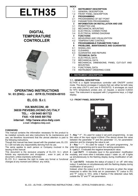
ELTH35<br />
DIGITAL<br />
TEMPERATURE<br />
CONTROLLER<br />
INDEX<br />
1 INSTRUMENT DESCRIPTION<br />
1.1 GENERAL DESCRIPTION<br />
1.2 FRONT PANEL DESCRIPTION<br />
2 PROGRAMMING<br />
2.1 PROGRAMMING OF SET POINT<br />
2.2 PARAMETERS PROGRAMMING<br />
3 INFORMATION ON INSTALLATION AND USE<br />
3.1 PERMITTED USE<br />
3.2 MECHANICAL MOUNTING<br />
3.3 ELECTRICAL CONNECTIONS<br />
3.4 ELECTRICAL WIRING DIAGRAM<br />
4 FUNCTIONS<br />
4.1 MEASURING AND VISUALIZATION<br />
4.2 TEMPERATURE CONTROL<br />
5 PROGRAMM<strong>AB</strong>LE PARAMETERS T<strong>AB</strong>LE<br />
6 PROBLEMS , MAINTENANCE AND GUARANTEE<br />
6.1 SIGNALLING<br />
6.2 CLEANING<br />
6.3 GUARANTEE AND REPAIRS<br />
7 TECHNICAL DATA<br />
7.1 ELECTRICAL DATA<br />
7.2 MECHANICAL DATA<br />
7.3 MECHANICAL DIMENSIONS, PANEL CUT-OUT AND<br />
MOUNTING<br />
7.4 FUNCTIONAL DATA<br />
7.5 INSTRUMENT ORDERING CODE<br />
1 - INSTRUMENT DESCRIPTION<br />
OPERATING INSTRUCTIONS<br />
Vr. 03 (ENG) - cod.: ISTR ELTH35EN-08<strong>10</strong>3<br />
EL.CO. S.r.l.<br />
1.1 - GENERAL DESCRIPTION<br />
ELTH35 is a digital temperature controller with ON/OFF control<br />
mode. The device envisages 2 outputs that can either be both relay<br />
or one relay (OUT1) and one 0-<strong>10</strong>V(OUT2). It envisages an input<br />
for NTC temperature probes and, on request, a second 4-20mA<br />
input. The instrument is equipped with 2 programme keys, a 2-digit<br />
display.<br />
1.2 - FRONT PANEL DESCRIPTION<br />
VIA MARCONI, 49<br />
36030 PIEVEBELVICINO (VI) ITALY<br />
TEL.: +39 0445 661722<br />
FAX: +39 0445 661792<br />
internet : http:\\www.elco-italy.com<br />
e-mail: info@elco-italy.com<br />
FOREWORD<br />
This manual contains the information necessary for the product to<br />
be installed correctly and also instructions for its maintenance and<br />
use; we therefore recommend that the utmost attention is paid to<br />
the following instructions.<br />
Though this manual has been issued with the greatest care, EL.CO.<br />
S.r.l.will not take any responsibility deriving from its use.<br />
The same applies to each person or Company involved in the<br />
issuing of this manual.<br />
This document is the exclusive property of EL.CO. S.r.l. which<br />
forbids any reproduction and divulgation , even in part, of the<br />
document, unless expressly authorized.<br />
EL.CO. S.r.l. reserves the right to make any formal or functional<br />
changes at any moment and without any notice.<br />
1 - Key “ +” : It’s used for output 2 set point programming , to see<br />
the value of the input signal 4-20mA (The device shows the value<br />
between the parameter "I" and the parameter “J”), for parameters’<br />
selection and for changing the value to set.<br />
2 – Key “ – “ : It’s used for output 1 set point programming , for<br />
enter the programming and to save the working parameters.<br />
3 - Led L1 : It indicates the negative temperature value.<br />
4 - Led OUT1 : It indicates input in the parameters’ modification<br />
modality, and more other it indicates output 1 state: on, off. It lights<br />
up simultaneously to the flashing display during modification of setpoint<br />
1.<br />
5 - Led OUT2 : Indicates the status of output 2: on -off whit relay<br />
output. It switches on simultaneously with the flashing display during<br />
modification of set-point 2<br />
Instead, when the output is at 0-<strong>10</strong>V it remains on when the range<br />
measured is within the limits set on parameters "E" (value to 0V)<br />
and "F" (value to <strong>10</strong>V), while it flashes if the detected value falls<br />
outside the "E" and "F" set parameters.<br />
EL.CO. –ELTH35 – OPERATING INSTRUCTIONS – VR03 – ISTR ELTH35EN-08<strong>10</strong>3 – PAG.1
2 - PROGRAMMING<br />
2.1 - PROGRAMMING OF THE SET POINT<br />
Press the “ - “ button for setting output 1 set point then release it,<br />
the flashing display will visualize the programmed value and<br />
“ out1” led will light up simultaneously to indicate that we are<br />
programming set point 1.<br />
To modify it, use the button “ + “ to increase or “ – “ to decrease<br />
the value .<br />
Press the “ + “ button to programme output 2 set point then release<br />
it, the flashing display will visualize the set value and<br />
“ out2” led will light up simultaneously to indicate that it’s<br />
programming set point 2. To modify it, use the button “ + “ to<br />
increase or “ – “ to decrease the value . Should the device be<br />
equipped with a second 4-20mA input to be used for the setting of<br />
the OUT2 output’s set point, proceed as follows:<br />
press button " + " and the device will show the value of the 4-20mA<br />
input for 3 seconds (The device shows the value between the<br />
parameter "I" and the parameter “J”), if during this time the button<br />
gets pressed again, the setting of the relative set point as described<br />
above will be possible, otherwise the device will resume display of<br />
the temperature measured by the probe.<br />
These buttons work with one digit steps but if you keep them<br />
pressed more than one second the value increases or decreases in<br />
a quick way.<br />
Exit from the Set mode happens automatically without pressing any<br />
button for about 5 seconds, then the display will go back to the<br />
normal mode of operation.<br />
The maximum value of set point that we can code, depends if we<br />
use instrument’s or external probe and on minimum or maximum<br />
programmed differential.<br />
Instrument’s probe: min.-20°…..max +65°C<br />
External probe: min.-35°….max+98°C<br />
Maximum programmable value=set point + positive differential<br />
Minimum programmable value=set point - negative differential<br />
Example: with 5°C positive differential, the maximum programmable<br />
set-point will be of 60°C with probe on instrument and 93°C with<br />
external probe.<br />
With 5°C negative differential, the minimum programmable set-point<br />
will be of -15°C with probe on instrument and -30°C with external<br />
probe. Should the device be equipped with the second input (4-<br />
20mA), which will always work at the second output OUT2, the<br />
value of the relay OUT2 output’s set point will fall between the<br />
values set on parameters "I" (input value at 4mA) and "J" (input<br />
value at 20mA).<br />
The minimum and maximum settable values of the OUT2 output’s<br />
set point depends on the values of parameters "I" and "J" and of<br />
parameter "L" (4-20mA input offset).<br />
Minimum set point value: set-point - input offset 4-20mA (“L")<br />
Maximum set point value: set-point + input offset 4-20mA (“L")<br />
If the OUT2 output is in the range 0-<strong>10</strong>V, the setting of the relative<br />
set point will not be possible, but output OUT2 will change from 0 to<br />
<strong>10</strong>V according to the measurement of the temperature probe or<br />
according to the second 4-20mA input signal and, therefore,<br />
according to the values set for parameters "E" (value to 0V) and "F"<br />
(value to <strong>10</strong>V). With the second 4-20mA input, the values of<br />
parameters "E" and "F" will always be in line with parameters "I" (4-<br />
20mA minimum value) and "J" (4-20mA maximum value). With the<br />
0-<strong>10</strong>V output, parameter "L" (4-20mA input offset) will only calibrate<br />
the input signal. By pressing the " + " button, the value of the 4-<br />
20mA input signal will be displayed for 3 seconds(The device shows<br />
the value between the parameter "I" and the parameter “J”).<br />
2.2 - PARAMETERS PROGRAMMING<br />
To enter the operating parameters of the instrument, we need to<br />
press “ + “ and “ – “ buttons simultaneously and to keep them<br />
pressed for about 3 seconds, after whom the display will visualize<br />
the code which identified the first parameter and with “ + “ button<br />
will be possible to select the parameter that we intend to modify.<br />
Once we have selected the whished parameter, press “ – “ button,<br />
“ out1 “ led will light up and the display will visualize parameter<br />
code and its programming which could be modified by “ + “<br />
button.<br />
After having programmed the whished value, press “ - “ button :<br />
the new value will be saved and the display will show once again the<br />
code of the selected parameter and “ out1 ” led will turn off.<br />
Working on “ + “ button then, it will be possible to select another<br />
parameter and modify it as described above.<br />
To exit the programming mode keep “ + “ and “ – “buttons<br />
pressed simultaneously for 3 seconds till to exit the programming<br />
mode. During programming of set point (flashing display ) it’s not<br />
possible to enter parameters’ setting.<br />
3 - INFORMATION ON INSTALLATION AND USE<br />
3.1 - PERMITTED USE<br />
The instrument CANNOT be used in dangerous environments<br />
(flammable or explosive) without adequate protection. The installer<br />
must ensure that EMC rules are respected, also after the instrument<br />
installation, if necessary using proper filters. Whenever a failure or a<br />
malfunction of the device may cause dangerous situations for<br />
persons, thing or animals, please remember that the plant has to be<br />
equipped with additional devices which will guarantee safety.<br />
3.2 - MECHANICAL MOUNTING<br />
The instrument, in case 1 DIN Modules, is designed for mounting on<br />
DIN OMEGA rail.<br />
Avoid placing the instrument in environments with very high<br />
humidity levels or dirt that may create condensation or introduction<br />
of conductive substances into the instrument.<br />
Ensure adequate ventilation to the instrument and avoid installation<br />
in containers that house devices which may overheat or which may<br />
cause the instrument to function at a higher temperature than the<br />
one permitted and declared.<br />
Connect the instrument as far away as possible from sources of<br />
electromagnetic disturbances such as motors, power relays, relays,<br />
solenoid valves, etc.<br />
3.3 - ELECTRICAL CONNECTION<br />
Carry out the electrical wiring by connecting only one wire to each<br />
terminal, according to the following diagram, checking that the<br />
power supply is the same as that indicated on the instrument and<br />
that the load current absorption is no higher than the maximum<br />
electricity current permitted.<br />
As the instrument is built-in equipment with permanent connection<br />
inside housing, it is not equipped with either switches or internal<br />
devices to protect against overload of current: the installation will<br />
include an overload protection and a two-phase circuit-breaker,<br />
placed as near as possible to the instrument, and located in a<br />
position that can easily be reached by the user and marked as<br />
instrument disconnecting device which interrupts the power supply<br />
to the equipment.<br />
It is also recommended that the supply of all the electrical circuits<br />
connected to the instrument must be protect properly, using devices<br />
(ex. fuses) proportionate to the circulating currents.<br />
It is strongly recommended that cables with proper insulation,<br />
according to the working voltages and temperatures, be used.<br />
Furthermore, the input cable of the probe has to be kept separate<br />
from line voltage wiring. If the input cable of the probe is screened, it<br />
has to be connected to the ground with only one side.<br />
For the power supply it’s recommended to use an external<br />
transformer TRE, or with equivalent features, and to use only one<br />
transformer for each instrument because there is no insulation<br />
between supply and input. For the probe it is recommended to<br />
use an isolated NTC.<br />
We recommend that a check should be made that the parameters<br />
are those desired and that the application functions correctly before<br />
connecting the outputs to the actuators so as to avoid<br />
malfunctioning that may cause irregularities in the plant that could<br />
cause damage to people, things or animals.<br />
EL.CO. –ELTH35 – OPERATING INSTRUCTIONS – VR03 – ISTR ELTH35EN-08<strong>10</strong>3 – PAG.2
EL.CO. S.r.l. and its legal representatives do not assume any<br />
responsibility for any damage to people, things or animals<br />
deriving from violation, wrong or improper use or in any case<br />
not in compliance with the instrument’s features.<br />
Temp.<br />
SP<br />
B / E Negative differential<br />
3.4 - ELECTRICAL WIRING DIAGRAM<br />
PS. The neutral must always be connected to terminal A1<br />
OUT<br />
ON<br />
off<br />
ON<br />
off<br />
ON<br />
time<br />
12-30VAC/DC<br />
200-240VAC<br />
A1<br />
INPUT 4-20mA NTC (isolated)<br />
- + 1 2 OUT2<br />
0V <strong>10</strong>V<br />
OUT 1<br />
8A-250V AC1<br />
8A-250V AC1<br />
Temp.<br />
SP<br />
OUT<br />
ON<br />
off<br />
ON<br />
off<br />
ON<br />
time<br />
C / F Positive differential<br />
4 - FUNCTIONS<br />
A2 18 15 16<br />
28 25 26<br />
4.1 - MEASURING AND VISUALIZATION<br />
The instrument works with a NTC probe( <strong>10</strong>K 25°C) and if required<br />
also with a second input of 4-20mA.<br />
Through “A” par. it’s possible to choice whether working with probe<br />
on the instrument or with an external probe ( AI : instrument one–<br />
AE : external one).<br />
If during the setting of parameters we switch from external probe<br />
“AE” to the instrument’s one “AI”, it’s necessary to programme the<br />
set point once again, seeing that operating temperature range<br />
changes depending on the way of using the probe.<br />
The instrument allows the measure’s calibration, which can be used<br />
in order to adjust the device once again by “ H ”parameter<br />
following up application’s necessities.<br />
Should the device have been ordered with the second 4-20mA<br />
input, through parameter "I" it will be necessary to set the relevant<br />
value in the position of the beginning of scale (4mA) and with<br />
parameter "J" the value in the position of full scale (20mA). The 4-<br />
20mA analog signal may come from any equipment that would<br />
envisage this output, so it could be referred to a temperature, a<br />
humidity signal etc.<br />
The second 4-20mA input will always and only work in line with<br />
output OUT2, while output OUT1 will always work in line with the<br />
NTC probe. The device allows calibration of the input signal (4-<br />
20mA) measurement according to the application’s requirements,<br />
by means of parameter "L".<br />
PS. Wait 3 minutes before checking the correct measurement of<br />
temperature.<br />
4.2 - TEMPERATURE CONTROL<br />
a) OUT1 and OUT2 relays operation<br />
The regulating mode of instrument is ON/OFF type. It works on<br />
OUT1 and OUT2 output depending on probe’s measure, on<br />
programmed Set Point 1 and Set Point 2 and on negative “ B “ or<br />
positive “ C “ operating differential for OUT1 and negative “ E “<br />
or positive “ F “ for OUT2.<br />
When it occurs an error for short circuit or for interruption of the<br />
probe, the device is going to deactivate the output and the display<br />
will flash visualizing two dashes “ - - “.<br />
Through “ D “ parameter we can regulate operating mode of<br />
output 1 relay till reaching the set point: : OFF “ D1 “ or ON “ D2 “<br />
. Through “ G “ parameter we can regulate operating mode of<br />
output 2 relay till reaching the set point: : OFF “ G1 “ or ON<br />
“ G2 “ .<br />
b) Operation with OUT1 relay and OUT2 at 0-<strong>10</strong>V<br />
Only output OUT2 could be at 0-<strong>10</strong>V, while output OUT1 will always<br />
be at relay.<br />
For the operation of output OUT1, please refer to point a) above.<br />
Output OUT2 will vary from 0 to <strong>10</strong>V according to the measurement<br />
of the temperature probe or to the second input signal from 4-20mA<br />
and of the values set in parameters "E" (value to 0V) and "F" (value<br />
to <strong>10</strong>V).<br />
Example: if in parameter "E" we set a value of 20°C, and in<br />
parameter "F" we set value 60°C, output OUT2 will vary from 0 to<br />
<strong>10</strong>V in line with the temperature detected of 20°C and 60°C. Led<br />
OUT2 will always remain on until the temperature detected falls<br />
between the values set for parameters "E" and "F". Should the<br />
temperature detected by the probe be lower than the value set in<br />
parameter "E", output OUT2 will remain stable at 0V, while LED<br />
OUT2 will flash. Should the temperature detected by the probe be<br />
higher than the value set in parameter "F", output OUT2 will remain<br />
stable at <strong>10</strong>V, while LED OUT2 will flash.<br />
Through parameter "G" it will be possible to adjust the operating<br />
mode of output 0-<strong>10</strong>V(G1 = direct 0-<strong>10</strong>V / G2 = inverse <strong>10</strong>-0V).<br />
c) Operation with second 4-20mA input.<br />
The second 4-20mA input will always and only work in line with<br />
output OUT2, while output OUT1 will always work in line with the<br />
NTC probe.<br />
For the operation of output OUT1, please refer to point a) above.<br />
For the second 4-20mA input, its value needs to be set through<br />
parameter "I" in line with the beginning of scale (4mA) and with<br />
parameter "J", its value should be set in the full scale position<br />
(20mA). If the OUT2 output is designed as relay the setting of the<br />
set point must be carried out within the values set for parameters "I"<br />
and "J". To set the OUT2 output’s set point, see 2.1. The mode<br />
used to adjust output OUT2 is of the ON/OFF type. Through<br />
parameters "E" and "F" the negative and positive differential will be<br />
set, while with parameter "G", the operating mode of relay output<br />
OUT2 will likewise be set. When the value of the input signal 4-<br />
20mA reaches the set value of the OUT2 output’s set point, the<br />
output itself will change status.<br />
If output OUT2 is designed in the 0-<strong>10</strong>V range, it will vary in a linear<br />
way according to the 4-20mA input. Output OUT2 will vary from 0 to<br />
<strong>10</strong>V according to the 4-20mA input and to the values set in<br />
parameters "E" (value to 0V) and "F" (value to <strong>10</strong>V). The minimum<br />
value settable in parameter "E" may not, in any case, differ from that<br />
set in parameter "I" (4mA beginning of scale value). The maximum<br />
value settable in parameter "F" may not, in any case, differ from that<br />
set in parameter "J" (20mA full scale value).<br />
EL.CO. –ELTH35 – OPERATING INSTRUCTIONS – VR03 – ISTR ELTH35EN-08<strong>10</strong>3 – PAG.3
Through parameter "G" it will be possible to adjust the operating<br />
mode of output 0-<strong>10</strong>V (G1 = direct 0-<strong>10</strong>V / G2 = inverse <strong>10</strong>-0V).<br />
5 - PROGRAMM<strong>AB</strong>LE PARAMETERS T<strong>AB</strong>LE<br />
Here below is a description of all the parameters available on the<br />
instrument.<br />
Par. Descrizione Range Def. Note<br />
1 Probe range<br />
A I : On the instrument<br />
E : Outside<br />
-20….+65°C<br />
-35….+98°C<br />
I<br />
2 B negative differential<br />
(OUT1)<br />
3 C positive differential<br />
(OUT1)<br />
4 D Output relay operation<br />
( OUT1)<br />
D1=OFF / D2=ON<br />
negative differential<br />
(OUT2)<br />
5 E<br />
6 F<br />
7 G<br />
NTC Input<br />
4-20mA Input<br />
NTC Input<br />
4-20mA Input<br />
Temperature value<br />
corresponding to 0V<br />
(OUT2 0-<strong>10</strong>V)<br />
0 – 9 °C 0°C<br />
0 – 9 °C 0°C<br />
D1<br />
D2<br />
D1<br />
0 – 9 °C 0°C<br />
NTC Interna<br />
-20….+65°C<br />
NTC Esterna<br />
-35….+98°C<br />
0°C<br />
Minimum value OUT 2<br />
0-<strong>10</strong>V corresponding to<br />
the minimum value of 4-<br />
20mA input ( I ) - - - 0<br />
positive differential<br />
(OUT2)<br />
Temperature value<br />
correspondig to<strong>10</strong>V<br />
(OUT2 0-<strong>10</strong>V)<br />
Maximum value OUT 2<br />
0-<strong>10</strong>V corresponding to<br />
the maximum input 4-<br />
20mA ( J )<br />
Output relay operation<br />
(OUT2)<br />
G1=OFF / G2=ON<br />
Output 0-<strong>10</strong>V operation<br />
(OUT2)<br />
G1= 0-<strong>10</strong>V / G2=<strong>10</strong>-0V<br />
0 – 9 °C 0°C<br />
NTC Interna<br />
-20….+65°C<br />
NTC Esterna<br />
-35….+98°C<br />
0°C<br />
- - - 0<br />
G1<br />
G2<br />
G1<br />
G2<br />
G1<br />
G1<br />
8 H Probe offset (NTC) -5…..+5°C 0°C<br />
Input 4mA minimum<br />
9 I value<br />
- - - - 0<br />
(second Input)<br />
<strong>10</strong> J<br />
Input 20mA maximun<br />
value<br />
- - - - 0<br />
(Second input)<br />
11 L Input offset 4-20mA -5…..+5 0<br />
6 - PROBLEMS, MAINTENANCE AND GUARANTEE<br />
6.1 - SIGNALLING<br />
Error Signalling:<br />
Error Reason Action<br />
The probe may be Check the correct<br />
- - - interrupted or in short<br />
circuit, or may measure a<br />
value outside the range<br />
allowed<br />
connection of the probe<br />
with the instrument and<br />
check the probe works<br />
correctly<br />
In probe error status, the outputs OUT1 and OUT2 will be off.<br />
6.2 - CLEANING<br />
We recommend cleaning of the instrument with a slightly wet cloth<br />
using water and not abrasive cleaners or solvents which may<br />
damage the instrument.<br />
6.3 - GUARANTEE AND REPAIRS<br />
The instrument is under warranty against manufacturing flaws or<br />
faulty material, that are found within 12 months from delivery date.<br />
The guarantee is limited to repairs or to the replacement of the<br />
instrument.<br />
The eventual opening of the housing, the violation of the instrument<br />
or the improper use and installation of the product will bring about<br />
the immediate withdrawal of the warranty’s effects.<br />
In the event of a faulty instrument, either within the period of<br />
warranty, or further to its expiry, please contact our sales<br />
department to obtain authorisation for sending the instrument to our<br />
company.<br />
The faulty product must be shipped to EL.CO. with a detailed<br />
description of the faults found, without any fees or charge for<br />
EL.CO., except in the event of alternative agreements.<br />
7 - TECHNICAL DATA<br />
7.1 - ELECTRICAL DATA<br />
Power supply: 24 VAC/VDC, 200..240VAC +/- <strong>10</strong>%<br />
Frequency AC: 50/60 Hz<br />
Input/s:<br />
1- input for isolated temperature probe NTC (<strong>10</strong>3AT-2, <strong>10</strong>KΩ @ 25<br />
°C)<br />
2- 4-20mA input / impedance <strong>10</strong> K<br />
Output/s:<br />
relay output SPDT 8A-AC1 (<strong>10</strong>A max. current switching),<br />
2A – AC15 25°C<br />
Electrical life for relay outputs: <strong>10</strong>0.000 op. ( AC1 nominal load).<br />
0-<strong>10</strong>V Output<br />
7.2 - MECHANICAL DATA<br />
Housing: Self-extinguishing plastic V0<br />
Dimensions: 2 Din module, depth 64mm<br />
Mounting: Enclosure on DIN OMEGA rail<br />
Connections: 2,5 mm 2 screw terminals block<br />
Degree of front panel protection : IP 20<br />
Operating temperature: 0 ... 65°C<br />
Operating humidity: 30 ... 95 RH% without condensation<br />
Storage temperature: -<strong>10</strong> ... +65°C<br />
EL.CO. –ELTH35 – OPERATING INSTRUCTIONS – VR03 – ISTR ELTH35EN-08<strong>10</strong>3 – PAG.4
7.3 – MECHANICAL DIMENSIONS, PANEL CUT-OUT AND<br />
MOUNTING [mm]<br />
98<br />
35<br />
60<br />
64<br />
7.4 - FUNCTIONAL FEATURES<br />
Temperature Control: ON/OFF mode<br />
Measurement range NTC probe : -20….+65°C probe on the<br />
instrument / -34….+98°C outside probe<br />
Display resolution: 1 ° C<br />
Overall accuracy: +/- 0,5 % fs<br />
Sampling rate: 12 samples per second<br />
Display: 2Digit Red h 12 mm<br />
Compliance: ECC directive EMC 89/336 (EN 61326), ECC directive<br />
LV 73/23 and 93/68 (EN 6<strong>10</strong><strong>10</strong>-1)<br />
7.5 - INSTRUMENT ORDERING CODE<br />
ELTH35 a b c d e<br />
a : POWER SUPPLY<br />
240 = 200..240 VAC<br />
24 = 24 VAC/VDC<br />
b : OUTPUT OUT 1<br />
R = Relay SPDT 8A-AC1<br />
c : OUTPUT OUT 2<br />
2R = Relay SPDT 8A-AC1<br />
V = 0-<strong>10</strong>V<br />
d : SECOND INPUT<br />
I = 4-20mA<br />
e : SPECIAL VERSIONS<br />
EL.CO. –ELTH35 – OPERATING INSTRUCTIONS – VR03 – ISTR ELTH35EN-08<strong>10</strong>3 – PAG.5


