

EI1410-E-03 CAL.cdr - OEM Automatic AB
EI1410-E-03 CAL.cdr - OEM Automatic AB
EI1410-E-03 CAL.cdr - OEM Automatic AB

You also want an ePaper? Increase the reach of your titles
YUMPU automatically turns print PDFs into web optimized ePapers that Google loves.
Please read this document carefully before using this product. The guarantee will be invalidated if the device is<br />
damaged by not following instructions detailed in the manual. <strong>CAL</strong> Controls shall not be responsible for any<br />
damage or losses however caused, which may be experienced as a result of the installation or use of this product.<br />
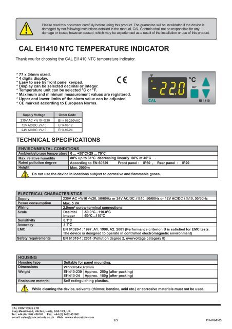
<strong>CAL</strong> <strong>EI1410</strong> NTC TEMPERATURE INDICATOR<br />
Thank you for choosing the <strong>CAL</strong> <strong>EI1410</strong> NTC temperature indicator.<br />
* 77 x 34mm sized.<br />
* 4 digits display.<br />
* Easy to use by front panel keypad.<br />
* Display can be selected decimal or integer.<br />
* Temperature unit can be selected °C or °F.<br />
* Maximum and minimum measurement values are registered.<br />
* Upper and lower limits of the alarm value can be adjusted<br />
* CE marked according to European Norms.<br />
°F<br />
<strong>CAL</strong><br />
°C<br />
SET<br />
EI 1410<br />
Supply Voltage<br />
Order Code<br />
230V AC +%10 -%20<br />
12V AC/DC ± %10<br />
<strong>EI1410</strong>-230VAC<br />
<strong>EI1410</strong>-12<br />
24V AC/DC ± %10 <strong>EI1410</strong>-24<br />
TECHNI<strong>CAL</strong> SPECIFICATIONS<br />
ENVIRONMENTAL CONDITIONS<br />
Ambient/storage temperature 0 ... +50°C/-25 ... 70°C<br />
Max. relative humidity 80% up to 31°C decreasing linearly 50% at 40°C .<br />
Rated pollution degree According to EN 60529 Front panel : IP60 , Rear panel : IP20<br />
Height<br />
Max. 2000m<br />
Do not use the device in locations subject to corrosive and flammable gases.<br />
ELECTRI<strong>CAL</strong> CHARACTERISTICS<br />
Supply<br />
Power consumption<br />
Wiring<br />
230V AC +%10 -%20, 50/60Hz or 24V AC/DC ± %10, 50/60Hz or 12V AC/DC ± %10, 50/60Hz<br />
Max. 5 VA<br />
2.5mm² screw-terminal connections<br />
Scale<br />
Decimal -50.0°C...110.0°C<br />
Integer -50°C...110°C<br />
Sensitivity<br />
Accuracy<br />
0.1°C<br />
± 1°C<br />
EMC<br />
EN 61326-1: 1997, A1: 1998, A2: 2001 (Performance criterion B is satisfied for EMC tests.<br />
The device is designed to operate in controlled electromagnetic environment)<br />
Safety requirements EN 61010-1: 2001 (Pollution degree 2, overvoltage category II)<br />
HOUSING<br />
Housing type<br />
Dimensions<br />
Weight<br />
Enclosure material<br />
Suitable for panel mounting.<br />
W77xH34xD70mm<br />
<strong>EI1410</strong>-230 Approx. 250g ( after packing)<br />
<strong>EI1410</strong>-24 Approx. 150g (after packing)<br />
Self extinguishing plastics.<br />
While cleaning the device, solvents (thinner, benzine, acid etc.) or corrosive materials must not be used.<br />
<strong>CAL</strong> CONTROLS LTD<br />
Bury Mead Road, Hitchin, Herts, SG5 1RT, UK.<br />
Tel : +44 (0) 1462 436161 Fax : +44 (0) 1462 451801<br />
e-mail: sales@cal-controls.co.uk Web : www.cal-controls.com<br />
1/3<br />
<strong>EI1410</strong>-E-<strong>03</strong>
www.cal-controls.com<br />
Input<br />
UP.l1<br />
UP.l1 - HYS<br />
LO.l1 + HYS<br />
LO.l1<br />
t<br />
Alarm<br />
t<br />
When alarm case happens, process value flashes.<br />
DIMENSIONS<br />
34mm<br />
°F<br />
<strong>CAL</strong><br />
85mm<br />
°C<br />
SET<br />
EI 1410<br />
1<br />
Flush mounting<br />
clamp<br />
Depth<br />
70mm<br />
2<br />
Panel<br />
8mm<br />
Rubber<br />
gasket<br />
For removing mounting clamps:<br />
- Push up the flush-mounting<br />
clamp in direction 1 as<br />
shown in the figure left.<br />
- Then, pull out the clamp in<br />
direction 2.<br />
R<br />
W<br />
1 2 3 4 5 6 7 8 9 10 11 12<br />
NTC<br />
SENSOR<br />
230V AC +10% -20%<br />
50/60Hz 5 VA<br />
Panel cut-out<br />
71mm<br />
Note :<br />
1) Panel thickness should be maximum 7mm.<br />
2) If there is no 60mm free space at back side of<br />
the device,it would be difficult to remove it from<br />
the panel.<br />
<strong>EI1410</strong>-230VAC<br />
NTC TEMPERATURE INDICATOR<br />
SN: XXXXXXXXX<br />
29mm<br />
Equipment is protected througout<br />
by DOUBLE INSULATION.<br />
Holding screw 0.4-0.5Nm<br />
NOTE :<br />
SUPPLY:<br />
184-253V AC<br />
50/60Hz 3VA<br />
7<br />
8<br />
Line<br />
Neutral<br />
Fuse<br />
F 100 mA<br />
250V AC<br />
Switch<br />
230V AC<br />
Supply<br />
1) Mains supply cords shall meet the requirements of<br />
IEC 60227 or IEC 60245.<br />
2) In accordance with the safety regulations, the power<br />
supply switch shall bring the identification of the relevant<br />
instrument and it should be easily accessible by the operator.<br />
Fuse should be connected.<br />
Cable size: 1,5mm²<br />
CONNECTION DIAGRAM<br />
<strong>CAL</strong> <strong>EI1410</strong> is intended for installation in control panels. Make sure that the device is used only for<br />
intended purpose. The shielding must be grounded on the instrument side. During an installation, all<br />
of the cables that are connected to the device must be free of electrýcal power. The device must be<br />
protected against inadmissible humidity, vibrations, severe soiling and make sure that the operation<br />
temperature is not exceeded. All input and output lines that are not connected to the supply network<br />
must be laid out as shielded and twisted cables. These cables should not be close to the power<br />
cables or components. The installation and electrical connections must be carried out by qualified<br />
staff and must be according to the relevant locally applicable regulations.<br />
www.cal-controls.com<br />
<strong>EI1410</strong>-230VAC<br />
NTC TEMPERATURE INDICATOR<br />
SN: XXXXXXXXX<br />
www.cal-controls.com<br />
<strong>EI1410</strong>-24<br />
NTC TEMPERATURE INDICATOR<br />
SN: XXXXXXXXX<br />
230V AC +10% -20%<br />
50/60Hz 5 VA<br />
NTC<br />
SENSOR<br />
24V AC/DC 10%<br />
50/60Hz 5VA<br />
NTC<br />
SENSOR<br />
W R<br />
1 2 3 4 5 6 7 8 9 10 11 12<br />
W R<br />
1 2 3 4 5 6 7 8 9 10 11 12<br />
2/3<br />
<strong>EI1410</strong>-E-<strong>03</strong>
<strong>EI1410</strong> PROGRAMMING DIAGRAM<br />
°F<br />
°C<br />
SET<br />
Increment<br />
key<br />
Decrement<br />
key<br />
Used for changing parameters and increasing the setpoint value. When held down for a<br />
few seconds, the change rate accelerates.<br />
Used for changing parameters and decreasing the setpoint value. When held down for a<br />
few seconds, the change rate accelerates.<br />
ENDA<br />
EI 1410<br />
Programming<br />
key<br />
SET<br />
Used for displaying value of the selected parameter and adjusting the selected<br />
parameter.<br />
RUN MODE<br />
SET<br />
While holding key, measured maximum temperature value appears.<br />
When the device is first enerjised or by pressing key, while holding key,<br />
SET<br />
Process value<br />
measured maximum temperature value is made equal to process temperature value.<br />
SET<br />
While holding key, measured minimum temperature value appears.<br />
When the device is first enerjised or by pressing key, while holding key,<br />
SET<br />
measured minimum temperature value is made equal to process temperature value.<br />
If both & keys are pressed and held for 3 seconds, programming mode is entered or run mode is returned.<br />
PROGRAMMING MODE<br />
SET<br />
If this key is pressed,<br />
upper limit value<br />
appears.<br />
SET<br />
If this key is pressed,<br />
lower limit value<br />
appears.<br />
SET<br />
Upper limit<br />
value<br />
Lower limit<br />
value<br />
Hysteresis<br />
value<br />
SET<br />
By using and keys, while holding key, the upper limit can be adjusted to desired value<br />
between -50.0°C and 110.0°C . Minimum value of this parameter must be ( lo.l1 + 2 * HYS ).<br />
SET<br />
By using and keys, while holding key, the lower limit can be adjusted to desired value<br />
between -50.0°C and 110.0°C. Maximum value of this parameter must be ( Up.l1 - 2 * HYS ).<br />
SET<br />
By using and keys, while holding key, hysteresis value can be adjusted to desired value<br />
If this key is pressed,<br />
hysteresis value<br />
appears.<br />
SET<br />
Offset<br />
value<br />
between 0.0°C and 10.0°C. Maximum value of this parameter must be ( Up.l1 - Lo.l1 ) / 2.<br />
SET<br />
By using and keys, while holding key, offset can be adjusted to desired value<br />
If this key is pressed,<br />
offset value<br />
appears.<br />
SET<br />
Display<br />
resolution<br />
If this key is pressed,<br />
display alternatives<br />
appears.<br />
Temperature<br />
SET<br />
unit<br />
between 0 .0°C ile 20.0°C.<br />
SET<br />
By using and keys, while holding key, display can be selected decimal or integer.<br />
When Yes is selected, decimal case is entered. If no is selected, integer case is entered.<br />
All of other parameters are adjusted according to selection.<br />
SET<br />
By using and keys, while holding key, temperature unit can be selected °C or °F.<br />
If this key is pressed,<br />
temperature unit<br />
appears.<br />
If no key is pressed within 20 seconds, the device will time out back to the run mode. Alternatively, re-energising the device, run mode is entered.<br />
ERROR MESSAGES<br />
Means, thermostat probe is short circuit or temperature value is higher than the scale.<br />
Means, thermostat probe is broken or temperature value is lower than the scale.<br />
3/3<br />
<strong>EI1410</strong>-E-<strong>03</strong>


