

Next Generation: GSR Guardmaster Safety Relays - OEM Automatic ...
Next Generation: GSR Guardmaster Safety Relays - OEM Automatic ...
Next Generation: GSR Guardmaster Safety Relays - OEM Automatic ...

Create successful ePaper yourself
Turn your PDF publications into a flip-book with our unique Google optimized e-Paper software.
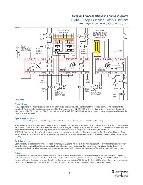
Safeguarding Applications and Wiring Diagrams<br />
Global E-Stop, Cascaded <strong>Safety</strong> Functions<br />
800F, Trojan T15, MatGuard, SI, DI, DIS, 100S, 700S<br />
+24V DC<br />
K1<br />
K2<br />
Start<br />
Trojan T15-GD2<br />
440K-T11397<br />
Start<br />
K3<br />
K4<br />
MatGuard<br />
<strong>Safety</strong> Mat & Trim<br />
440F-M2030BYNN<br />
440F-T2030<br />
K5<br />
K6<br />
E-Stop<br />
800FM-MT44<br />
800F-MX02S<br />
Reset<br />
800FM-<br />
F6MX10<br />
Stop<br />
11 12<br />
21 22<br />
11 12<br />
21 22<br />
Stop<br />
Reset<br />
800FM-<br />
F6MX10<br />
Aux. to PLC<br />
S11 S12<br />
A1 S34 13<br />
23<br />
S11<br />
S12 S21 S22<br />
A1<br />
13<br />
23<br />
S34<br />
S11 S21 S12 S22<br />
A1<br />
A2<br />
Y32 S34<br />
RESET 0<br />
AM<br />
SI<br />
MM<br />
440R-S12R2<br />
S21 S22 A2 L11 Y32 14<br />
24<br />
LOGIC<br />
8<br />
7<br />
DI<br />
440R-D22R2<br />
6<br />
0 1<br />
2<br />
3<br />
4<br />
5<br />
S32 S42 L11 L12 A2 14 24 Y32<br />
LOGIC<br />
8<br />
7<br />
DIS<br />
440R-D22S2<br />
6<br />
0 1<br />
2<br />
3<br />
4<br />
5<br />
S32 S42 L11 L12 34 44 14 24<br />
Aux.<br />
to PLC<br />
100S or<br />
700S<br />
K1 K2 K3 K4<br />
E-Stop<br />
800FM-MT44<br />
800F-MX02S<br />
Aux.<br />
to PLC<br />
100S or<br />
700S<br />
E-Stop<br />
800FM-MT44<br />
800F-MX02S<br />
K5<br />
K6<br />
Start<br />
Stop<br />
100S or<br />
700S<br />
K5<br />
K6<br />
K5<br />
K6<br />
24 DC Com<br />
Circuit Status<br />
The E-Stops are reset. The safety gate is closed. The safety mat is unoccupied. The outputs of all three controls are off. K1-K6 are ready to be<br />
energized. The SI is set for monitored manual reset. The DI has logic set to 4 [(IN1 AND IN2) AND L12] with monitored manual reset because the<br />
safet gate provides full body access. The DIS has logic set to 8 [(IN1AND IN2) AND L12] with automatic reset as operators cannot get between the<br />
safety mat and the hazard.<br />
Operating Principle<br />
The SI is connected to provide a Global E-Stop function. The DI and DIS safety relays are cascaded from the SI relay.<br />
STARTING: Press the reset button for the SI to energize its outputs. Then press the Start button energize K1 and K2 and send the L11 link signal to<br />
the DI Relay. This enables the DI relay. Press the reset button to energize to energize the DI relay. This sends a L11 link signal to the DIS relay. The<br />
outputs of the DIS energize automatically. Press the respective Start buttons to energize the contactors K3, K4, K5 and K6.<br />
STOPPING: Pressing the E-Stop of the SI shuts down all three relays. Opening the interlocked gate or pressing the E-Stop of the DI turns off the<br />
outputs of both the DI and DIS, while the SI is unaffected. Pressing the E-Stop or stepping on the safety mat of the DIS turns off the outputs of the<br />
DIS only.<br />
Fault Detection<br />
Upon successful completion of internal checks on power up, the SI, DI and DIS relays check their input circuits. Shorts from the inputs to power,<br />
ground or other inputs will be detected immediately and will prevent energization or will de-energize the respective outputs. If one of the<br />
contactors (K1 - K6) is stuck in an actuated state, the respective control will prevent startup because the S34 feedback loop will remain open.<br />
Ratings<br />
The safety functions initiated by the e-stop devices and the two Trojan interlocks meet the safety performance requirements of SIL CL3 per IEC<br />
62061:2005 and have Category 4 structures that can be used in systems requiring Performance Levels up to PLe per ISO13849-1:2008. The safety<br />
function initiated by the safety mat meets the safety performance requirements of SIL CL2 per IEC 62061:2005 and has a Category 3 structure that<br />
can be used in systems requiring Performance Levels up to PLd per ISO13849-1:2008. This circuit executes a Category 0 stop.<br />
- 6 -<br />
R


