SAMBA3G-E LVD Report - Falcom
SAMBA3G-E LVD Report - Falcom
SAMBA3G-E LVD Report - Falcom

You also want an ePaper? Increase the reach of your titles
YUMPU automatically turns print PDFs into web optimized ePapers that Google loves.
EUROFINS ETS PRODUCT SERVICE GMBH<br />
TEST - REPORT<br />
EN 60950-1:2006<br />
TEST REPORT NUMBER: G0M20807-1884-L<br />
Eurofins ETS Product Service GmbH<br />
Storkower Str. 38c, 15526 Reichenwalde, Phone +49-33631-888 0<br />
Germany Fax +49-33631-888 660
Table of contents<br />
1. General Information 2<br />
1.1. Notes 2<br />
1.2. Operator 3<br />
1.3. Testing laboratory 4<br />
1.4. Application details 4<br />
1.5. Test item 5<br />
1.6. Test standards 6<br />
2. Technical test 7<br />
2.1. Summary of test results 7<br />
2.2. Test environment 7<br />
2.3. Test equipment utilised 8<br />
2.4. List of non-conformance items and general recommendations 12<br />
3. Test Results 13<br />
3.1. Particulars: Test item vs. Test requirements 13<br />
3.2. Tables 50<br />
3.3. Alternative components 57<br />
3.4. Diagrams 58<br />
4. Documentation 59<br />
4.1. Pictures 59<br />
4.2. Essentials of Product Documentation 61<br />
5. Appendix of test <strong>Report</strong> 62<br />
5.1. Enclosure PAH 62<br />
5.2. Enclosure ITB 2000 63<br />
Test <strong>Report</strong> No.: G0M20807-1884-L<br />
Eurofins ETS Product Service GmbH<br />
Storkower Str. 38c, D-15526 Reichenwalde, Germany<br />
Page 1 of 63
1. General Information<br />
1.1. Notes<br />
The purpose of conformity testing is to increase the probability of adherence to the essential requirements or<br />
conformity specifications, as appropriate.<br />
The complexity of the technical specifications, however, means that full and thorough testing is impractical<br />
for both technical and economic reasons.<br />
Furthermore, there is no guarantee that a test sample which has passed all the relevant tests conforms to a<br />
specification (only telecommunication products).<br />
Neither is there any guarantee that such a test sample will interwork with other genuinely open systems.<br />
The existence of the tests nevertheless provides the confidence that the test sample possesses the qualities<br />
as maintained and that its performance generally conforms to representative cases of communications<br />
equipment.<br />
The test results of this test report relate exclusively to the item tested as specified in 1.5.<br />
The test report may only be reproduced or published in full.<br />
Reproduction or publication of extracts from the report requires the prior written approval of the<br />
EUROFINS ETS PRODUCT SERVICE GMBH<br />
Test <strong>Report</strong> No.: G0M20807-1884-L<br />
Eurofins ETS Product Service GmbH<br />
Storkower Str. 38c, D-15526 Reichenwalde, Germany<br />
Page 2 of 63
1.3. Testing laboratory<br />
1.3.1. Location<br />
EUROFINS ETS PRODUCT SERVICE GMBH<br />
Storkower Str. 38 c<br />
D- 15526 Reichenwalde<br />
Germany<br />
Telephone : + 49 33631 888-00<br />
Telefax : + 49 33631 888-660<br />
1.3.2. Test location, where different:<br />
Name : ./.<br />
Street : ./.<br />
Town : ./.<br />
Country : ./.<br />
Telephone : ./.<br />
Fax : ./.<br />
1.4. Application details<br />
1.4.1. Details of applicant<br />
Name : <strong>Falcom</strong> Wireless Communications GmbH<br />
Street : Gewerbering 6,<br />
Town : 98704 Langewiesen,<br />
Country : Germany<br />
Telephone : +49(0)3677 8042-0<br />
Fax : +49(0)3677 8042-215<br />
Contact : Mr. Ralf Leipoldt<br />
Telephone : +49(0)3677 8042-0<br />
Test <strong>Report</strong> No.: G0M20807-1884-L<br />
Eurofins ETS Product Service GmbH<br />
Storkower Str. 38c, D-15526 Reichenwalde, Germany<br />
Page 4 of 63
1.4.2. Details of wanted approval holder<br />
Name : <strong>Falcom</strong> Wireless Communications GmbH,<br />
Street : Gewerbering 6,<br />
Town : 98704 Langewiesen,<br />
Country : Germany<br />
Telephone : +49(0)3677 8042-0<br />
Fax : +49(0)3677 8042-215<br />
Contact : Mr. Ralf Leipoldt<br />
Telephone : +49(0)3677 8042-0<br />
1.4.3. Manufacturer<br />
Name : <strong>Falcom</strong> Wireless Communications GmbH<br />
Street : Gewerbering 6<br />
Town : 98704 Langewiesen<br />
Country : Germany<br />
1.4.4. Dates of application<br />
Date of receipt of application : 08.07.2008<br />
Date of receipt of test item : 08.07.2008<br />
Date of test : 08.07.2008 up to 18.09.2008<br />
1.5. Test item<br />
1.5.1. Description of test item<br />
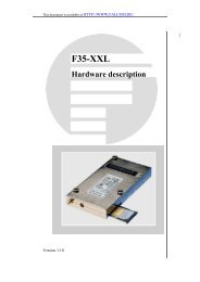
Description of test item : GSM/UMTS-Stick<br />
Type identification : <strong>SAMBA3G</strong>-E<br />
Brand Name :<br />
Serial number : without<br />
Number of samples : 2<br />
Test <strong>Report</strong> No.: G0M20807-1884-L<br />
Eurofins ETS Product Service GmbH<br />
Storkower Str. 38c, D-15526 Reichenwalde, Germany<br />
Page 5 of 63
1.5.2. Technical data<br />
Test item .........................................: GSM/UMTS-Stick (data modem)<br />
Protection class ..............................: class III<br />
Add. Mark. ......................................: CE0681, EN 50419<br />
Rated Power ...................................: USB (5V,
2. Technical test<br />
2.1. Summary of test results<br />
No deviations from the technical specification(s) were ascertained in the course<br />
of the tests performed.<br />
Or<br />
The deviations as specified in 2.4 were ascertained in the course of the tests<br />
performed.<br />
2.2. Test environment<br />
Temperature : -20 to 75 °C ± 1K<br />
Relative humidity content : 46 %<br />
Air pressure : 1007 hPa ± 10 hPa<br />
Altitude of test location : 57 m above NN<br />
Details of power supply : ETS 0186 (0-70V; 0-20A)<br />
Other parameters:<br />
Test <strong>Report</strong> No.: G0M20807-1884-L<br />
Eurofins ETS Product Service GmbH<br />
Storkower Str. 38c, D-15526 Reichenwalde, Germany<br />
Page 7 of 63
2.3. Test equipment utilised<br />
ID No. Test equipment Type Manufacturer<br />
ETS 0046 Separation transformer LTS 006 RFT<br />
ETS 0160 Protective wire and isolation tester PI 6001 D SPS electronic<br />
ETS 0186 Power supply LD75/20 GD-1 Zentro-Elektrik<br />
ETS 0195 Thermo hygro recorder C 042801 Amarell<br />
ETS 0205 High voltage test generator HA 3300 D SPS electronic<br />
ETS 0206 Leakage current tester AI5010D SPS electronic<br />
ETS 0208 Unjointed Finger probe P 10.05 PTL (Sonde 11)<br />
ETS 0209 Flexible Finger probe (EN 60950) P 10.01 PTL (Sonde B)<br />
ETS 0210 Flexible Finger probe - modified EN 60335-2-14 ETS<br />
ETS 0211 Metallic ball 50mm Isometall<br />
ETS 0213<br />
Hazardous live probe 3mm (EN<br />
P 10.11 PTL (Sonde 13)<br />
60950)<br />
ETS 0214 Ball pressure test apparatus T 10.02 PTL<br />
ETS 0215 Glow Wire tester T 03.14 PTL<br />
ETS 0216 Force gauge 50N P 10.31 PTL<br />
ETS 0217 Force gauge 500N FMI-100BU Alluris GmbH<br />
ETS 0312 Climatic chamber VC0033 Heraeus Vötsch<br />
ETS 3001 Termal Imager Ti20 Fluke<br />
ETS 3002 Bunsen burner H-6241N ED&D<br />
ETS 3003 Needle flame burner Needle flame ETS / CFH<br />
ETS 3004 Digital Caliper 10-871-2 ED&D<br />
ETS 3005 Digital Caliper 10-871-2 ED&D<br />
ETS 3006 Digital Caliper AD-300 Hogetex<br />
ETS 3007 Feeler Gauges (EN 61032) Sonde A LGA / ETS /<br />
Sonde C Schneider / Sunho<br />
Sonde D<br />
Sonde 1<br />
Sonde 2<br />
Sonde 11<br />
Sonde 12<br />
Sonde 13<br />
Sonde 14<br />
Sonde 17<br />
Sonde 18<br />
Sonde 19<br />
Sonde 31<br />
Sonde 32<br />
Sonde 41<br />
Sonde 43<br />
Sonde 60950-1<br />
Sonde 60335-2-14<br />
Sonde 60598-2-20<br />
ETS 3008 Go gauge and No go gauge set ETS<br />
ETS 3009 Heating oven UT 6120 Heraeus Instr.<br />
ETS 3010 Inclined plane (10°) --- ETS<br />
ETS 3011 Digital Caliper AD-300 Hogetex<br />
ETS 3012 Insulation tester SAIT20 Summit<br />
ETS 3013 Separation / variable transformer LTS 606<br />
Test <strong>Report</strong> No.: G0M20807-1884-L<br />
Eurofins ETS Product Service GmbH<br />
Storkower Str. 38c, D-15526 Reichenwalde, Germany<br />
Thalheimer<br />
Transformator-werke<br />
Page 8 of 63
ID No. Test equipment Type Manufacturer<br />
ETS 3014 Laser test system<br />
LabMaster / LM2 /<br />
LM10<br />
Coherent<br />
ETS 3015<br />
8-channel thermocouple input<br />
module<br />
ADAM-4018-D2 Advantech<br />
ETS 3016<br />
8-channel thermocouple input<br />
module<br />
ADAM-4018-D2 Advantech<br />
ETS 3017 Optical comperator 20x Hensoldt-Wetzlar<br />
ETS 3018 Optical comperator 40x Hensoldt-Wetzlar<br />
ETS 3019 Optical comperator 8x Hensoldt-Wetzlar<br />
ETS 3020 Transformer 5358.61 Statron<br />
ETS 3021 Transformer 5358.61 Statron<br />
ETS 3022 Transformer 5358.61 Statron<br />
ETS 3025 Spectrum Analyzer 3588A HP<br />
ETS 3026 Impact test apparatus EN 60598-2-5 Schütz<br />
ETS 3027 Crush test apparatus EN 60598-2-8 Schütz<br />
ETS 3028 Feeler probe (6x0,4mm) EN 71-1 13 ETS Product Service<br />
ETS 3029 Turning moment tester ETS Product Service<br />
ETS 3030 Torque spanner No. 4550-00 Rahsol<br />
ETS 3031 Screwdriver with adjustable torque No. 758 Rahsol<br />
ETS 3033 Weights set 1g-1000g Fritzsche-Dolgner<br />
Weight 1000g Fritzsche-Dolgner<br />
Weight 2000g Fritzsche-Dolgner<br />
ETS 3034 Digital thermometer VC 502 Voltcraft<br />
ETS 3037 Light meter CHY 331 Conrad Kfc<br />
ETS 3038 Digital photo tachometer DT-2234B-A JTW<br />
ETS 3040 Digital multimeter YH-3900 Digitek<br />
ETS 3041 Digital multimeter DT-6700 Huapu<br />
ETS 3042 Electronic Load EL 7000 ELV<br />
ETS 3043 High voltage tester DC (AC) SIP 010 RFT<br />
ETS 3044<br />
Precision multifunctional measuring<br />
device<br />
Testo 445 TESTO<br />
Co Sensor TESTO<br />
ETS 3046 Digital Oscilloskop TDS 520A Tektronix<br />
Probe A (ETS 3046a) Tektronix<br />
Probe B (ETS 3046b) Tektronix<br />
ETS 3052 Digital multimeter UT 30B-L UNI-T<br />
ETS 3053 Infrared Thermometer AZ AZ Instruments<br />
ETS 3055 Digital multimeter ET-2092 Minipa<br />
ETS 3056 Digital multimeter Fluke-189 Fluke<br />
ETS 3057 Digital multimeter Fluke-189 Fluke<br />
ETS 3058 Sound level meter (50 - 100dBA) 33-2055 Radio shack<br />
ETS 3059 Sound level meter (30 - 130dBA) 8921 AZ Instruments<br />
ETS 3060 Sound level meter CR:811B Cirrus Research<br />
ETS 3061 Acoustic calibrator CR:511E Cirrus Research<br />
ETS 3063<br />
Apparatus for testing the durability<br />
of markings<br />
EN 60730 ETS Germany<br />
ETS 3066 Plug Bending Tester JDW-1R<br />
GZ ZhiLiTong<br />
Electromech.<br />
ETS 3069 Dosimeter 6150 AD 5/E automess<br />
ETS 3070 Pendulum hammer test apparatus IEC 60068-2-75 LGA<br />
ETS 3071 Creepage distance test apparatus SH5201 Sunho<br />
ETS 3072 Scratch test apparatus --- ETS Germany<br />
Test <strong>Report</strong> No.: G0M20807-1884-L<br />
Eurofins ETS Product Service GmbH<br />
Storkower Str. 38c, D-15526 Reichenwalde, Germany<br />
Page 9 of 63
ID No. Test equipment Type<br />
EN 60730 Fig3 EN<br />
Manufacturer<br />
ETS 3074 Test Fingernail<br />
60335 Fig7 EN<br />
60745 Fig7<br />
EST China<br />
ETS 3075<br />
Pressure plate (250N up to 800N)<br />
Ø30mm<br />
EN 60950-1 cl.4.1<br />
ETS 3076<br />
Test hook (180mm by 5mm by<br />
8mm)<br />
EN 60065-1 Fig4; EN<br />
ETS Germany<br />
71-1 8.8<br />
ETS 3078<br />
Test plug for mechanical tests on<br />
coaxial junctions<br />
EN 60065 Fig9 ETS Germany<br />
ETS 3079 Impact block Ø80mm, 1kg EN 71-1 8.7 Schütz<br />
ETS 3080 Test wire set [Ø1,0mm / Ø0,5mm)<br />
EN 60335-2-25<br />
EN 62115<br />
ETS Germany<br />
ETS 3082 Tumbling barrel GT-1<br />
GZ ZhiLiTong<br />
Electromech.<br />
ETS 3083<br />
Measuring device for ultrasonic<br />
sound pressure<br />
ETS 3085 Biological Microscope Lab00x<br />
GZ Optical<br />
Instrumental Factory<br />
ETS 3086 Test chain for lamps IEC 60598<br />
P310 P310<br />
Friborg<br />
ETS 3087<br />
Standard resistance set (1m� P321 P321<br />
- 100000�)<br />
P321 P331<br />
P331 P331<br />
UdSSR<br />
ETS 3089 Stop watch JS-6000 JUNSO<br />
ETS 3090 Electric balance PSC-12 UWE<br />
ETS 3091 Electric balance SI-1 ACOM<br />
ETS 3095<br />
Dimension measurement standard<br />
(25mm)<br />
--- Westfalia<br />
ETS 3097<br />
Precision multifunction measuring<br />
device<br />
testo 650 TESTO<br />
Temperature surface sensor --- TESTO<br />
Highly accurate<br />
humidity/temperature probe<br />
--- TESTO<br />
Pressure probe 2bar --- TESTO<br />
Rotational speed measuring probe --- TESTO<br />
ETS 3102 UV-Meter RM-21<br />
Dr.Gröbel UV-<br />
Elektronik GmbH<br />
UV-A Sensor UVA<br />
Dr.Gröbel UV-<br />
Elektronik GmbH<br />
UV-B Sensor UVB<br />
Dr.Gröbel UV-<br />
Elektronik GmbH<br />
UV-C Sensor UVC<br />
Dr.Gröbel UV-<br />
Elektronik GmbH<br />
Brightness Sensor Lux<br />
Dr.Gröbel UV-<br />
Elektronik GmbH<br />
ETS 3151 Digital Multimeter M840D UNI-T<br />
ETS 3153 High voltage probe P6015 P6016 Tektronix<br />
ETS 3154 Vibration table N1-201-M Sandox<br />
ETS 3155 Socket-Outlet torque balance F 37.13 PTL<br />
ETS 3156 Spring operated impact hammer P 22.50 PTL<br />
ETS 3157 Power harmonics analyzer Fluke-41B Fluke<br />
ETS 3158 AC-clamp 500 A 80i 500s Fluke<br />
ETS 3159 AC-clamp 1000 A 80i 1000s Fluke<br />
Test <strong>Report</strong> No.: G0M20807-1884-L<br />
Eurofins ETS Product Service GmbH<br />
Storkower Str. 38c, D-15526 Reichenwalde, Germany<br />
Page 10 of 63
ID No. Test equipment Type Manufacturer<br />
ETS 3161 Dust Chamber SC-500 DongZhi Xu<br />
ETS 3167 Small parts cylinder EN 71 fig12 ETS Product Service<br />
ETS 3168 Climatic chamber VT4010 Heraeus Vötsch<br />
ETS 3169 Drip device for IPX1 / IPX2 SH8102 Sunho<br />
ETS 3170 Testing apparatus for IPX3 / IPX4 SH8101B Sunho<br />
ETS 3171 Rain test apparatus for IPX5 / IPX6 SH8105 Sunho<br />
ETS 3175 Measuring circuit for touch current<br />
IEC 60990 fig4<br />
ETS Product Service<br />
IEC/EN 60950-1<br />
ETS 3180 Test generator (120V) EN 60950 EuroEMC<br />
ETS 3181 AC Source 40Hz - 3kHz, 1000W ETS<br />
ETS 3183 Power source DPS-300GL Loko<br />
ETS 3184 Voltage regulator TND3-1000VA<br />
Dianxing Electr.<br />
Test <strong>Report</strong> No.: G0M20807-1884-L<br />
Eurofins ETS Product Service GmbH<br />
Storkower Str. 38c, D-15526 Reichenwalde, Germany<br />
Appliance<br />
ETS 3185 Laser level LS165<br />
Laisai Laser<br />
Engineering<br />
ETS 3187 DC Source (rectifier) 10V 40A RFT<br />
ETS 3188<br />
Sharp cusp test instrument (EN 71<br />
Fig16)<br />
TNC28 Tonny Instrument<br />
ETS 3189<br />
Sharp edge test instrument (EN 71<br />
TNC27 Tonny Instrument<br />
Fig15)<br />
ETS 3190 Test template A (EN 71 Fig17) TNC31A (oval) Tonny Instrument<br />
ETS 3191 Test template B (EN 71 Fig18) TNC31B (round) Tonny Instrument<br />
ETS 3192 Electronic Load 3223.1 Statron<br />
ETS 3193 AC Source (250A) 5902 LGA<br />
ETS 3194 Glow Wire tester GTR-B<br />
GZ ZhiLiTong<br />
Electromech.<br />
ETS 3195 Digital Caliper 10-871-2 ED&D<br />
ETS 3196 Digital Caliper 10-871-2 ED&D<br />
ETS 3197 Lamp chain test apparatus EN 60598-2-20 fig2 ETS<br />
ETS 3198 Lamp gauges E14<br />
(C) Normal, Contactmaking<br />
(Z) Not Go<br />
(F) protection against<br />
accidental contact<br />
(ZC) Candle shaped<br />
(T) Go<br />
GZ SZ Testing<br />
Technology<br />
ETS 3199 Lamp gauges E27 (T) Go<br />
(Z) No Go<br />
(R) Detecting<br />
contacts<br />
(F) Protection against<br />
accidental contact<br />
(C) Protection<br />
against bulb-neck<br />
damage<br />
(H1) Gauge I for<br />
checking contact<br />
resiliency<br />
(H2) Gauge II for<br />
checking contact<br />
resiliency<br />
GZ SZ Testing<br />
Technology<br />
Page 11 of 63
2.4. List of non-conformance items and general recommendations<br />
Non-conformance items<br />
GSM/UMTS-Stick <strong>SAMBA3G</strong>-E<br />
No. Clause Non-conformance details Recommended corrective action<br />
No non-conformance details noticed<br />
- over -<br />
Test <strong>Report</strong> No.: G0M20807-1884-L<br />
Eurofins ETS Product Service GmbH<br />
Storkower Str. 38c, D-15526 Reichenwalde, Germany<br />
Page 12 of 63
3. Test Results<br />
3.1. Particulars: Test item vs. Test requirements<br />
Test item particulars ...................................................:<br />
EN 60950-1<br />
Information technology and office equipment<br />
Equipment mobility.................................................... : [x] movable [] hand-held [] transportable<br />
[] stationary [] for building-in [x] direct plug-in<br />
Connection to the mains ........................................... : [x] *1 pluggable equipment [] permanent connection<br />
[] *1 detachable power supply cord (Rx)<br />
[] non-detachable power supply cord<br />
[x] not directly connected to the mains<br />
Operating condition................................................... : [x] continuous<br />
[] rated operating / resting time:<br />
Over voltage category (OVC) ................................... : [] OVC I [] OVC II [] OVC III [] OVC IV<br />
Mains supply tolerance (%)....................................... : 4,75V-5,25V d. c.<br />
Tested for IT power systems .................................... : [] *1 Yes [x] No<br />
IT testing, phase-phase voltage (V) ......................... : -<br />
Class of equipment .................................................. : [] Class I [] Class II [x] Class III [] Not classified<br />
Pollution degree (PD) ............................................... : [] PD 1 [x] PD 2 [] PD 3<br />
IP protection class .................................................... : IP X0<br />
Altitude during operation (m) .................................... : � 2000m * 2<br />
Altitude of test laboratory (m) ................................... : 57m<br />
Mass of equipment (kg) ............................................ : 35g, LxBxH=88,7x37,6x14,1mm<br />
Possible test case verdicts:<br />
- test case does not apply to the test object.................: N/A<br />
- test object does meet the requirement.......................: P (Pass)<br />
- test object does not meet the requirement.................: F (Fail)<br />
*1 USB connector<br />
* 2 correction factor = 1,0 apply (table A.2 EN 60664-1:2007)<br />
"(See Enclosure #)" refers to additional information appended to the report.<br />
"(See appended table)" refers to a table appended to the report.<br />
Test <strong>Report</strong> No.: G0M20807-1884-L<br />
Eurofins ETS Product Service GmbH<br />
Storkower Str. 38c, D-15526 Reichenwalde, Germany<br />
Page 13 of 63
General product information:<br />
The product represents a GSM/UMTS-Stick (data modem). The product will powered by USB interface.<br />
This test report refers to the tested specimen(s) only.<br />
The product represents a prototype. Some markings (without influence at safety) must be considered for<br />
the end product.<br />
The tested specimen complies with the requirements of EN 60950-1:2006.<br />
The evidence of RoHS conformity has been presented. Corresponding documents are available.<br />
Abbreviations :<br />
L, N, PE = Line, neutral, protective earth<br />
EUT = Equipment under Test<br />
PCB = Printed circuit (wiring) board<br />
F, B, S, R, D = Functional-, Basic-, Supplementary-, Reinforced-, and Double Insulation<br />
SELV = safety extra low voltage<br />
LPS = Limited Power Source (EN 60950-1:2006 clause 2.5)<br />
USB = Universal Serial Bus<br />
Copy of the product label<br />
(see also 4.1 Documentation/Pictures)<br />
Test <strong>Report</strong> No.: G0M20807-1884-L<br />
Eurofins ETS Product Service GmbH<br />
Storkower Str. 38c, D-15526 Reichenwalde, Germany<br />
Page 14 of 63
IEC 60950-1 / EN 60950-1<br />
Clause Requirement - Test Result - Remark Verdict<br />
1 GENERAL<br />
1.5 Components<br />
1.5.1 General<br />
Comply with IEC 60950 or relevant component<br />
standard<br />
Test <strong>Report</strong> No.: G0M20807-1884-L<br />
Eurofins ETS Product Service GmbH<br />
Storkower Str. 38c, D-15526 Reichenwalde, Germany<br />
Components comply with the<br />
requirements of this standard or<br />
with relevant IEC component<br />
standards.<br />
(see appended table 1.5.1)<br />
1.5.2 Evaluation and testing of components Components used within its<br />
ratings<br />
1.5.3 Thermal controls No such components N/A<br />
1.5.4 Transformers No such components N/A<br />
1.5.5 Interconnecting cables No such components N/A<br />
1.5.6 Capacitors bridging insulation Product represents a secondary<br />
circuit without dangerous<br />
voltages (SELV)<br />
1.5.7 Resistors bridging insulation<br />
1.5.7.1 Resistors bridging functional, basic or<br />
supplementary insulation<br />
1.5.7.2 Resistors bridging double or reinforced insulation<br />
between a.c. mains and other circuits<br />
1.5.7.3 Resistors bridging double or reinforced insulation<br />
between a.c. mains and antenna or coaxial cable<br />
As far applied, for functional<br />
insulation; see 2.10.3/4 and 2.4<br />
P<br />
P<br />
N/A<br />
No such parts N/A<br />
No such parts N/A<br />
1.5.7.4 Accessible parts class III product N/A<br />
1.5.8 Components in equipment for IT power systems N/A<br />
1.5.9 Surge suppressors P<br />
1.5.9.1 General Application in secondary circuit P<br />
1.5.9.2 Protection of VDRs Test result in table 5.3 P<br />
1.5.9.3 Bridging of functional insulation by a VDR P<br />
1.5.9.4 Bridging of basic insulation by a VDR N/A<br />
1.5.9.5 Bridging of supplementary, double or reinforced<br />
insulation by a VDR<br />
P<br />
N/A<br />
Page 15 of 63
IEC 60950-1 / EN 60950-1<br />
Clause Requirement - Test Result - Remark Verdict<br />
1.6 Power interface<br />
1.6.1 AC power distribution systems Appliance without connection to<br />
an AC mains supply<br />
1.6.2 Input current (see appended table 1.6) P<br />
1.6.3 Voltage limit of hand-held equipment � 250V P<br />
1.6.4 Neutral conductor N/A<br />
1.7 Marking and instructions<br />
1.7.1 Power rating Product without direct<br />
N/A<br />
Rated voltage(s) or voltage range(s) (V) ............:<br />
connection to a mains supply<br />
N/A<br />
Symbol for nature of supply, for d.c. only ........... : N/A<br />
Rated frequency or rated frequency range (Hz) . : N/A<br />
Rated current (mA or A)...................................... :<br />
Manufacturer’s name or trademark or<br />
identification mark ............................................... :<br />
Test <strong>Report</strong> No.: G0M20807-1884-L<br />
Eurofins ETS Product Service GmbH<br />
Storkower Str. 38c, D-15526 Reichenwalde, Germany<br />
<strong>Falcom</strong> Wireless<br />
Communications GmbH<br />
Type / model or type reference...........................: <strong>SAMBA3G</strong>-E P<br />
Symbol for Class II equipment only ....................: N/A<br />
Other symbols .....................................................: CE0681, EN 50419<br />
P<br />
Certification marks ..............................................:<br />
P<br />
1.7.2 Safety instructions and markings P<br />
1.7.2.1 General User instructions present P<br />
1.7.2.2 Disconnect devices Disconnection devices on the<br />
appliance<br />
N/A<br />
1.7.2.3 Overcurrent protective device No pluggable equipment type B,<br />
No permanently connected equ.<br />
1.7.2.4 IT power distribution systems N/A<br />
1.7.2.5 Operator access with a tool No N/A<br />
1.2.7.6 Ozone N/A<br />
1.7.3 Short duty cycles No restrictions for operation time N/A<br />
1.7.4 Supply voltage adjustment..................................: No voltage adjustment N/A<br />
Methods and means of adjustment; reference to<br />
installation instructions........................................:<br />
1.7.5 Power outlets on the equipment .........................: No power outlet N/A<br />
1.7.6 Fuse identification (marking, special fusing<br />
characteristics, cross-reference).........................:<br />
N/A<br />
N/A<br />
P<br />
N/A<br />
N/A<br />
appliance without fuse N/A<br />
Page 16 of 63
IEC 60950-1 / EN 60950-1<br />
Clause Requirement - Test Result - Remark Verdict<br />
1.7.7 Wiring terminals Product without wiring terminals<br />
1.7.7.1 Protective earthing and bonding terminals .........: N/A<br />
1.7.7.2 Terminal for a.c. mains supply conductors N/A<br />
1.7.7.3 Terminals for d.c. mains supply conductors N/A<br />
1.7.8 Controls and indicators<br />
1.7.8.1 Identification, location and marking.....................: Controls and Indicators without N/A<br />
1.7.8.2 Colours................................................................:<br />
influence at appliance’s safety<br />
N/A<br />
1.7.8.3 Symbols according to IEC 60417........................: N/A<br />
1.7.8.4 Markings using figures ........................................:<br />
N/A<br />
1.7.9 Isolation of multiple power sources.....................: N/A<br />
1.7.10 Thermostats and other regulating devices - No devices which are to be to<br />
adjust by installation<br />
1.7.11 Durability Must be considered for the end<br />
product (see General Product<br />
Information)<br />
1.7.12 Removable parts ................................................: Markings not at removable parts N/A<br />
1.7.13 Replaceable batteries ......................................... : appliance without battery<br />
P<br />
Language(s) ........................................................:<br />
1.7.14 Equipment for restricted access locations ........... N/A<br />
Test <strong>Report</strong> No.: G0M20807-1884-L<br />
Eurofins ETS Product Service GmbH<br />
Storkower Str. 38c, D-15526 Reichenwalde, Germany<br />
N/A<br />
N/A<br />
⎯<br />
Page 17 of 63
IEC 60950-1 / EN 60950-1<br />
Clause Requirement - Test Result - Remark Verdict<br />
2 PROTECTION FROM HAZARDS<br />
2.1 Protection from electric shock and energy hazards<br />
2.1.1 Protection in operator access areas The appliance represents a<br />
SELV circuit<br />
2.1.1.1 Access to energized parts P<br />
Test by inspection ...............................................: P<br />
Test with test finger (Figure 2A) ........................: No energized parts accessible P<br />
Test with test pin (Figure 2B) ..............................:<br />
P<br />
Test with test probe (Figure 2C) ........................: No connection to TNV<br />
N/A<br />
2.1.1.2 Battery compartments.........................................:<br />
N/A<br />
2.1.1.3 Access to ELV wiring N/A<br />
Working voltage (Vpeak or Vrms); minimum<br />
distance (mm) through insulation<br />
⎯<br />
2.1.1.4 Access to hazardous voltage circuit wiring No hazardous voltages present N/A<br />
2.1.1.5 Energy hazards ...................................................: No energy hazard in the user<br />
access area<br />
2.1.1.6 Manual controls No hazardous voltages present N/A<br />
2.1.1.7 Discharge of capacitors in equipment N/A<br />
Measured voltage (V); time-constant (s).............: SELV circuits:<br />
USB (5V)<br />
2.1.1.8 Energy hazards – d.c. mains supply N/A<br />
a) Capacitor connected to the d.c. mains supply N/A<br />
b) Internal battery connected to the d.c. mains<br />
supply ..................................................................<br />
Test <strong>Report</strong> No.: G0M20807-1884-L<br />
Eurofins ETS Product Service GmbH<br />
Storkower Str. 38c, D-15526 Reichenwalde, Germany<br />
No user accessible disconnecttion<br />
point with such specification<br />
2.1.1.9 Audio amplifiers Product without amplifiers which<br />
could represent any danger<br />
2.1.2 Protection in service access areas No hazardous voltages present P<br />
2.1.3 Protection in restricted access locations N/A<br />
2.2 SELV circuits<br />
2.2.1 General requirements P<br />
2.2.2 Voltages under normal conditions (V).................: Limits: 42,4Vp / 60V dc P<br />
2.2.3 Voltages under fault conditions (V) .....................: Limits: 42,4Vp / 60V dc<br />
Limits: 71Vp / 120V dc (200ms)<br />
2.2.4 Connection of SELV circuits to other circuits......: within limits of 2.2.2 P<br />
P<br />
P<br />
⎯<br />
N/A<br />
N/A<br />
P<br />
Page 18 of 63
IEC 60950-1 / EN 60950-1<br />
Clause Requirement - Test Result - Remark Verdict<br />
2.3 TNV circuits<br />
2.3.1 Limits Product without connection to N/A<br />
Type of TNV circuits............................................:<br />
TNV<br />
⎯<br />
2.3.2 Separation from other circuits and from<br />
accessible parts<br />
2.3.2.1 General requirements N/A<br />
2.3.2.2 Protection by basic insulation N/A<br />
2.3.2.3 Protection by earthing N/A<br />
2.3.2.4 Protection by other constructions N/A<br />
2.3.3 Separation from hazardous voltages N/A<br />
Insulation employed ............................................: ⎯<br />
2.3.4 Connection of TNV circuits to other circuits N/A<br />
Insulation employed ............................................: ⎯<br />
2.3.5 Test for operating voltages generated externally N/A<br />
2.4 Limited current circuits N/A<br />
2.4.1 General requirements N/A<br />
2.4.2 Limit values N/A<br />
Frequency (Hz) ...................................................: ⎯<br />
Measured current (mA) .......................................: ⎯<br />
Measured voltage (V)..........................................: ⎯<br />
Measured capacitance (μF) ................................: ⎯<br />
2.4.3 Connection of limited current circuits to other<br />
circuits<br />
2.5 Limited power sources<br />
a) Inherently limited output USB 1.0 interfaces can not be N/A<br />
b) Impedance limited output<br />
excluded and can not be<br />
considered as LPS.<br />
N/A<br />
c) Regulating network limited output under normal<br />
operating and single fault condition<br />
(EK1 152-02)<br />
N/A<br />
d) Overcurrent protective device limited output<br />
N/A<br />
Max. output voltage (V), max. output current (A),<br />
max. apparent power (VA)<br />
⎯<br />
Current rating of over current protective device<br />
(A)<br />
Test <strong>Report</strong> No.: G0M20807-1884-L<br />
Eurofins ETS Product Service GmbH<br />
Storkower Str. 38c, D-15526 Reichenwalde, Germany<br />
N/A<br />
⎯<br />
Page 19 of 63
IEC 60950-1 / EN 60950-1<br />
Clause Requirement - Test Result - Remark Verdict<br />
2.6 Provisions for earthing and bonding<br />
2.6.1 Protective earthing Product without provisions for<br />
protective earthing<br />
2.6.2 Functional earthing N/A<br />
2.6.3 Protective earthing and protective bonding<br />
conductors<br />
2.6.3.1 General N/A<br />
2.6.3.2 Size of protective earthing conductors N/A<br />
Rated current (A), cross-sectional area (mm2),<br />
AWG....................................................................:<br />
2.6.3.3 Size of protective bonding conductors N/A<br />
Rated current (A), cross-sectional area (mm2),<br />
AWG....................................................................:<br />
2.6.3.4 Resistance of earthing conductors and their<br />
terminations; resistance (Ω), voltage drop (V), test<br />
current (A), duration (min)...................................:<br />
2.6.3.5 Colour of insulation .............................................: N/A<br />
2.6.4 Terminals<br />
2.6.4.1 General N/A<br />
2.6.4.2 Protective earthing and bonding terminals N/A<br />
Rated current (A), type and nominal thread<br />
diameter (mm).....................................................:<br />
2.6.4.3 Separation of the protective earthing conductor<br />
from protective bonding conductors<br />
2.6.5 Integrity of protective earthing<br />
2.6.5.1 Interconnection of equipment N/A<br />
2.6.5.2 Components in protective earthing conductors<br />
and protective bonding conductors<br />
2.6.5.3 Disconnection of protective earth N/A<br />
2.6.5.4 Parts that can be removed by an operator N/A<br />
2.6.5.5 Parts removed during servicing N/A<br />
2.6.5.6 Corrosion resistance N/A<br />
2.6.5.7 Screws for protective bonding N/A<br />
2.6.5.8 Reliance on telecommunication network or cable<br />
distribution system<br />
Test <strong>Report</strong> No.: G0M20807-1884-L<br />
Eurofins ETS Product Service GmbH<br />
Storkower Str. 38c, D-15526 Reichenwalde, Germany<br />
N/A<br />
⎯<br />
⎯<br />
N/A<br />
⎯<br />
N/A<br />
N/A<br />
N/A<br />
Page 20 of 63
IEC 60950-1 / EN 60950-1<br />
Clause Requirement - Test Result - Remark Verdict<br />
2.7 Over current and earth fault protection in primary circuits<br />
2.7.1 Basic requirements Product without connection to a<br />
primary circuit<br />
2.7.2 —<br />
Instructions when protection relies on building<br />
installation<br />
2.7.3 Short-circuit backup protection N/A<br />
2.7.4 Number and location of protective devices N/A<br />
2.7.5 Protection by several devices N/A<br />
2.7.6 Warning to service personnel .............................: N/A<br />
2.8 Safety interlocks<br />
2.8.1 General principles Product without safety interlock N/A<br />
2.8.2 Protection requirements N/A<br />
2.8.3 Inadvertent reactivation N/A<br />
2.8.4 Fail-safe operation N/A<br />
2.8.5 Moving parts N/A<br />
2.8.6 Overriding N/A<br />
2.8.7 Switches and relays N/A<br />
2.8.7.1 Contact gaps (mm)..............................................: N/A<br />
2.8.7.2 Overload test N/A<br />
2.8.7.3 Endurance test N/A<br />
2.8.7.4 Electric strength test N/A<br />
2.8.8 Mechanical actuators N/A<br />
2.9 Electrical insulation<br />
2.9.1 Properties of insulating materials Not used: rubber, asbestos or<br />
hygroscopic materials<br />
2.9.2 Humidity conditioning 48h / evaluation of data P<br />
Relative humidity (%), temperature (°C) 91-95%; 25+1°C ⎯<br />
2.9.3 Grade of insulation Functional insulation P<br />
2.9.4 Separation from hazardous voltages Product represents a SELV N/A<br />
Method(s) used<br />
circuit<br />
⎯<br />
Test <strong>Report</strong> No.: G0M20807-1884-L<br />
Eurofins ETS Product Service GmbH<br />
Storkower Str. 38c, D-15526 Reichenwalde, Germany<br />
N/A<br />
N/A<br />
P<br />
Page 21 of 63
IEC 60950-1 / EN 60950-1<br />
Clause Requirement - Test Result - Remark Verdict<br />
2.10 Clearances, creepage distances and distances through insulation<br />
2.10.1 General<br />
2.10.1.1 Frequency (d. c.) P<br />
2.10.1.2 Pollution degrees 2 P<br />
2.10.1.3 Reduced values for functional insualtion 5.3.4.c applied, see appended<br />
table 5.3<br />
P<br />
2.10.1.4 Intervening unconnected conductive parts N/A<br />
2.10.1.5 Insulation with varying dimensions N/A<br />
2.10.1.6 Special separation requirements none N/A<br />
2.10.1.7 Insulation in circuits generating starting pulses No such circuit N/A<br />
2.10.2 Determination of working voltage<br />
2.10.2.1 General N/A<br />
2.10.2.2 RMS working voltage USB (5V) P<br />
2.10.2.3 Peak working voltage � 71V P<br />
2.10.3 Clearances Functional insulation 5.3.4.a not P<br />
2.10.3.1 General<br />
applicable; distances partially to<br />
short. 5.3.4.c exclusively applied<br />
(see appended table 2.10.3/4)<br />
P<br />
2.10.3.2 Mains transient voltages P<br />
a) AC mains supply N/A<br />
b) Earthed d.c. mains supplies N/A<br />
c) Unearthed d.c. mains supplies USB circuit considered as SELV P<br />
d) Battery operation N/A<br />
2.10.3.3 Clearances in primary circuits N/A<br />
2.10.3.4 Clearances in secondary circuits cl. 2.10.3.7 applied P<br />
2.10.3.5 Clearances in circuits having starting pulses N/A<br />
2.10.3.6 Transients from a.c. mains supply N/A<br />
2.10.3.7 Transients from d.c. mains supply (see appended table 2.10.3/4) P<br />
2.10.3.8 Transients from telecommunication networks and<br />
cable distribution systems<br />
2.10.3.9 Measurement of transient voltage levels N/A<br />
a) Transients from a mains suplply<br />
For an a.c. mains supply N/A<br />
For a d.c. mains supply N/A<br />
b) Transients from a telecommunication network : N/A<br />
Test <strong>Report</strong> No.: G0M20807-1884-L<br />
Eurofins ETS Product Service GmbH<br />
Storkower Str. 38c, D-15526 Reichenwalde, Germany<br />
N/A<br />
Page 22 of 63
IEC 60950-1 / EN 60950-1<br />
Clause Requirement - Test Result - Remark Verdict<br />
2.10.4 Creepage distances Functional insulation 5.3.4.a P<br />
2.10.4.1 General<br />
(see appended table 2.10.3/4) P<br />
2.10.4.2 Material group and comparative tracking index Insulation material class IIIb P<br />
CTI tests..............................................................: 100 � CTI � 175 ⎯<br />
2.10.4.3 Minimum creepage distances P<br />
2.10.5 Solid insulation<br />
2.10.5.1 General P<br />
2.10.5.2 Distances through insulation (see appended table 2.10.5) P<br />
2.10.5.3 Insulating compound as solid insulation N/A<br />
2.10.5.4 Semiconductor devices N/A<br />
2.10.5.5. Cemented joints Functional insulation, pollution<br />
degree 2; reduced distances<br />
2.10.1.3 (5.3.4.c) applied<br />
2.10.5.6 Thin sheet material – General N/A<br />
2.10.5.7 Separable thin sheet material N/A<br />
Number of layers (pcs)........................................: ⎯<br />
2.10.5.8 Non-separable thin sheet material N/A<br />
2.10.5.9 Thin sheet material – standard test procedure N/A<br />
Electric strength test ⎯<br />
2.10.5.10 Thin sheet material – alternative test procedure N/A<br />
Electric strength test ⎯<br />
2.10.5.11 Insulation in wound components N/A<br />
2.10.5.12 Wire in wound components N/A<br />
Working voltage N/A<br />
a) Basic insulation not under stress N/A<br />
b) Basic, supplemetary, reinforced insulation N/A<br />
c) Compliance with Annex U N/A<br />
Two wires in contact inside wound component;<br />
angle between 45° and 90°<br />
2.10.5.13 Wire with solvent-based enamel in wound<br />
components<br />
Electric strength test ⎯<br />
Routine test N/A<br />
Test <strong>Report</strong> No.: G0M20807-1884-L<br />
Eurofins ETS Product Service GmbH<br />
Storkower Str. 38c, D-15526 Reichenwalde, Germany<br />
N/A<br />
N/A<br />
N/A<br />
Page 23 of 63
IEC 60950-1 / EN 60950-1<br />
Clause Requirement - Test Result - Remark Verdict<br />
2.10.5.14 Additional insulation in wound components N/A<br />
Working voltage N/A<br />
- Basic insulation not under stress N/A<br />
- Supplemetary, reinforced insulation N/A<br />
2.10.6 Construction of printed boards<br />
2.10.6.1 Uncoated printed boards 2.10.1.3 (5.3.4.c) applied N/A<br />
2.10.6.2 Coated printed boards Safety not based on coating N/A<br />
2.10.6.3 Insulation between conductors on the same inner See 2.10.5.5.a for functional P<br />
surface of a printed board<br />
insulation<br />
2.10.6.4 Insulation between conductors on different layers<br />
of a printed board ................................................:<br />
Test <strong>Report</strong> No.: G0M20807-1884-L<br />
Eurofins ETS Product Service GmbH<br />
Storkower Str. 38c, D-15526 Reichenwalde, Germany<br />
No requirements for functional<br />
insulation<br />
Distance through insulation N/A<br />
Number of insulation layers (pcs) N/A<br />
2.10.7 Component external terminations .......................: Adequate P<br />
2.10.8 Tests on coated printed boards and coated<br />
components:<br />
Coating not considered for<br />
reduced distances<br />
2.10.8.1 Sample preparation and preliminary inspection N/A<br />
2.10.8.2 Thermal conditioning N/A<br />
2.10.8.3 Electric strength test N/A<br />
2.10.8.4 Abrasion resistance test N/A<br />
2.10.9 Thermal cycling N/A<br />
2.10.10 Test for Pollution Degree 1 environment and<br />
insulating compound<br />
2.10.11 Tests for semiconductor devices and cemented<br />
joints<br />
N/A<br />
Pollution degree 1 not applied N/A<br />
2.10.12 Enclosed and sealed parts N/A<br />
N/A<br />
Page 24 of 63
IEC 60950-1 / EN 60950-1<br />
Clause Requirement - Test Result - Remark Verdict<br />
3 WIRING, CONNECTIONS AND SUPPLY<br />
3.1 General<br />
3.1.1 Current rating and over current protection Printed wires cross-sectional<br />
areas adequate<br />
3.1.2 Protection against mechanical damage Printed wires not exposed to<br />
mechanical or thermal stress<br />
3.1.3 Securing of internal wiring P<br />
3.1.4 Insulation of conductors Functional insulation P<br />
3.1.5 Beads and ceramic insulators Not applied N/A<br />
3.1.6 Screws for electrical contact pressure Appliance without screws N/A<br />
3.1.7 Insulating materials in electrical connections Sufficient resilience P<br />
3.1.8 Self-tapping and spaced thread screws No screws used for connection<br />
current carrying parts<br />
3.1.9 Termination of conductors Internal antenna connector<br />
adequate<br />
10 N pull test P<br />
3.1.10 Sleeving on wiring Not applied for supplementary<br />
insulation<br />
3.2 Connection to an mains supply<br />
3.2.1 Means of connection ...........................................:<br />
3.2.1.1 Connection to an a.c. mains supply N/A<br />
3.2.1.2 Connection to an d.c. mains supply USB connector: considering an<br />
USB 1.0 application too<br />
3.2.2 Multiple supply connections N/A<br />
3.2.3 Permanently connected equipment N/A<br />
Number of conductors, diameter (mm) of cable<br />
and conduits ........................................................:<br />
3.2.4 Appliance inlets See 3.2.1.2 P<br />
3.2.5 Power supply cords Product without power supply N/A<br />
3.2.5.1 AC power supply cords<br />
cord<br />
N/A<br />
Type.....................................................................: ⎯<br />
Rated current (A), cross-sectional area (mm2),<br />
AWG ................................................................... :<br />
3.2.5.2 DC power supply cords N/A<br />
Test <strong>Report</strong> No.: G0M20807-1884-L<br />
Eurofins ETS Product Service GmbH<br />
Storkower Str. 38c, D-15526 Reichenwalde, Germany<br />
P<br />
P<br />
N/A<br />
P<br />
N/A<br />
P<br />
⎯<br />
⎯<br />
Page 25 of 63
IEC 60950-1 / EN 60950-1<br />
Clause Requirement - Test Result - Remark Verdict<br />
3.2.6 Cord anchorages and strain relief Product without cord anchorage N/A<br />
Mass of equipment (kg), pull (N) ........................ : ⎯<br />
Longitudinal displacement (mm) ........................ : ⎯<br />
3.2.7 Protection against mechanical damage Product without power supply<br />
cord<br />
3.2.8 Cord guards No cord guards<br />
N/A<br />
Diameter or minor dimension D (mm); test mass<br />
(g) ....................................................................... :<br />
Radius of curvature of cord (mm)....................... :<br />
3.2.9 Supply wiring space N/A<br />
3.3 Wiring terminals for connection of external conductors<br />
3.3.1 Wiring terminals Product without wiring terminals N/A<br />
3.3.2 Connection of non-detachable power supply<br />
cords<br />
3.3.3 Screw terminals N/A<br />
3.3.4 Conductor sizes to be connected N/A<br />
Rated current (A), cord/cable type, crosssectional<br />
area (mm2)...........................................:<br />
3.3.5 Wiring terminal sizes N/A<br />
Rated current (A), type and nominal thread<br />
diameter (mm) .....................................................:<br />
3.3.6 Wiring terminals design N/A<br />
3.3.7 Grouping of wiring terminals N/A<br />
3.3.8 Stranded wire<br />
3.4 Disconnection from the mains supply<br />
3.4.1 General requirement P<br />
3.4.2 Disconnect devices USB connector: considering an<br />
USB 1.0 application too<br />
3.4.3 Permanently connected equipment N/A<br />
3.4.4 Parts which remain energized N/A<br />
3.4.5 Switches in flexible cords N/A<br />
3.4.6 Number of poles - single-phase and d.c.<br />
equipment<br />
Test <strong>Report</strong> No.: G0M20807-1884-L<br />
Eurofins ETS Product Service GmbH<br />
Storkower Str. 38c, D-15526 Reichenwalde, Germany<br />
All poles will be disconnected<br />
simultaneously<br />
3.4.7 Number of poles - three-phase equipment N/A<br />
N/A<br />
⎯<br />
⎯<br />
N/A<br />
⎯<br />
⎯<br />
N/A<br />
P<br />
P<br />
Page 26 of 63
IEC 60950-1 / EN 60950-1<br />
Clause Requirement - Test Result - Remark Verdict<br />
3.4.8 Switches as disconnect devices N/A<br />
3.4.9 Plugs as disconnect devices N/A<br />
3.4.10 Interconnected equipment P<br />
3.4.11 Multiple power sources Maximal one power source N/A<br />
3.5 Interconnection of equipment<br />
3.5.1 General requirements P<br />
3.5.2 Types of interconnection circuits ..........................: SELV P<br />
3.5.3 ELV circuits as interconnection circuits N/A<br />
3.5.4 Data ports for additional equipment Product powered by USB<br />
interface from a host device (e.<br />
g. PC) and fulfils 4.7.<br />
N/A<br />
Test <strong>Report</strong> No.: G0M20807-1884-L<br />
Eurofins ETS Product Service GmbH<br />
Storkower Str. 38c, D-15526 Reichenwalde, Germany<br />
Page 27 of 63
IEC 60950-1 / EN 60950-1<br />
Clause Requirement - Test Result - Remark Verdict<br />
4 PHYSICAL REQUIREMENTS<br />
4.1 Stability<br />
Angle of 10 Mass < 7kg<br />
N/A<br />
Test: force (N) ..................................................... :<br />
N/A<br />
4.2 Mechanical strength<br />
4.2.1 General P<br />
4.2.2 Steady force test, 10 N Compliance with 4.2.1 P<br />
4.2.3 Steady force test, 30 N Compliance with 4.2.1 P<br />
4.2.4 Steady force test, 250 N Compliance with 4.2.1 P<br />
4.2.5 Impact test<br />
Fall test Appliance represents a direct N/A<br />
Swing test<br />
plug-in equipment<br />
N/A<br />
4.2.6 Drop test; height (mm) 1000mm P<br />
4.2.7 Stress relief test Product without hazardous parts N/A<br />
4.2.8 Cathode ray tubes No such tubes N/A<br />
Picture tube separately certified..........................: N/A<br />
4.2.9 High pressure lamps No such lamps N/A<br />
4.2.10 Wall or ceiling mounted equipment;<br />
force (N) ..............................................................:<br />
4.3 Design and construction<br />
4.3.1 Edges and corners Adequate rounded and<br />
smoothed<br />
4.3.2 Handles and manual controls; force (N)............. : Product without such parts with N/A<br />
4.3.3 Adjustable controls<br />
relevance for safety<br />
N/A<br />
4.3.4 Securing of parts Parts adequate secured P<br />
4.3.5 Connection of plugs and sockets Mismatch of connectors<br />
prevented by incompatible form<br />
4.3.6 Direct plug-in equipment N/A<br />
Torque ..................................................................: N/A<br />
Compliance with the relevant mains plug standard<br />
.............................................................................:<br />
4.3.7 Heating elements in earthed equipment No such parts N/A<br />
Test <strong>Report</strong> No.: G0M20807-1884-L<br />
Eurofins ETS Product Service GmbH<br />
Storkower Str. 38c, D-15526 Reichenwalde, Germany<br />
N/A<br />
P<br />
P<br />
N/A<br />
Page 28 of 63
IEC 60950-1 / EN 60950-1<br />
Clause Requirement - Test Result - Remark Verdict<br />
4.3.8 Batteries appliance without battery N/A<br />
- Overcharging of a rechargeable battery N/A<br />
- Unintentional charging of a non-rechargeable<br />
battery<br />
N/A<br />
- Reverse charging of a rechargeable battery N/A<br />
- Excessive discharging rate for any battery N/A<br />
4.3.9 Oil and grease No such substances N/A<br />
4.3.10 Dust, powders, liquids and gases No such substances N/A<br />
4.3.11 Containers for liquids or gases No such substances N/A<br />
4.3.12 Flammable liquids .............................................. : No such substances N/A<br />
Quantity of liquid (l) ............................................ : N/A<br />
Flash point (° C) ................................................. : N/A<br />
4.3.13 Radiation ............................................................ :<br />
4.3.13.1 General P<br />
4.3.13.2 Ionizing radiation No ionizing radiation present N/A<br />
Measured radiation (pA/kg).................................. : —<br />
Measured high-voltage (kV) ................................. : —<br />
Measured focus voltage (kV) ............................... : —<br />
CRT markings ...................................................... : —<br />
4.3.13.3 Effect of ultraviolet (UV) radiation on materials No source of UV radiation<br />
present<br />
Part, property, retention after test, flammability<br />
classification ......................................................... :<br />
4.3.13.4 Human exposure to ultraviolet (UV) radiation ...... : N/A<br />
4.3.13.5 Laser (including LEDs) LED (indication) N/A<br />
Laser class ........................................................... : Class 1 (EN 60825-1) obvious ⎯<br />
4.3.13.6 Other types........................................................... : As far as applicable refer EMC<br />
and/or Radio report<br />
4.4 Protection against hazardous moving parts<br />
4.4.1 General Product without dangerous<br />
moving parts<br />
4.4.2 Protection in operator access areas N/A<br />
4.4.3 Protection in restricted access locations N/A<br />
4.4.4 Protection in service access areas N/A<br />
Test <strong>Report</strong> No.: G0M20807-1884-L<br />
Eurofins ETS Product Service GmbH<br />
Storkower Str. 38c, D-15526 Reichenwalde, Germany<br />
N/A<br />
N/A<br />
N/A<br />
N/A<br />
Page 29 of 63
IEC 60950-1 / EN 60950-1<br />
Clause Requirement - Test Result - Remark Verdict<br />
4.5 Thermal requirements<br />
4.5.1 General No exceeding temperatures in<br />
normal operation<br />
4.5.2 Temperature tests Materials and components<br />
adequate selected<br />
Normal load condition per Annex L .....................: Product active ⎯<br />
4.5.3 Temperature limits for materials (see appended table 4.5) P<br />
4.5.4 Touch temperature limits (see appended table 4.5) P<br />
4.5.5 Resistance to abnormal heat No hazardous live parts direct<br />
connected on plastic parts<br />
4.6 Openings in enclosures<br />
4.6.1 Top and side openings Product complete closed resp. P<br />
Dimensions (mm) ................................................:<br />
openings filled by connectors<br />
⎯<br />
4.6.2 Bottoms of fire enclosures Product complete closed resp. P<br />
Construction of the bottomm, dimensions (mm) ..:<br />
openings filled by connectors<br />
⎯<br />
4.6.3 Doors or covers in fire enclosures No such parts N/A<br />
4.6.4 Openings in transportable equipment N/A<br />
4.6.4.1 Constructional design measures N/A<br />
Dimensions (mm) ⎯<br />
4.6.4.2 Evaluation measures for larger openings N/A<br />
4.6.4.3 Use of metallized parts N/A<br />
4.6.5 Adhesives for constructional purposes No adhesive used for safety N/A<br />
Conditioning temperature (° C) / time (weeks)....:<br />
relevant construction<br />
⎯<br />
4.7 Resistance to fire<br />
4.7.1 Reducing the risk of ignition and spread of flame P<br />
Method 1, selection and application of<br />
components wiring and materials<br />
Method 2, application of all of simulated fault<br />
condition tests<br />
Test <strong>Report</strong> No.: G0M20807-1884-L<br />
Eurofins ETS Product Service GmbH<br />
Storkower Str. 38c, D-15526 Reichenwalde, Germany<br />
(see appended table 4.7)<br />
(see appended table 5.3)<br />
P<br />
P<br />
N/A<br />
Fire enclosure applicable N/A<br />
4.7.2 Conditions for a fire enclosure USB 1.0 interfaces can not be P<br />
4.7.2.1 Parts requiring a fire enclosure<br />
excluded and can not be<br />
considered as LPS.<br />
(EK1 152-02)<br />
P<br />
P<br />
Page 30 of 63
IEC 60950-1 / EN 60950-1<br />
Clause Requirement - Test Result - Remark Verdict<br />
4.7.2.2 Parts not requiring a fire enclosure points where the LPS output<br />
criteria are met and which are<br />
fixed on V-1 material<br />
4.7.3 Materials<br />
4.7.3.1 General P<br />
4.7.3.2 Materials for fire enclosures (see appended table 1.5.1) P<br />
4.7.3.3 Materials for components and other parts outside<br />
fire enclosures<br />
4.7.3.4 Materials for components and other parts inside<br />
fire enclosures<br />
Test <strong>Report</strong> No.: G0M20807-1884-L<br />
Eurofins ETS Product Service GmbH<br />
Storkower Str. 38c, D-15526 Reichenwalde, Germany<br />
(see appended table 1.5.1) P<br />
(see appended table 1.5.1) P<br />
4.7.3.5 Materials for air filter assemblies N/A<br />
4.7.3.6 Materials used in high-voltage components N/A<br />
P<br />
Page 31 of 63
IEC 60950-1 / EN 60950-1<br />
Clause Requirement - Test Result - Remark Verdict<br />
5 ELECTRICAL REQUIREMENTS AND SIMULATED ABNORMAL CONDITIONS<br />
5.1 Touch current and protective conductor current<br />
5.1.1 General Product powered by USB<br />
interface from a host device<br />
5.1.2 Configuration of equipment under test (EUT)<br />
5.1.2.1 Single connection to an a.c. mains supply N/A<br />
5.1.2.2 Redundant multiple connections to an a.c. mains<br />
supply<br />
5.1.2.3 Simultaneous multiple connections to an a.c.<br />
mains supply<br />
5.1.3 Test circuit N/A<br />
5.1.4 Application of measuring instrument N/A<br />
5.1.5 Test procedure N/A<br />
5.1.6 Test measurements N/A<br />
Supply voltage (V)...............................................: ⎯<br />
Measured touch current (mA) .............................: ⎯<br />
Max. allowed touch current (mA) ........................: ⎯<br />
Measured protective conductor current (mA) .....: ⎯<br />
Max. allowed protective conductor current (mA) : ⎯<br />
5.1.7 Equipment with touch current exceeding<br />
3.5 mA.................................................................:<br />
5.1.7.1 General N/A<br />
5.1.7.2 Simultaneous multiple connections to the supply N/A<br />
5.1.8 Touch currents to and from telecommunication<br />
networks and cable distribution systems and from<br />
telecommunication networks<br />
5.1.8.1 Limitation of the touch current to a<br />
telecommunication network and a cable<br />
distribution system<br />
Test <strong>Report</strong> No.: G0M20807-1884-L<br />
Eurofins ETS Product Service GmbH<br />
Storkower Str. 38c, D-15526 Reichenwalde, Germany<br />
Appliance without connection to<br />
telecommunication networks<br />
Supply voltage (V) ⎯<br />
Measured touch current (mA) .............................: ⎯<br />
Max. allowed touch current (mA) ........................: ⎯<br />
N/A<br />
N/A<br />
N/A<br />
N/A<br />
Page 32 of 63
IEC 60950-1 / EN 60950-1<br />
Clause Requirement - Test Result - Remark Verdict<br />
5.1.8.2 Summation of touch currents from<br />
telecommunication networks ..............................:<br />
a) EUT with earthed telecommunication ports ..... : N/A<br />
b) EUT whose telecommunication ports have no<br />
reference to protective earth<br />
5.2 Electric strength<br />
5.2.1 General No requirements for functional N/A<br />
5.2.2 Test procedure<br />
insulation. 5.3.4.b not applied.<br />
See also General product<br />
information.<br />
N/A<br />
5.3 Abnormal operating and fault conditions<br />
5.3.1 Protection against overload and abnormal<br />
operation<br />
5.3.2 Motors Product without motors N/A<br />
5.3.3 Transformers Product without transformers N/A<br />
5.3.4 Functional insulation ........................................... : 5.3.4.c with compliance criteria<br />
5.3.9.<br />
5.3.5 Electromechanical components Product without such<br />
components<br />
5.3.6 Audio amplifiers in ITE Product without safety relevant<br />
audio components<br />
5.3.7 Simulation of faults a) / b) / c) / d) / e)<br />
(see appended table 5.3)<br />
5.3.8 Unattended equipment Appliance without thermal<br />
controls in sense of K.6<br />
5.3.9 Compliance criteria for abnormal operating and<br />
fault conditions<br />
5.3.9.1 During the tests - No fire occurs<br />
- No flame beyond the<br />
equipment<br />
- No emitting of molten metal<br />
- Temperatures of nonthermoplastic<br />
insulation<br />
materials not exceeding the<br />
values of table 5D<br />
5.3.9.2 After the tests Functional insulation N/A<br />
Test <strong>Report</strong> No.: G0M20807-1884-L<br />
Eurofins ETS Product Service GmbH<br />
Storkower Str. 38c, D-15526 Reichenwalde, Germany<br />
N/A<br />
N/A<br />
P<br />
P<br />
N/A<br />
N/A<br />
P<br />
N/A<br />
P<br />
P<br />
Page 33 of 63
IEC 60950-1 / EN 60950-1<br />
Clause Requirement - Test Result - Remark Verdict<br />
6 CONNECTION TO TELECOMMUNICATION NETWORKS<br />
6.1 Protection of telecommunication network service persons, and users of other<br />
equipment connected to the network, from hazards in the equipment<br />
6.1.1 Protection from hazardous voltages N/A<br />
6.1.2 Separation of the telecommunication network from earth<br />
6.1.2.1 Requirements Product without connection to a N/A<br />
Supply voltage (V)...............................................:<br />
telecommunication network<br />
⎯<br />
Current in the test circuit (mA) ..........................: ⎯<br />
6.1.2.2 Exclusions...........................................................:<br />
6.2 Protection of equipment users from overvoltages on telecommunication networks<br />
6.2.1 Separation requirements N/A<br />
6.2.2 Electric strength test procedure N/A<br />
6.2.2.1 Impulse test N/A<br />
6.2.2.2 Steady-state test N/A<br />
6.2.2.3 Compliance criteria N/A<br />
6.3 Protection of the telecommunication wiring system from overheating N/A<br />
Max. output current (A) ....................................... : ⎯<br />
Current limiting method....................................... : ⎯<br />
Test <strong>Report</strong> No.: G0M20807-1884-L<br />
Eurofins ETS Product Service GmbH<br />
Storkower Str. 38c, D-15526 Reichenwalde, Germany<br />
N/A<br />
Page 34 of 63
IEC 60950-1 / EN 60950-1<br />
Clause Requirement - Test Result - Remark Verdict<br />
7 CONNECTION TO CABLE DISTRIBUTION SYSTEMS<br />
7.1 General N/A<br />
7.2 Protection of cable distribution system service<br />
persons, and users of other equipment connected<br />
to the system, from hazardous voltages in the<br />
equipment<br />
7.3 Protection of equipment users from overvoltages<br />
on the cable distribution system<br />
7.4 Insulation between primary circuits and cable<br />
distribution systems<br />
Test <strong>Report</strong> No.: G0M20807-1884-L<br />
Eurofins ETS Product Service GmbH<br />
Storkower Str. 38c, D-15526 Reichenwalde, Germany<br />
Product without connection to a<br />
cable distribution systems<br />
7.4.1 General N/A<br />
7.4.2 Voltage surge test N/A<br />
7.4.3 Impulse test N/A<br />
N/A<br />
N/A<br />
N/A<br />
Page 35 of 63
IEC 60950-1 / EN 60950-1<br />
Clause Requirement - Test Result - Remark Verdict<br />
A ANNEX A, TESTS FOR RESISTANCE TO HEAT AND FIRE N/A<br />
A.1 Flammability test for fire enclosures of movable<br />
equipment having a total mass exceeding 18 kg,<br />
and of stationary equipment (see 4.7.3.2)<br />
A.1.1 Samples................................................................ : ⎯<br />
Wall thickness (mm) ............................................. : ⎯<br />
A.1.2 Conditioning of samples; temperature (°C) ......... :<br />
A.1.3 Mounting of samples ........................................... :<br />
A.1.4 Test flame (see IEC 60695-11-3)<br />
Flame A, B, C or D ............................................... : ⎯<br />
A.1.5 Test procedure<br />
A.1.6 Compliance criteria<br />
Sample 1 burning time (s) .................................... : ⎯<br />
Sample 2 burning time (s) .................................... : ⎯<br />
Sample 3 burning time (s) .................................... : ⎯<br />
A.2 Flammability test for fire enclosures of movable equipment having a total mass not<br />
exceeding 18 kg, and for material and components located inside fire enclosures<br />
(see 4.7.3.2 and 4.7.3.4)<br />
A.2.1 Samples, material................................................. : ⎯<br />
Wall thickness (mm) ............................................. : ⎯<br />
A.2.2 Conditioning of samples; temperature (°C) ......... :<br />
A.2.3 Mounting of samples ........................................... :<br />
A.2.4 Test flame (see IEC 60695-11-4)<br />
Flame A, B or C ................................................... : ⎯<br />
A.2.5 Test procedure<br />
A.2.6 Compliance criteria<br />
Sample 1 burning time (s) .................................... : ⎯<br />
Sample 2 burning time (s) .................................... : ⎯<br />
Sample 3 burning time (s) .................................... : ⎯<br />
A.2.7 Alternative test acc. to IEC 60695-11-5, cl. 5 and<br />
9<br />
Sample 1 burning time (s) .................................... : ⎯<br />
Sample 2 burning time (s) .................................... : ⎯<br />
Sample 3 burning time (s) .................................... : ⎯<br />
Test <strong>Report</strong> No.: G0M20807-1884-L<br />
Eurofins ETS Product Service GmbH<br />
Storkower Str. 38c, D-15526 Reichenwalde, Germany<br />
Page 36 of 63
IEC 60950-1 / EN 60950-1<br />
Clause Requirement - Test Result - Remark Verdict<br />
A.3 Hot flaming oil test (see 4.6.2)<br />
A.3.1 Mounting of samples<br />
A.3.2 Test procedure<br />
A.3.3 Compliance criterion<br />
B ANNEX B, MOTOR TESTS UNDER ABNORMAL CONDITIONS (see 4.7.2.2 and<br />
5.3.2)<br />
B.1 General requirements<br />
Position .................................................................: ⎯<br />
Manufacturer ........................................................: ⎯<br />
Type ......................................................................: ⎯<br />
Rated values ........................................................: ⎯<br />
B.2 Test conditions<br />
B.3 Maximum temperatures<br />
B.4 Running overload test<br />
B.5 Locked-rotor overload test<br />
Test duration (days) .............................................: ⎯<br />
Electric strength test: test voltage (V) ...................: ⎯<br />
B.6 Running overload test for d.c. motors in<br />
secondary circuits<br />
B.6.1 General<br />
B.6.2 Test procedure<br />
B.6.3 Alternative test procedure<br />
B.6.4 Electric strength test; test voltage (V) ...................:<br />
B.7 Locked-rotor overload test for d.c. motors in<br />
secondary circuits<br />
B.7.1 General<br />
B.7.2 Test procedure<br />
B.7.3 Alternative test procedure<br />
B.7.4 Electric strength test; test voltage (V) ..................:<br />
B.8 Test for motors with capacitors<br />
B.9 Test for three-phase motors<br />
B.10 Test for series motors<br />
Operating voltage (V) ...........................................: ⎯<br />
Test <strong>Report</strong> No.: G0M20807-1884-L<br />
Eurofins ETS Product Service GmbH<br />
Storkower Str. 38c, D-15526 Reichenwalde, Germany<br />
N/A<br />
Page 37 of 63
IEC 60950-1 / EN 60950-1<br />
Clause Requirement - Test Result - Remark Verdict<br />
C ANNEX C, TRANSFORMERS (see 1.5.4 and 5.3.3) N/A<br />
Position .................................................................: ⎯<br />
Manufacturer ........................................................: ⎯<br />
Type .....................................................................: ⎯<br />
Rated values .......................................................: ⎯<br />
Method of protection............................................. : ⎯<br />
C.1 Overload test<br />
C.2 Insulation<br />
Protection from displacement of windings ............:<br />
D ANNEX D, MEASURING INSTRUMENTS FOR TOUCH-CURRENT TESTS<br />
(see 5.1.4)<br />
D.1 Measuring instrument<br />
D.2 Alternative measuring instrument<br />
E ANNEX E, TEMPERATURE RISE OF A WINDING (see 1.4.13) N/A<br />
F ANNEX F, MEASUREMENT OF CLEARANCES AND CREEPAGE DISTANCES<br />
(see 2.10 and Annex G)<br />
G ANNEX G, ALTERNATIVE METHOD FOR DETERMINING MINIMUM<br />
CLEARANCES<br />
G.1 Clearances<br />
G.1.1 General<br />
G.1.2 Summary of the procedure for determining<br />
minimum clearances<br />
G.2 Determination of mains transient voltage (V)<br />
G.2.1 AC mains supply ..................................................:<br />
G.2.2 Earthed d.c. mains supplies .................................:<br />
G.2.3 Unearthed d.c. mains supplies .............................:<br />
G.2.4 Battery operation ..................................................:<br />
G.3 Determination of telecommunication network<br />
transient voltage (V) .............................................:<br />
G.4 Determination of required withstand voltage (V)<br />
G.4.1 Mains transients and internal repetitive peaks .....:<br />
G.4.2 Transients from telecommunication networks ......:<br />
Test <strong>Report</strong> No.: G0M20807-1884-L<br />
Eurofins ETS Product Service GmbH<br />
Storkower Str. 38c, D-15526 Reichenwalde, Germany<br />
N/A<br />
P<br />
N/A<br />
Page 38 of 63
IEC 60950-1 / EN 60950-1<br />
Clause Requirement - Test Result - Remark Verdict<br />
G.4.3 Combination of transients<br />
G.4.4 Transients from cable distribution systems<br />
G.5 Measurement of transient voltages (V)<br />
a) Transients from a mains supply<br />
For an a.c. mains supply<br />
For a d.c. mains supply<br />
b) Transients from a telecommunication network<br />
G.6 Determination of minimum clearances .................:<br />
H ANNEX H, IONIZING RADIATION (see 4.3.13) N/A<br />
J ANNEX J, TABLE OF ELECTROCHEMICAL POTENTIALS (see 2.6.5.6) N/A<br />
Metal(s) used ........................................................: ⎯<br />
K ANNEX K, THERMAL CONTROLS (see 1.5.3 and 5.3.8) N/A<br />
K.1 Making and breaking capacity<br />
K.2 Thermostat reliability; operating voltage (V) ........ :<br />
K.3 Thermostat endurance test; operating voltage<br />
(V) ........................................................................ :<br />
K.4 Temperature limiter endurance; operating voltage<br />
(V) ......................................................................... :<br />
K.5 Thermal cut-out reliability<br />
K.6 Stability of operation<br />
L ANNEX L, NORMAL LOAD CONDITIONS FOR SOME TYPES OF ELECTRICAL<br />
BUSINESS EQUIPMENT (see 1.2.2.1 and 4.5.2)<br />
L.1 Typewriters<br />
L.2 Adding machines and cash registers<br />
L.3 Erasers<br />
L.4 Pencil sharpeners<br />
L.5 Duplicators and copy machines<br />
L.6 Motor-operated files<br />
L.7 Other business equipment<br />
Test <strong>Report</strong> No.: G0M20807-1884-L<br />
Eurofins ETS Product Service GmbH<br />
Storkower Str. 38c, D-15526 Reichenwalde, Germany<br />
N/A<br />
Page 39 of 63
IEC 60950-1 / EN 60950-1<br />
Clause Requirement - Test Result - Remark Verdict<br />
M ANNEX M, CRITERIA FOR TELEPHONE RINGING SIGNALS (see 2.3.1) N/A<br />
M.1 Introduction<br />
M.2 Method A<br />
M.3 Method B<br />
M.3.1 Ringing signal<br />
M.3.1.1 Frequency (Hz) .....................................................: ⎯<br />
M.3.1.2 Voltage (V) ...........................................................: ⎯<br />
M.3.1.3 Cadence; time (s), voltage (V) .............................: ⎯<br />
M.3.1.4 Single fault current (mA) ......................................: ⎯<br />
M.3.2 Tripping device and monitoring voltage ...............:<br />
M.3.2.1 Conditions for use of a tripping device or a<br />
monitoring voltage<br />
M.3.2.2 Tripping device<br />
M.3.2.3 Monitoring voltage (V) ..........................................:<br />
N ANNEX N, IMPULSE TEST GENERATORS (see 1.5.7.2, 1.5.7.3, 2.10.3.9, 6.2.2.1,<br />
7.3.2, 7.4.3 and Clause G.5)<br />
N.1 ITU-T impulse test generators<br />
N.2 IEC 60065 impulse test generator<br />
P ANNEX P, NORMATIVE REFERENCES ⎯<br />
Q ANNEX Q, Voltage dependent resistors (VDRs) (see 1.5.9.1) N/A<br />
a) Preferred climatic categories ...........................:<br />
b) Maximum continuous voltage ..........................:<br />
c) Pulse current ....................................................:<br />
R ANNEX R, EXAMPLES OF REQUIREMENTS FOR QUALITY CONTROL<br />
PROGRAMMES<br />
R.1 Minimum separation distances for unpopulated<br />
coated printed boards (see 2.10.6.2)<br />
R.2 Reduced clearances (see 2.10.3)<br />
Test <strong>Report</strong> No.: G0M20807-1884-L<br />
Eurofins ETS Product Service GmbH<br />
Storkower Str. 38c, D-15526 Reichenwalde, Germany<br />
N/A<br />
N/A<br />
Page 40 of 63
IEC 60950-1 / EN 60950-1<br />
Clause Requirement - Test Result - Remark Verdict<br />
S ANNEX S, PROCEDURE FOR IMPULSE TESTING (see 6.2.2.3) N/A<br />
S.1 Test equipment<br />
S.2 Test procedure<br />
S.3 Examples of waveforms during impulse testing<br />
T ANNEX T, GUIDANCE ON PROTECTION AGAINST INGRESS OF WATER<br />
(see 1.1.2)<br />
U ANNEX U, INSULATED WINDING WIRES FOR USE WITHOUT INTERLEAVED<br />
INSULATION (see 2.10.5.4)<br />
V Annex V, AC POWER DISTRIBUTION SYSTEMS (see 1.6.1) N/A<br />
V.1 Introduction<br />
V.2 TN power distribution systems<br />
W ANNEX W, SUMMATION OF TOUCH CURRENTS N/A<br />
W.1 Touch current from electronic circuits<br />
W.1.1 Floating circuits<br />
W.1.2 Earthed circuits<br />
W.2 Interconnection of several equipments<br />
W.2.1 Isolation<br />
W.2.2 Common return, isolated from earth<br />
W.2.3 Common return, connected to protective earth<br />
X ANNEX X, MAXIMUM HEATING EFFECT IN TRANSFORMER TESTS (see clause<br />
C.1)<br />
X.1 Determination of maximum input current<br />
X.2 Overload test procedure<br />
Y ANNEX Y, ULTRAVIOLET LIGHT CONDITIONING TEST (see 4.3.13.3) N/A<br />
Y.1 Test apparatus .....................................................:<br />
Y.2 Mounting of test samples .....................................:<br />
Y.3 Carbon-arc light-exposure apparatus ...................:<br />
Y.4 Xenon-arc light exposure apparatus ....................:<br />
Test <strong>Report</strong> No.: G0M20807-1884-L<br />
Eurofins ETS Product Service GmbH<br />
Storkower Str. 38c, D-15526 Reichenwalde, Germany<br />
N/A<br />
⎯<br />
N/A<br />
⎯<br />
N/A<br />
Page 41 of 63
IEC 60950-1 / EN 60950-1<br />
Clause Requirement - Test Result - Remark Verdict<br />
Z ANNEX Z, OVERVOLTAGE CATEGORIES (see 2.10.3.2 and Clause G.2) N/A<br />
AA ANNEX AA, MANDREL TEST (see 2.10.5.8) N/A<br />
BB ANNEX BB, CHANGES IN THE SECOND EDITION ⎯<br />
Test <strong>Report</strong> No.: G0M20807-1884-L<br />
Eurofins ETS Product Service GmbH<br />
Storkower Str. 38c, D-15526 Reichenwalde, Germany<br />
Page 42 of 63
IEC 60950-1 / EN 60950-1<br />
Clause Requirement - Test Result - Remark Verdict<br />
EN 60950-1:2006 – COMMON MODIFICATIONS<br />
Contents Add the following annexes:<br />
Annex ZA (normative) Normative references to international publications<br />
with their corresponding European publications<br />
Annex ZB (normative) Special national conditions<br />
Annex ZC (informative) A-deviations<br />
General Delete all the “country” notes in the reference document according to the following list:<br />
1.4.8 Note 2 1.5.1 Note 2 & 3 1.5.7.1 Note<br />
1.5.8 Note 2 1.5.9.4 Note 1.7.2.1 Note 4, 5 & 6<br />
2.2.3 Note 2.2.4 Note 2.3.2 Note<br />
2.3.2.1 Note 2 2.3.4 Note 2 2.6.3.3 Note 2 & 3<br />
2.7.1 Note 2.10.3.2 Note 2 2.10.5.13 Note 3<br />
3.2.1.1 Note 3.2.4 Note 3. 2.5.1 Note 2<br />
4.3.6 Note 1 & 2 4.7 Note 4 4.7.2.2 Note<br />
4.7.3.1 Note 2 5.1.7.1 Note 3 & 4 5.3.7 Note 1<br />
6 Note 2 & 5 6.1.2.1 Note 2 6.1.2.2 Note<br />
6.2.2 Note 6. 2.2.1 Note 2 6.2.2.2 Note<br />
7.1 Note 3 7.2 Note 7.3 Note 1 & 2<br />
G.2.1 Note 2 Annex H Note 2<br />
1.3.Z1 Add the following subclause:<br />
1.3.Z1 Exposure to excessive sound pressure<br />
The apparatus shall be so designed and constructed as to present no danger when<br />
used for its intended purpose, either in normal operating conditions or under fault<br />
conditions, particularly providing protection against exposure to excessive sound<br />
pressures from headphones or earphones.<br />
NOTE Z1 A new method of measurement is described in EN 50332-1, Sound system<br />
equipment:<br />
Headphones and earphones associated with portable audio equipment - Maximum<br />
sound pressure level measurement methodology and limit considerations - Part 1:<br />
General method for “one package equipment”, and in EN 50332-2, Sound system<br />
equipment: Headphones and earphones associated with portable audio equipment -<br />
Maximum sound pressure level measurement methodology and limit considerations -<br />
Part 2: Guidelines to associate sets with headphones coming from different<br />
manufacturers.<br />
1.5.1 Add the following NOTE:<br />
NOTE Z1 The use of certain substances in electrical and electronic equipment is<br />
restricted within the EU: see Directive 2002/95/EC<br />
1.7.2.1 Add the following NOTE:<br />
NOTE Z1 In addition, the instructions shall include, as far as applicable, a warning<br />
that excessive sound pressure from earphones and headphones can cause hearing<br />
loss<br />
Test <strong>Report</strong> No.: G0M20807-1884-L<br />
Eurofins ETS Product Service GmbH<br />
Storkower Str. 38c, D-15526 Reichenwalde, Germany<br />
Page 43 of 63
IEC 60950-1 / EN 60950-1<br />
Clause Requirement - Test Result - Remark Verdict<br />
2.7.1 Replace the subclause as follows:<br />
Basic requirements<br />
To protect against excessive current, short-circuits and earth faults in PRIMARY<br />
CIRCUITS, protective devices shall be included either as integral parts of the<br />
equipment or as parts of the building installation, subject to the following, a), b) and c):<br />
a) except as detailed in b) and c), protective devices necessary to comply with the<br />
requirements of 5.3 shall be included as parts of the equipment;<br />
b) for components in series with the mains input to the equipment such as the supply<br />
cord, appliance coupler, r.f.i. filter and switch, short-circuit and earth fault protection<br />
may be provided by protective devices in the building installation;<br />
c) it is permitted for PLUGGABLE EQUIPMENT TYPE B or PERMANENTLY<br />
CONNECTED EQUIPMENT, to rely on dedicated overcurrent and short-circuit<br />
protection in the building installation, provided that the means of protection, e.g. fuses<br />
or circuit breakers, is fully specified in the installation instructions.<br />
If reliance is placed on protection in the building installation, the installation<br />
instructions shall so state, except that for PLUGGABLE EQUIPMENT TYPE A the<br />
building installation shall be regarded as providing protection in accordance with the<br />
rating of the wall socket outlet.<br />
2.7.2 This subclause has been declared ‘void’.<br />
3.2.3 Delete the NOTE in Table 3A, and delete also in this table the conduit sizes in<br />
parentheses.<br />
3.2.5.1 Replace “60245 IEC 53” by “H05 RR-F”;<br />
“60227 IEC 52” by “H03 VV-F or H03 VVH2-F”;<br />
“60227 IEC 53” by “H05 VV-F or H05 VVH2-F2”.<br />
In Table 3B, replace the first four lines by the following:<br />
| Up to and including 6 | 0,75 a)<br />
| Over 6 up to and including 10 | (0,75)<br />
|<br />
b) | Over 10 up to and including 16 | (1,0)<br />
1,0 |<br />
c) 1,5 |<br />
In the conditions applicable to Table 3B delete the words “in some countries” in<br />
condition a) .<br />
In NOTE 1, applicable to Table 3B, delete the second sentence.<br />
3.3.4 In Table 3D, delete the fourth line: conductor sizes for 10 to 13 A, and replace with the<br />
following:<br />
| Over 10 up to and including 16 | 1,5 to 2,5 | 1,5 to 4 |<br />
Delete the fifth line: conductor sizes for 13 to 16 A.<br />
4.3.13.6 Add the following NOTE:<br />
NOTE Z1 Attention is drawn to 1999/519/EC: Council Recommendation on the<br />
limitation of exposure of the general public to electromagnetic fields 0 Hz to 300 GHz.<br />
Standards taking into account this Recommendation which demonstrate compliance<br />
with the applicable EU Directive are indicated in the OJEC.<br />
Test <strong>Report</strong> No.: G0M20807-1884-L<br />
Eurofins ETS Product Service GmbH<br />
Storkower Str. 38c, D-15526 Reichenwalde, Germany<br />
Page 44 of 63
IEC 60950-1 / EN 60950-1<br />
Clause Requirement - Test Result - Remark Verdict<br />
Annex H Replace the last paragraph of this annex by:<br />
At any point 10 cm from the surface of the OPERATOR ACCESS AREA, the dose<br />
rate shall not exceed 1 �Sv/h (0,1 mR/h) (see NOTE). Account is taken of the<br />
background level.<br />
Replace the notes as follows:<br />
NOTE These values appear in Directive 96/29/Euratom.<br />
Delete NOTE 2.<br />
Bibliography<br />
Additional EN standards. ⎯<br />
ZA NORMATIVE REFERENCES TO INTERNATIONAL PUBLICATIONS WITH THEIR<br />
CORRESPONDING EUROPEAN PUBLICATIONS<br />
ZB SPECIAL NATIONAL CONDITIONS<br />
1.2.4.1 In Denmark, certain types of Class I appliances (see 3.2.1.1) may be provided with a<br />
plug not establishing earthing conditions when inserted into Danish socket-outlets.<br />
1.5.7.1 In Finland, Norway and Sweden, resistors bridging BASIC INSULATION in CLASS I<br />
PLUGGABLE EQUIPMENT TYPE A must comply with the requirements in 1.5.7.2.<br />
1.5.8 In Norway, due to the IT power system used (see annex V, Figure V.7), capacitors<br />
are required to be rated for the applicable line-to-line voltage (230 V).<br />
1.5.9.4 In Finland, Norway and Sweden, the third dashed sentence is applicable only to<br />
equipment as defined in 6.1.2.2 of this annex.<br />
1.7.2.1 In Finland, Norway and Sweden, CLASS I PLUGGABLE EQUIPMENT TYPE A<br />
intended for connection to other equipment or a network shall, if safety relies on<br />
connection to protective earth or if surge suppressors are connected between the<br />
network terminals and accessible parts, have a marking stating that the equipment<br />
must be connected to an earthed mains socket-outlet.<br />
The marking text in the applicable countries shall be as follows:<br />
In Finland: "Laite on liitettävä suojamaadoituskoskettimilla varustettuun pistorasiaan"<br />
In Norway: “Apparatet må tilkoples jordet stikkontakt”<br />
In Sweden: “Apparaten skall anslutas till jordat uttag”<br />
1.7.5 In Denmark, socket-outlets for providing power to other equipment shall be in<br />
accordance with the Heavy Current Regulations, Section 107-2-D1, Standard Sheet<br />
DK 1-3a, DK 1-5a or DK 1-7a, when used on Class I equipment. For STATIONARY<br />
EQUIPMENT the socket-outlet shall be in accordance with Standard Sheet DK 1-1b<br />
or DK 1-5a.<br />
2.2.4 In Norway, for requirements see 1.7.2.1, 6.1.2.1 and 6.1.2.2 of this annex. N/A<br />
2.3.2 In Finland, Norway and Sweden there are additional requirements for the insulation.<br />
See 6.1.2.1 and 6.1.2.2 of this annex.<br />
2.3.4 In Norway, for requirements see 1.7.2.1, 6.1.2.1 and 6.1.2.2 of this annex. N/A<br />
2.6.3.3 In the United Kingdom, the current rating of the circuit shall be taken as 13 A, not 16<br />
A.<br />
Test <strong>Report</strong> No.: G0M20807-1884-L<br />
Eurofins ETS Product Service GmbH<br />
Storkower Str. 38c, D-15526 Reichenwalde, Germany<br />
⎯<br />
N/A<br />
N/A<br />
N/A<br />
N/A<br />
N/A<br />
N/A<br />
N/A<br />
N/A<br />
Page 45 of 63
IEC 60950-1 / EN 60950-1<br />
Clause Requirement - Test Result - Remark Verdict<br />
2.7.1 In the United Kingdom, to protect against excessive currents and short-circuits in the<br />
PRIMARY CIRCUIT of DIRECT PLUG-IN EQUIPMENT, tests according to 5.3 shall<br />
be conducted, using an external protective device rated 30 A or 32 A. If these tests<br />
fail, suitable protective devices shall be included as integral parts of the DIRECT<br />
PLUG-IN EQUIPMENT, so that the requirements of 5.3 are met.<br />
2.10.5.13 In Finland, Norway and Sweden, there are additional requirements for the insulation,<br />
see 6.1.2.1 and 6.1.2.2 of this annex.<br />
3.2.1.1 In Switzerland, supply cords of equipment having a RATED CURRENT not<br />
exceeding 10 A shall be provided with a plug complying with SEV 1011 or IEC 60884-<br />
1 and one of the following dimension sheets:<br />
SEV 6532-2.1991 Plug Type 15 3P+N+PE 250/400 V, 10 A<br />
SEV 6533-2.1991 Plug Type 11 L+N 250 V, 10 A<br />
SEV 6534-2.1991 Plug Type 12 L+N+PE 250 V, 10 A<br />
In general, EN 60309 applies for plugs for currents exceeding 10 A. However, a 16 A<br />
plug and socket-outlet system is being introduced in Switzerland, the plugs of which<br />
are according to the following dimension sheets, published in February 1998:<br />
SEV 5932-2.1998 Plug Type 25 3L+N+PE 230/400 V, 16 A<br />
SEV 5933-2.1998 Plug Type 21 L+N 250 V, 16 A<br />
SEV 5934-2.1998 Plug Type 23 L+N+PE 250 V, 16 A<br />
3.2.1.1 In Denmark, supply cords of single-phase equipment having a rated current not<br />
exceeding13 A shall be provided with a plug according to the Heavy Current<br />
Regulations, Section 107-2-D1.<br />
CLASS I EQUIPMENT provided with socket-outlets with earth contacts or which are<br />
intended to be used in locations where protection against indirect contact is required<br />
according to the wiring rules shall be provided with a plug in accordance with standard<br />
sheet DK 2-1a or DK 2-5a.<br />
If poly-phase equipment and single-phase equipment having a RATED CURRENT<br />
exceeding 13 A is provided with a supply cord with a plug, this plug shall be in<br />
accordance with the Heavy Current Regulations, Section 107-2-D1 or EN 60309-2.<br />
3.2.1.1 In Spain, supply cords of single-phase equipment having a rated current not<br />
exceeding 10 A shall be provided with a plug according to UNE 20315:1994.<br />
Supply cords of single-phase equipment having a rated current not exceeding 2,5 A<br />
shall be provided with a plug according to UNE-EN 50075:1993.<br />
CLASS I EQUIPMENT provided with socket-outlets with earth contacts or which are<br />
intended to be used in locations where protection against indirect contact is required<br />
according to the wiring rules, shall be provided with a plug in accordance with<br />
standard UNE 20315:1994.<br />
If poly-phase equipment is provided with a supply cord with a plug, this plug shall be<br />
in accordance with UNE-EN 60309-2.<br />
3.2.1.1 In the United Kingdom, apparatus which is fitted with a flexible cable or cord and is<br />
designed to be connected to a mains socket conforming to BS 1363 by means of that<br />
flexible cable or cord and plug, shall be fitted with a ‘standard plug’ in accordance with<br />
Statutory Instrument 1768:1994 - The Plugs and Sockets etc. (Safety) Regulations<br />
1994, unless exempted by those regulations.<br />
NOTE ‘Standard plug’ is defined in SI 1768:1994 and essentially means an approved<br />
plug conforming to BS 1363 or an approved conversion plug.<br />
Test <strong>Report</strong> No.: G0M20807-1884-L<br />
Eurofins ETS Product Service GmbH<br />
Storkower Str. 38c, D-15526 Reichenwalde, Germany<br />
N/A<br />
N/A<br />
N/A<br />
N/A<br />
N/A<br />
N/A<br />
Page 46 of 63
IEC 60950-1 / EN 60950-1<br />
Clause Requirement - Test Result - Remark Verdict<br />
3.2.1.1 In Ireland, apparatus which is fitted with a flexible cable or cord and is designed to be<br />
connected to a mains socket conforming to I.S. 411 by means of that flexible cable or<br />
cord and plug, shall be fitted with a 13 A plug in accordance with Statutory Instrument<br />
525:1997 - National Standards Authority of Ireland (section 28) (13 A Plugs and<br />
Conversion Adaptors for Domestic Use) Regulations 1997.<br />
3.2.4 In Switzerland, for requirements see 3.2.1.1 of this annex. N/A<br />
In the United Kingdom, a power supply cord with conductor of 1,25 mm2 is allowed<br />
for equipment with a rated current over 10 A and up to and including 13 A.<br />
3.3.4 In the United Kingdom, the range of conductor sizes of flexible cords to be accepted<br />
by terminals for equipment with a RATED CURRENT of over 10 A up to and including<br />
13 A is:<br />
• 1,25 mm 2 to 1,5 mm 2 nominal cross-sectional area.<br />
4.3.6 In the United Kingdom, the torque test is performed using a socket outlet complying<br />
with BS 1363 part 1:1995, including Amendment 1:1997 and Amendment 2:2003 and<br />
the plug part of DIRECT PLUG-IN EQUIPMENT shall be assessed to BS 1363: Part<br />
1, 12.1, 12.2, 12.3, 12.9, 12.11, 12.12, 12.13, 12.16 and 12.17, except that the test of<br />
12.17 is performed at not less than 125 °C. Where the metal earth pin is replaced by<br />
an Insulated Shutter Opening Device (ISOD), the requirements of clauses 22.2 and<br />
23 also apply.<br />
4.3.6 In Ireland, DIRECT PLUG-IN EQUIPMENT is known as plug similar devices. Such<br />
devices shall comply with Statutory Instrument 526:1997 - National Standards<br />
Authority of Ireland (Section 28) (Electrical plugs, plug similar devices and sockets for<br />
domestic use) Regulations, 1997.<br />
5.1.7.1<br />
6.1.2.1<br />
In Finland, Norway and Sweden TOUCH CURRENT measurement results<br />
exceeding 3,5 mA r.m.s. are permitted only for the following equipment:<br />
• STATIONARY PLUGGABLE EQUIPMENT TYPE A that<br />
� is intended to be used in a RESTRICTED ACCESS<br />
LOCATION where equipotential bonding has been applied,<br />
for example, in a<br />
telecommunication centre; and<br />
� has provision for a permanently connected PROTECTIVE EARTHING<br />
CONDUCTOR; and<br />
� is provided with instructions for the installation of that<br />
conductor by a SERVICE PERSON;<br />
• STATIONARY PLUGGABLE EQUIPMENT TYPE B;<br />
• STATIONARY PERMANENTLY CONNECTED EQUIPMENT.<br />
In Finland, Norway and Sweden, add the following text between the first and second<br />
paragraph of the compliance clause:<br />
If this insulation is solid, including insulation forming part of a component, it shall at<br />
least consist of either<br />
- two layers of thin sheet material, each of which shall pass the electric<br />
strength test below, or<br />
- one layer having a distance through insulation of at least 0,4 mm, which shall pass<br />
the electric strength test below.<br />
If this insulation forms part of a semiconductor component (e.g. an optocoupler), there<br />
is no distance through insulation requirement for the insulation consisting of an<br />
insulating compound completely filling the casing, so that CLEARANCES and<br />
CREEPAGE DISTANCES do not exist, if the component passes the electric strength<br />
test in accordance with the compliance clause below and in addition<br />
- passes the tests and inspection criteria of 2.10.11 with an electric strength<br />
test of 1,5 kV multiplied by 1,6 (the electric strength test of 2.10.10 shall be<br />
Test <strong>Report</strong> No.: G0M20807-1884-L<br />
Eurofins ETS Product Service GmbH<br />
Storkower Str. 38c, D-15526 Reichenwalde, Germany<br />
N/A<br />
N/A<br />
N/A<br />
N/A<br />
N/A<br />
N/A<br />
N/A<br />
Page 47 of 63
IEC 60950-1 / EN 60950-1<br />
Clause Requirement - Test Result - Remark Verdict<br />
performed using 1,5 kV), and<br />
- is subject to ROUTINE TESTING for electric strength during manufacturing, using<br />
a test voltage of 1,5 kV.<br />
It is permitted to bridge this insulation with a capacitor complying with<br />
EN 132400:1994, subclass Y2.<br />
A capacitor classified Y3 according to EN 132400:1994, may bridge this insulation<br />
under the following conditions:<br />
- the insulation requirements are satisfied by having a capacitor classified Y3 as<br />
defined by EN 132400, which in addition to the Y3 testing, is tested with an<br />
impulse test of 2,5 kV defined in EN 60950-1:2006, 6.2.2.1;<br />
- the additional testing shall be performed on all the test specimens as<br />
described in EN 132400;<br />
- the impulse test of 2,5 kV is to be performed before the endurance test in<br />
EN 132400, in the sequence of tests as described in EN 132400.<br />
6.1.2.2 In Finland, Norway and Sweden, the exclusions are applicable for PERMANENTLY<br />
CONNECTED EQUIPMENT, PLUGGABLE EQUIPMENT TYPE B and equipment<br />
intended to be used in a RESTRICTED ACCESS LOCATION where equipotential<br />
bonding has been applied, e.g. in a telecommunication centre, and which has<br />
provision for a permanently connected PROTECTIVE EARTHING CONDUCTOR and<br />
is provided with instructions for the installation of that conductor by a SERVICE<br />
PERSON.<br />
7.2 In Finland, Norway and Sweden, for requirements see 6.1.2.1 and 6.1.2.2 of this<br />
annex.<br />
The term TELECOMMUNICATION NETWORK in 6.1.2 being replaced by the term<br />
CABLE DISTRIBUTION SYSTEM.<br />
7.3 In Norway and Sweden, there are many buildings where the screen of the coaxial<br />
cable is normally not connected to the earth in the building installation.<br />
7.3 In Norway, for installation conditions see EN 60728-11:2005. N/A<br />
ZC A-DEVIATIONS (informative)<br />
1.5.1 Sweden (Ordinance 1990:944)<br />
Add the following:<br />
NOTE In Sweden, switches containing mercury are not permitted.<br />
1.5.1 Switzerland (Ordinance on environmentally hazardous substances SR 814.081,<br />
Annex 1.7, Mercury - Annex 1.7 of SR 814.81 applies for mercury.)<br />
Add the following:<br />
NOTE In Switzerland, switches containing mercury such as thermostats, relays and<br />
level controllers are not allowed.<br />
Test <strong>Report</strong> No.: G0M20807-1884-L<br />
Eurofins ETS Product Service GmbH<br />
Storkower Str. 38c, D-15526 Reichenwalde, Germany<br />
N/A<br />
N/A<br />
N/A<br />
N/A<br />
N/A<br />
Page 48 of 63
IEC 60950-1 / EN 60950-1<br />
Clause Requirement - Test Result - Remark Verdict<br />
1.7.2.1 Denmark (Heavy Current Regulations)<br />
Supply cords of CLASS I EQUIPMENT, which is delivered without a plug, must be<br />
provided with a visible tag with the following text:<br />
Vigtigt!<br />
Lederen med grøn/gul isolation<br />
må kun tilsluttes en klemme mærket<br />
eller<br />
If essential for the safety of the equipment, the tag must in addition be provided with a<br />
diagram, which shows the connection of the other conductors, or be provided with the<br />
following text:<br />
“For tilslutning af de øvrige ledere, se medfølgende installationsvejledning.”<br />
1.7.2.1 Germany (Gesetz über technische Arbeitsmittel und Verbraucherprodukte (Geräteund<br />
Produktsicherheitsgesetz – GPSG) [Law on technical labour equipment and<br />
consumer products], of 6th January 2004, Section 2, Article 4, Clause (4), Item 2).<br />
If for the assurance of safety and health certain rules during use, amending or<br />
maintenance of a technical labour equipment or readymade consumer product are to<br />
be followed, a manual in German language has to be delivered when placing the<br />
product on the market.<br />
Of this requirement, rules for use even only by SERVICE PERSONS are not<br />
exempted.<br />
1.7.5 Denmark (Heavy Current Regulations)<br />
With the exception of CLASS II EQUIPMENT provided with a socket outlet in<br />
accordance with the Heavy Current Regulations, Section 107-2-D1, Standard Sheet<br />
DK 1-4a, CLASS II EQUIPMENT shall not be fitted with socket-outlets for providing<br />
power to other equipment.<br />
1.7.13 Switzerland (Ordinance on chemical hazardous risk reduction SR 814.81, Annex<br />
2.15 Batteries)<br />
Annex 2.15 of SR 814.81 applies for batteries.<br />
5.1.7.1 Denmark (Heavy Current Regulations, Chapter 707, clause 707.4)<br />
TOUCH CURRENT measurement results exceeding 3,5 mA r.m.s. are permitted only<br />
for PERMANENTLY CONNECTED EQUIPMENT and PLUGGABLE EQUIPMENT<br />
TYPE B.<br />
Test <strong>Report</strong> No.: G0M20807-1884-L<br />
Eurofins ETS Product Service GmbH<br />
Storkower Str. 38c, D-15526 Reichenwalde, Germany<br />
N/A<br />
P<br />
N/A<br />
N/A<br />
N/A<br />
Page 49 of 63
3.2. Tables<br />
1.5.1 TABLE: List of critical components<br />
GSM/UMTS-Stick <strong>SAMBA3G</strong>-E<br />
Object/part No. Manufacturer/<br />
trademark<br />
Surge protector/<br />
over voltage<br />
limiter TG1<br />
AVX VC030605A150<br />
RCB<br />
(MLA5,5)<br />
Type/model Technical data Standard<br />
(Edition / year)<br />
Test <strong>Report</strong> No.: G0M20807-1884-L<br />
Eurofins ETS Product Service GmbH<br />
Storkower Str. 38c, D-15526 Reichenwalde, Germany<br />
P<br />
Mark(s) of<br />
conformity 1 )<br />
EN 60950-1 Tested with<br />
appliance<br />
USB connector CVILUX CORP CU01PAM100 1A 30V a. c. UL 1977 UL: E159616<br />
GSM/UMTS<br />
data module<br />
Other<br />
connectors<br />
(Internal PCB<br />
connectors and<br />
antenna<br />
connector)<br />
Enclosure<br />
plastic material<br />
(OP+UP)<br />
Printed circuit<br />
board<br />
TELIT UC864-E Refer Hardware<br />
user guide /<br />
Data sheet<br />
MOLEX<br />
NELTON<br />
YAMAICHI<br />
Samyang<br />
Corporation<br />
SQP<br />
International<br />
SRO<br />
(GDM<br />
Electronics)<br />
STVB-MOL-<br />
54150-<br />
0878_80pinBoar<br />
d2Board(BF)<br />
CONN-1215-<br />
102-01-TR-<br />
SMT-(LF)<br />
SIM-FMS006Z-<br />
2001-1-<br />
Push/Pushgesch.<br />
(BF)<br />
3025G(z)<br />
3025GW(z)<br />
3025PG(z)<br />
3025PGR(z)<br />
3025GRU(z)<br />
3025PGRU(z)<br />
LEI -<br />
P214_SAMBA3<br />
G_REV2A (BF)<br />
Refer product<br />
specification /<br />
data sheet<br />
EN 60950-1 Tested with<br />
appliance<br />
UL94V-0,V-1<br />
Or<br />
EN 60950-1<br />
Or<br />
in accordance<br />
with 4.7.2.2<br />
Or<br />
Flame class V-2<br />
Or<br />
IEC component<br />
standard<br />
Or<br />
mounted on V-1<br />
material<br />
UL94V-0 ANSI/UL94<br />
ANSI/UL 746<br />
UL94V-0 ANSI/UL94<br />
ANSI/UL 976<br />
1) An asterisk indicates a mark which assures the agreed level of surveillance<br />
Supplementary information:<br />
Tested with<br />
appliance<br />
UL: E121254<br />
UL: E258735<br />
Page 50 of 63
1.6.2 TABLE: Electrical data (in normal conditions) P<br />
U (V) I (mA) Irated (A) P (W) Fuse # Ifuse (A) Condition/status<br />
USB (5V, max. 0,5A) appliance without fuse Appliance active<br />
Supplementary information: Current consumption depending from the operation status.<br />
2.10.3 and<br />
2.10.4<br />
TABLE: Clearance and creepage distance measurements P<br />
Clearance (cl) and creepage<br />
distance (cr) at/of/between:<br />
Printed areas (DC input circuit)<br />
and neighbouring printed wires<br />
inclusive Ground (GND)<br />
U peak<br />
(V)<br />
U r.m.s.<br />
(V)<br />
Required cl<br />
(mm)<br />
Test <strong>Report</strong> No.: G0M20807-1884-L<br />
cl<br />
(mm)<br />
Eurofins ETS Product Service GmbH<br />
Storkower Str. 38c, D-15526 Reichenwalde, Germany<br />
Required cr<br />
(mm)<br />
cr<br />
(mm)<br />
�71 5 0,2 0,13 0,4 0,2<br />
Supplementary information:<br />
• Functional insulation 5.3.4.a not applicable; distances partially to short. 5.3.4.c exclusively applied<br />
(see appended table 5.3).<br />
• DC mains supply considered to be a SELV circuit; transient over voltage � 71V.<br />
2.10.5 TABLE: Distance through insulation measurements P<br />
Distance through insulation (DTI) at/of: U peak<br />
(V)<br />
< 71<br />
Functional- and Basic Insulation > 71<br />
U rms<br />
(V)<br />
Test voltage<br />
(V)<br />
Required<br />
DTI (mm)<br />
No<br />
requirements<br />
Supplementary- and Reinforced Insulation > 71 0,4 *1)<br />
Supplementary information: *1) not applicable<br />
DTI<br />
(mm)<br />
Page 51 of 63
4.3.8 TABLE: Batteries N/A<br />
The tests of 4.3.8 are applicable only when appropriate battery<br />
data is not available<br />
N/A<br />
Is it possible to install the battery in a reverse polarity position? N/A<br />
Max.<br />
current<br />
during<br />
normal<br />
condition<br />
Max.<br />
current<br />
during<br />
fault<br />
condition<br />
Non-rechargeable batteries Rechargeable batteries<br />
Discharging Un- Charging Discharging Reversed charging<br />
Meas.<br />
current<br />
Manuf.<br />
Specs.<br />
intentional<br />
charging<br />
Meas.<br />
current<br />
Manuf.<br />
Specs.<br />
Test <strong>Report</strong> No.: G0M20807-1884-L<br />
Meas.<br />
current<br />
Eurofins ETS Product Service GmbH<br />
Storkower Str. 38c, D-15526 Reichenwalde, Germany<br />
Manuf.<br />
Specs.<br />
Meas.<br />
current<br />
Manuf.<br />
Specs.<br />
Test results: Verdict<br />
- Chemical leaks N/A<br />
- Explosion of the battery N/A<br />
- Emission of flame or expulsion of molten metal N/A<br />
- Electric strength tests of equipment after completion of tests N/A<br />
Supplementary information: appliance without battery<br />
Page 52 of 63
4.5 TABLE: Thermal requirements P<br />
Supply voltage (V) .......................... : 5 ⎯<br />
Ambient Tmin (°C) ............................ : 25 ⎯<br />
Ambient Tmax (°C) ............................ : 25 ⎯<br />
Maximum measured temperature T of part/at:: T (°C) Allowed<br />
Tmax (°C)<br />
Insulation / Windinginsulation (A) N/A 100<br />
Rubber / PVC insulation (internal / external wires) N/A 75<br />
Other thermoplastic insulations N/A -<br />
Terminals N/A 85<br />
Internal Components:<br />
U1 UC864 46 -<br />
Printed Circuit Board (other places) 35 -<br />
Handles, knobs (short held) N/A 85<br />
Handles, knobs (permanent held) N/A 75<br />
Accessible outside (metal) N/A 70<br />
Accessible outside (plastic) 35 95<br />
Accessible parts inside: N/A -<br />
Supplementary information: -<br />
Temperature T of winding: t1 (°C) R1 (Ω) t2 (°C) R2 (Ω) T (°C) Allowed<br />
Tmax (°C)<br />
Supplementary information:<br />
Test <strong>Report</strong> No.: G0M20807-1884-L<br />
Eurofins ETS Product Service GmbH<br />
Storkower Str. 38c, D-15526 Reichenwalde, Germany<br />
Insulation<br />
class<br />
4.5.5 TABLE: Ball pressure test of thermoplastic parts N/A<br />
Allowed impression diameter (mm) .................... : ≤ 2 mm ⎯<br />
Part Test temperature<br />
(°C)<br />
Supplementary information:<br />
• No hazardous live parts direct connected on plastic parts<br />
Impression diameter<br />
(mm)<br />
Page 53 of 63
4.7 TABLE: Resistance to fire<br />
Part Manufacturer of<br />
material<br />
Type of material Thickness<br />
(mm)<br />
Test <strong>Report</strong> No.: G0M20807-1884-L<br />
Eurofins ETS Product Service GmbH<br />
Storkower Str. 38c, D-15526 Reichenwalde, Germany<br />
Flammability<br />
class<br />
Evidence<br />
Supplementary information:<br />
- by appropriate use of (flame retardant) material s. table 1.5.1 P<br />
- by appropriate use of components s. table 1.5.1 P<br />
- by limiting the maximum temperature of components N/A<br />
- by limiting the power available in a circuit clause 2.5 or < 15W<br />
USB 1.0 interfaces can not be<br />
excluded and can not be considered<br />
as LPS (EK1 152-02)<br />
N/A<br />
- by use of metal, ceramic material or glass For components: USB connector,<br />
GSM/UMTS data module<br />
- by use a fire enclosure<br />
(preferred for equipment with a large number of el.<br />
Components)<br />
- by simulation of fault tests in 5.3.6<br />
(preferred for equipment with a small number of el.<br />
Components)<br />
Remarks:<br />
Enclosure of V-0 material P<br />
(s. table 5.3) P<br />
P<br />
Page 54 of 63
5.2 TABLE: Electric strength tests, impulse tests and voltage surge tests P<br />
Test voltage applied between: Voltage shape<br />
(AC, DC,<br />
impulse, surge)<br />
Test <strong>Report</strong> No.: G0M20807-1884-L<br />
Eurofins ETS Product Service GmbH<br />
Storkower Str. 38c, D-15526 Reichenwalde, Germany<br />
Test voltage<br />
(V)<br />
Breakdown<br />
Yes / No<br />
Contact gaps —<br />
Thin sheet insulation ac 3000V —<br />
Printed boards ac 3000V —<br />
Spacing filled with compounds —<br />
Insulation of conductors ac 500V —<br />
Supply input / ground ac 1500V —<br />
Supply input / accessible parts ac 3000V —<br />
LAN separation ac 500V —<br />
TNV 1/3 and earthed parts ac 1000V —<br />
TNV 1/3 and earthed parts surge 1500V —<br />
TNV 1/3 and accessible parts ac 1500V —<br />
TNV 1/3 and hand-held parts (Ethernet) ac 1500V —<br />
TNV 1/3 and hand-held parts (Ethernet) surge 2500V —<br />
Cable distribution —<br />
Motor test —<br />
Transformer Test annex C —<br />
Supplementary information:<br />
• No requirements for functional insulation; 5.3.4.b not applied.<br />
Page 55 of 63
5.3 TABLE: Fault condition tests P<br />
Component<br />
No.<br />
USB input:<br />
TG1, C2,<br />
C3<br />
USB input:<br />
C1<br />
Ambient temperature (°C) .............................. 25 ⎯<br />
Power source for EUT: Manufacturer,<br />
model/type, output rating ...............................<br />
Fault Supply voltage<br />
(V)<br />
Overload<br />
until short<br />
circuit<br />
Overload<br />
until short<br />
circuit<br />
U2 Short<br />
circuited<br />
output<br />
Supplementary information:<br />
Test time<br />
(steady<br />
condition)<br />
Fuse # Fuse current<br />
(A)<br />
Test <strong>Report</strong> No.: G0M20807-1884-L<br />
Eurofins ETS Product Service GmbH<br />
Storkower Str. 38c, D-15526 Reichenwalde, Germany<br />
ETS 0186 ⎯<br />
Observation<br />
USB (5V) 120s appliance without fuse L3 works as fuse and<br />
disconnects the current.<br />
Compliance with 5.3.9<br />
USB (5V) 120s Printed wire between C1 and<br />
Ground works as fuse and<br />
disconnects the current.<br />
Compliance with 5.3.9<br />
USB (5V)<br />
120s<br />
Switching regulator protected<br />
by integrated:<br />
- Thermal Shutdown<br />
- Short-Circuit Protection<br />
Compliance with 5.3.9<br />
Page 56 of 63
3.3. Alternative components<br />
GSM/UMTS-Stick<br />
<strong>SAMBA3G</strong>-E<br />
Part Manufacturer Type reference Technical data Standard Marks<br />
Remark: Alternative components are accepted if shown at 1.5.1 TABLE: list of critical components<br />
Test <strong>Report</strong> No.: G0M20807-1884-L<br />
Eurofins ETS Product Service GmbH<br />
Storkower Str. 38c, D-15526 Reichenwalde, Germany<br />
Page 57 of 63
3.4. Diagrams<br />
- empty –<br />
Test <strong>Report</strong> No.: G0M20807-1884-L<br />
Eurofins ETS Product Service GmbH<br />
Storkower Str. 38c, D-15526 Reichenwalde, Germany<br />
Page 58 of 63
4. Documentation<br />
4.1. Pictures<br />
Picture 1: GSM/UMTS-Stick <strong>SAMBA3G</strong>-E (front side)<br />
Picture 2: GSM/UMTS-Stick <strong>SAMBA3G</strong>-E (back side)<br />
Test <strong>Report</strong> No.: G0M20807-1884-L<br />
Eurofins ETS Product Service GmbH<br />
Storkower Str. 38c, D-15526 Reichenwalde, Germany<br />
Page 59 of 63
Picture 3: GSM/UMTS-Stick <strong>SAMBA3G</strong>-E (PCB component side)<br />
Picture 4: GSM/UMTS-Stick <strong>SAMBA3G</strong>-E (PCB wiring side)<br />
Test <strong>Report</strong> No.: G0M20807-1884-L<br />
Eurofins ETS Product Service GmbH<br />
Storkower Str. 38c, D-15526 Reichenwalde, Germany<br />
Page 60 of 63
4.2. Essentials of Product Documentation<br />
- empty -<br />
Test <strong>Report</strong> No.: G0M20807-1884-L<br />
Eurofins ETS Product Service GmbH<br />
Storkower Str. 38c, D-15526 Reichenwalde, Germany<br />
Page 61 of 63
5. Appendix of test <strong>Report</strong><br />
5.1. Enclosure PAH<br />
- empty -<br />
Test <strong>Report</strong> No.: G0M20807-1884-L<br />
Eurofins ETS Product Service GmbH<br />
Storkower Str. 38c, D-15526 Reichenwalde, Germany<br />
Page 62 of 63
5.2. Enclosure ITB 2000<br />
- empty -<br />
Test <strong>Report</strong> No.: G0M20807-1884-L<br />
Eurofins ETS Product Service GmbH<br />
Storkower Str. 38c, D-15526 Reichenwalde, Germany<br />
Page 63 of 63