FALCOM JP18 GPS receiver - Hardware manual
FALCOM JP18 GPS receiver - Hardware manual
FALCOM JP18 GPS receiver - Hardware manual

Create successful ePaper yourself
Turn your PDF publications into a flip-book with our unique Google optimized e-Paper software.
THIS DOCUMENT IS AVAILABLE AT HTTP://WWW.<strong>FALCOM</strong>.DE/<br />
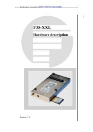
<strong>JP18</strong> <strong>GPS</strong>-Receiver<br />
Lead-free products<br />
<strong>Hardware</strong> description<br />
Version 1.0.7; Last Modified: Monday 25 January 2010
<strong>JP18</strong> <strong>FALCOM</strong> <strong>GPS</strong> RECEIVER VERSION 1.0.7<br />
Table of contents<br />
1 INTRODUCTION.......................................................................................5<br />
1.1 General.......................................................................................................................5<br />
1.2 Order options ..............................................................................................................5<br />
1.3 Used abbreviations......................................................................................................6<br />
1.4 Related documents.....................................................................................................6<br />
2 SECURITY..............................................................................................7<br />
2.1 General information.....................................................................................................7<br />
2.2 Restricted use.............................................................................................................7<br />
2.3 Children.......................................................................................................................7<br />
2.4 Operation/antenna.......................................................................................................7<br />
2.5 Electrostatic Discharge (ESD).....................................................................................8<br />
2.6 Moisture Sensitive Level (MSL)...................................................................................8<br />
3 SAFETY STANDARDS.................................................................................9<br />
4 TECHNICAL DATA...................................................................................10<br />
4.1 FEATURES...............................................................................................................10<br />
5 TECHNICAL DESCRIPTION........................................................................11<br />
5.1 Receiver Architecture................................................................................................11<br />
5.2 Product applications..................................................................................................11<br />
5.3 Technical specifications.............................................................................................12<br />
5.3.1 Electrical Characteristics.....................................................................................12<br />
5.4 Operational Modes....................................................................................................13<br />
5.5 Low Power Modes.....................................................................................................14<br />
5.5.1 NMEA input message for ATP Mode (Not available in ROM-Mode)....................15<br />
6 HARDWARE INTERFACE AND CONFIGURATION SIGNALS.....................................17<br />
6.1 <strong>JP18</strong> - QFN-Pin Configuration...................................................................................17<br />
6.2 Configuration and timing signals................................................................................19<br />
7 SOFTWARE INTERFACE............................................................................21<br />
7.1 SiRF binary data message........................................................................................21<br />
7.2 NMEA data message.................................................................................................22<br />
7.2.1 NMEA output messages......................................................................................22<br />
7.2.2 NMEA input messages........................................................................................22<br />
7.2.3 Transport Message..............................................................................................23<br />
8 MECHANICAL DRAW AND LAYOUT AND SOLDERING.........................................24<br />
8.1 RF connection...........................................................................................................25<br />
8.2 Solder profile requirements.......................................................................................26<br />
This confidential document is the property of <strong>FALCOM</strong> and may not be copied or circulated without permission.<br />
Page 2
<strong>JP18</strong> <strong>FALCOM</strong> <strong>GPS</strong> RECEIVER VERSION 1.0.7<br />
9 FIRST STEPS TO MAKE IT WORKS...............................................................27<br />
10 APPENDIX..........................................................................................29<br />
10.1 How to put the <strong>JP18</strong> into power saving modes?......................................................29<br />
Version history:<br />
This table provides a summary of the document revisions.<br />
Version Author Changes Modified<br />
1.0.7 F. Beqiri<br />
- Added power consumption in Hibernate/Standby state - see Figure 3.<br />
- SiRF input messages 0x82 and 0x95 are not supported - see Table 7.<br />
- SPI bus is not supported in the current software. Depending on purchase order quantity it is<br />
possible to make a variant of the software that supports the SPI interface. For more information<br />
please contact our sales department.<br />
25/01/2010<br />
1.0.6 F. Beqiri<br />
- Added key characteristics of power management modes, see chapter 5.5.2.<br />
- In the <strong>JP18</strong> hardware revision "4d", the ON/OFF pin is pulled low through a 47 kΩ.<br />
11/02/2009<br />
1.0.5 F. Beqiri - VRTC_REG_IN must be always connected to the VCC pin. 06/06/2008<br />
1.0.4 F. Beqiri<br />
- The firmware version ROM is very early (engineering proof) and was never intended for<br />
production use.<br />
23/05/2008<br />
1.0.3 F. Beqiri<br />
- Power consumption in the Hibernate state is replaced to “To be defined” - see Fig. 3.<br />
- The ON/OFF pin works only in the FLASH mode.<br />
17/03/2008<br />
1.0.2 F. Beqiri - <strong>JP18</strong> module can accept only one reflow process.<br />
- Replaced Fig.1 by a new one.<br />
25/09/2007<br />
- Added standards for handling ESD sensitive devices – see chapter 2.5.<br />
1.0.1 F. Beqiri - <strong>JP18</strong> module is classified as a MSL3 device – see chapter 2.6.<br />
- Throughout this documentation the input voltage range of VRTC_REG_IN and VCC has<br />
changed from 3.4 .. 5.5 to 3.3 .. 5.5 V.<br />
- Added description of pin ON/OFF- See chapter 6.2, page 22<br />
12/09/2007<br />
1.0.0 F. Beqiri - Initial version 05/07/2007<br />
This confidential document is the property of <strong>FALCOM</strong> and may not be copied or circulated without permission.<br />
Page 3
<strong>JP18</strong> <strong>FALCOM</strong> <strong>GPS</strong> RECEIVER VERSION 1.0.7<br />
Cautions<br />
Information furnished herein by <strong>FALCOM</strong> is believed to be accurate and reliable.<br />
However, no responsibility is assumed for its use. Also the information<br />
contained herein is subject to change without notice.<br />
Please, read carefully the safety precautions.<br />
If you have any technical questions regarding this document or the product described<br />
in it, please, contact your vendor.<br />
General information about <strong>FALCOM</strong> and its range of products is available at the<br />
following Internet address: http://www.falcom.de/<br />
Trademarks<br />
Some mentioned products are registered trademarks of their respective<br />
companies.<br />
Copyright<br />
This description is copyrighted by <strong>FALCOM</strong> Wireless Communications GmbH<br />
with all rights reserved. No part of this user’s guide may be produced in any form<br />
without the prior written permission of <strong>FALCOM</strong> Wireless Communications<br />
GmbH.<br />
<strong>FALCOM</strong> Wireless Communications GmbH<br />
The manufacture assumes no liability for any errors or discrepancies that may<br />
have occurred in preparation of this document.<br />
Note<br />
Specifications and information given in this document are subject to change<br />
by <strong>FALCOM</strong> without notice.<br />
This confidential document is the property of <strong>FALCOM</strong> and may not be copied or circulated without permission.<br />
Page 4
<strong>JP18</strong> <strong>FALCOM</strong> <strong>GPS</strong> RECEIVER VERSION 1.0.7<br />
1 INTRODUCTION<br />
1.1 General<br />
This description is focussed on the <strong>GPS</strong> <strong>receiver</strong> of the <strong>FALCOM</strong> <strong>JP18</strong> from<br />
<strong>FALCOM</strong>.<br />
The <strong>JP18</strong> architecture is based on the SiRFstarIII core (GSC3LTf chipset), the<br />
same industry-leading <strong>GPS</strong> DSP core design found all members of the GSC3<br />
family, but implemented in leading-edge 90 nm fabrication process<br />
technology, operating at 1.2V to provide superior performance and best-inclass<br />
power consumption.<br />
The new differentiating features that give the <strong>JP18</strong> its unique identity are: the<br />
new lower power SiRFstarIII-LT core, integrated 4 Mbits program ROM with ROM<br />
patch memory, UART, and a new highly optimized 11 mm x 11 mm multi-chip<br />
module with a height of 1.7 mm. The LNA is enabled and disables automatically<br />
from the software to lower overall power consumption when the <strong>receiver</strong> is not<br />
in use.<br />
The single board solution offered in 22-pin (11 mm x 11 mm) QFN mounting<br />
device is optimized for location applications requiring high performance in a<br />
very small form factor - ideal for devices with limited on-board processing<br />
power.<br />
The <strong>JP18</strong> concept builds perfect basis for the design of high-sensitive, lowpower,<br />
compact and cost efficient state-of-the-art <strong>GPS</strong> enabled system<br />
solutions for target platforms such as mobile phones, automotive systems,<br />
portable computing devices, and embedded consumer devices. The <strong>FALCOM</strong><br />
<strong>JP18</strong> is also designed to be entire products such as AVL tracking units,<br />
handheld <strong>GPS</strong>.<br />
1.2 Order options<br />
Figure 1: The top (left) and bottom (right) views of the <strong>FALCOM</strong> <strong>JP18</strong><br />
Name Description<br />
<strong>JP18</strong> Packaged in a 22-pin package QFN mounting<br />
Table 1: Ordering options<br />
This confidential document is the property of <strong>FALCOM</strong> and may not be copied or circulated without permission.<br />
Page 5
<strong>JP18</strong> <strong>FALCOM</strong> <strong>GPS</strong> RECEIVER VERSION 1.0.7<br />
1.3 Used abbreviations<br />
Abbreviation Description<br />
D<strong>GPS</strong> Differential <strong>GPS</strong><br />
DOP Dilution of Precision<br />
<strong>GPS</strong> Global Positioning System<br />
GGA <strong>GPS</strong> Fixed Data<br />
LNA Low Noise Amplifier<br />
NMEA National Maritime Electronics Association<br />
PRN Pseudo - Random Noise Number – The Identity of <strong>GPS</strong> satellites<br />
QFN Quad Flat No-lead<br />
RF Radio Frequency<br />
RP Receive Protocol<br />
RTC Real Time Clock<br />
RTCM Radio Technical Commission for Maritime Services<br />
SDI Data input<br />
SDO Data output<br />
SA Selective Availability<br />
WAAS Wide Area Augmentation System<br />
MSK Minimum Shift Keying<br />
PCB Printed Circuit Board<br />
PRN Pseudo-random noise<br />
IF Intermediate Frequency<br />
A/D Analog/Digital<br />
Table 2: Abbreviations<br />
1.4 Related documents<br />
[1.] SiRF binary and NMEA protocol specification;<br />
www.falcom.de│Support│Documentation│Sirf│SiRFmessages_SSIII.zip<br />
[2.] SiRF-demo software and <strong>manual</strong>;<br />
www.falcom.de│Support│Documentation│Sirf│SiRFdemo.pdf<br />
www.falcom.de│Support│Software & Tools│Sirf│Manual_SiRFdemoX.XX.zip<br />
[3.] AppNotes_<strong>JP18</strong>_gps_<strong>receiver</strong>.pdf<br />
[4.] <strong>GPS</strong>evaluationKitForJP13JP14JP15<strong>JP18</strong>FSA01_UserManualVer_1.03.pdf<br />
This confidential document is the property of <strong>FALCOM</strong> and may not be copied or circulated without permission.<br />
Page 6
<strong>JP18</strong> <strong>FALCOM</strong> <strong>GPS</strong> RECEIVER VERSION 1.0.7<br />
2 SECURITY<br />
This chapter contains important information for the safe and reliable use of the<br />
<strong>GPS</strong> <strong>receiver</strong>. Please read this chapter carefully before starting to use the <strong>GPS</strong><br />
<strong>receiver</strong>.<br />
2.1 General information<br />
The Global Positioning System uses satellite navigation, an entirely new concept<br />
in navigation. <strong>GPS</strong> has become established in many areas, for example, in civil<br />
aviation or deep-sea shipping. It is making deep inroads in vehicle<br />
manufacturing and before long everyone of us will use it this way or another.<br />
The <strong>GPS</strong> system is operated by the government of the United States of America,<br />
which also has sole responsibility for the accuracy and maintenance of the<br />
system. The system is constantly being improved and may entail modifications<br />
effecting the accuracy and performance of the <strong>GPS</strong> equipment.<br />
2.2 Restricted use<br />
Certain restrictions on the use of the <strong>GPS</strong> <strong>receiver</strong> may have to be observed on<br />
board a plane, in hospitals, public places or government institutions,<br />
laboratories etc. Follow these instructions.<br />
2.3 Children<br />
Do not allow children to play with the <strong>GPS</strong> <strong>receiver</strong>. It is not a toy and children<br />
could hurt themselves or others. The <strong>GPS</strong> <strong>receiver</strong> consists of many small parts<br />
which can come loose and could be swallowed by small children. Thoughtless<br />
handling can damage the <strong>GPS</strong> <strong>receiver</strong>.<br />
2.4 Operation/antenna<br />
Operate the <strong>GPS</strong> <strong>receiver</strong> with an antenna connected to it and with no<br />
obstruction between the <strong>receiver</strong> and the satellite.<br />
Make absolutely sure that the antenna socket or antenna cable is not shorted<br />
as this would render the <strong>GPS</strong> <strong>receiver</strong> non-functional.<br />
Do not use the <strong>receiver</strong> with a damaged antenna. Replace a damaged<br />
antenna without delay. Use only a manufacturer-approved antenna. Use only<br />
the supplied or an approved antenna with your <strong>GPS</strong> <strong>receiver</strong>. Antennas from<br />
other manufacturers which are not authorized by the supplier can damage the<br />
<strong>GPS</strong> <strong>receiver</strong>.<br />
Technical modifications and additions may contravene local radio-frequency<br />
emission regulations or invalidate the type approval.<br />
Authorized <strong>GPS</strong> antennas: FAL-ANT-3 (active antenna)<br />
This confidential document is the property of <strong>FALCOM</strong> and may not be copied or circulated without permission.<br />
Page 7
<strong>JP18</strong> <strong>FALCOM</strong> <strong>GPS</strong> RECEIVER VERSION 1.0.7<br />
2.5 Electrostatic Discharge (ESD)<br />
The <strong>JP18</strong> <strong>GPS</strong> <strong>receiver</strong> contains class 1 devices. The <strong>JP18</strong> module contains<br />
components that can be damaged or destroyed by electrostatic discharge.<br />
When handling the module, observe the necessary safety precautions against<br />
electrostatic discharge (ESD), in accordance with EN 61340-5-1 and the<br />
following. The following Electrostatic Discharge (ESD) precautions are<br />
recommended:<br />
- Protective outer garments.<br />
- Handle device in ESD safeguarded work area.<br />
- Transport device in ESD shielded containers.<br />
- Monitor and test all ESD protection equipment.<br />
- Treat the <strong>JP18</strong> <strong>GPS</strong> <strong>receiver</strong> as extremely sensitive to ESD.<br />
2.6 Moisture Sensitive Level (MSL)<br />
The <strong>JP18</strong> <strong>GPS</strong> <strong>receiver</strong> is classified as a MSL3 device. <strong>JP18</strong> is moisture sensitive<br />
and need to be handled within proper MSL3 guidelines to avoid damage from<br />
moisture absorption and exposure to solder reflow temperatures that can result<br />
in yield and reliability degradation. That means, after the module <strong>JP18</strong> is<br />
removed from the vacuum packaging, it must go through reflow for main<br />
board assembly within 168 hours (1 week). If this conditions is not met, the<br />
module should be baked for 24 hours at 125ºC before board mounting.<br />
References<br />
Customers may refer to following IPC standards for more details:<br />
➢ J-STD-033B Standard for Handling, Packing, Shipping and Use of<br />
Moisture/Reflow Sensitive Surface Mount Devices.<br />
➢ J-STD-020D Moisture/Reflow Sensitivity Classification for Non-hermetic Solid State<br />
Surface Mount Devices.<br />
This confidential document is the property of <strong>FALCOM</strong> and may not be copied or circulated without permission.<br />
Page 8
<strong>JP18</strong> <strong>FALCOM</strong> <strong>GPS</strong> RECEIVER VERSION 1.0.7<br />
3 SAFETY STANDARDS<br />
The <strong>GPS</strong> <strong>receiver</strong> meets the safety standards for RF <strong>receiver</strong>s and the standards<br />
and recommendations for the protection of public exposure to RF<br />
electromagnetic energy established by government bodies and professional<br />
organizations, such as directives of the European Community, Directorate<br />
General V in matters of radio frequency electromagnetic energy.<br />
This confidential document is the property of <strong>FALCOM</strong> and may not be copied or circulated without permission.<br />
Page 9
<strong>JP18</strong> <strong>FALCOM</strong> <strong>GPS</strong> RECEIVER VERSION 1.0.7<br />
4 TECHNICAL DATA<br />
4.1 FEATURES<br />
� <strong>GPS</strong>:<br />
� Size:<br />
� Weight:<br />
� TCXO:<br />
� On-Chip Memory:<br />
� OEM single board 20 channel <strong>GPS</strong> <strong>receiver</strong>.<br />
� 11 x 11 x 1.7 mm (L x B x H)<br />
� 0.5 gr<br />
� Operating Voltage:<br />
� Power Consumption:<br />
� Power Management:<br />
� Temperature Range:<br />
� ROM Operation:<br />
� FLASH Operation:<br />
� BOOTMODE:<br />
� ± 0.5 ppm<br />
� FLASH 4 Mbit<br />
� ROM 4 Mbit<br />
� +3.3 V ... + 5.5 V DC<br />
� approx. 27 mA (continuous mode)<br />
� 25 µA (Hibernate state)<br />
� Adaptive TricklePower (ATP) - for more details see<br />
chapter 5.5.1, page 16.<br />
� -20 to +70 °C (operation, transportation and storage).<br />
� Baudrate: 4800 bps,<br />
� Messages: (1x1 sec.)RMC, GGA, GSA; (1x5sec.) GSV -(1 x 5<br />
sec.)<br />
� Baudrate: 38400 bps,<br />
� Messages: RMC, GGA, GSA, GSV - (1 x 1 sec.)<br />
This confidential document is the property of <strong>FALCOM</strong> and may not be copied or circulated without permission.<br />
Page 10
<strong>JP18</strong> <strong>FALCOM</strong> <strong>GPS</strong> RECEIVER VERSION 1.0.7<br />
� To load a new firmware into the internal FLASH use<br />
SiRFflash tool version 3.2 or higher.<br />
This confidential document is the property of <strong>FALCOM</strong> and may not be copied or circulated without permission.<br />
Page 11
<strong>JP18</strong> <strong>FALCOM</strong> <strong>GPS</strong> RECEIVER VERSION 1.0.7<br />
5 TECHNICAL DESCRIPTION<br />
5.1 Receiver Architecture<br />
The <strong>JP18</strong> OEM <strong>GPS</strong> <strong>receiver</strong> from <strong>FALCOM</strong> is a new OEM <strong>GPS</strong> <strong>receiver</strong> product<br />
that features the SiRFstarIII single chipset. The core of <strong>JP18</strong> units is comprised of<br />
the GSC3LPf that includes the Digital and RF in a single chip. The SiRFstarIII-LT<br />
DSP core processes the incoming baseband samples and outputs <strong>GPS</strong> satellite<br />
pseudo-range measurements for storage in on-board SRAM. Once in DSP<br />
SRAM, the pseudo-range measurements are then available for further<br />
processing by the ARM7TDMI-S to calculate position, speed, heading, and time.<br />
The firmware for ARM7TDMI-S is stored and executed directly from either the onboard<br />
4 Mbit ROM or 4 Mbit FLASH memory. The calculated position, speed,<br />
heading, and time data is stored in CPU SRAM, which is then formatted in the<br />
selected data format (NMEA, SiRF Standard Binary (SSB), or AI3/F) for transfer to<br />
the host via the UART. In Assisted-<strong>GPS</strong> applications, the use of Location Protocol<br />
Libraries (provided by SiRF) running on the host, the navigation data can be<br />
converted to other industry standard location protocols such as RRLP, RRC,<br />
NMEA and PDDM.<br />
Figure 2: Receiver architecture of the <strong>JP18</strong> <strong>GPS</strong> <strong>receiver</strong>.<br />
Figure 2 above shows the block diagram of the <strong>JP18</strong> architecture.<br />
5.2 Product applications<br />
- Handheld <strong>GPS</strong> <strong>receiver</strong> applications<br />
- Automotive applications<br />
- Marine navigation applications<br />
- Aviation applications<br />
- Timing applications<br />
This confidential document is the property of <strong>FALCOM</strong> and may not be copied or circulated without permission.<br />
Page 12
<strong>JP18</strong> <strong>FALCOM</strong> <strong>GPS</strong> RECEIVER VERSION 1.0.7<br />
5.3 Technical specifications<br />
5.3.1 Electrical Characteristics<br />
� <strong>GPS</strong> features:<br />
� Horizontal position accuracy:<br />
� Datum:<br />
� Sensitivity:<br />
� O EM single board 20 channel <strong>GPS</strong> <strong>receiver</strong>, L1 1575.42<br />
MHz, C/A code 1,023 MHz chip rate.<br />
� <strong>GPS</strong> <strong>receiver</strong> with SiRFstarIII – GSC3LTf chip<br />
� Processor type ARM7/TDMI<br />
� A utonomous < 2.5 meters<br />
� SBAS
<strong>JP18</strong> <strong>FALCOM</strong> <strong>GPS</strong> RECEIVER VERSION 1.0.7<br />
5.4 Operational Modes<br />
External configuration inputs permit booting from on-chip boot loader, and<br />
internal flash memory. The default strap configuration for on-chip operational<br />
program ROM is provided by on-chip pullups so that external pull-ups are not<br />
required, saving cost and reducing footprint. Table 1 summarizes the program<br />
memory bootstrap configurations.<br />
DATA 0 DATA 1<br />
ROM Open Open<br />
FLASH Open Connect to GND<br />
BOOTMODE Connect to VIO Open<br />
Table 1: ROM and Flash Operating Mode<br />
Two basic functional modes are of primary concern to the system designer:<br />
ROM and Flash.<br />
● ROM mode. This is the default program memory out of which the <strong>JP18</strong><br />
<strong>receiver</strong> executes its <strong>GPS</strong> application firmware on reset.<br />
No external configuration inputs are required to select<br />
this mode. In this mode, the device is executing firmware<br />
directly from on-chip ROM. The on-chip cache-control<br />
hardware is used to provide a ROM patching facility.<br />
Important: The firmware version ROM is very early<br />
(engineering proof) and was never intended<br />
for production use.<br />
● FLASH mode. This is supported when the DATA 1 line is connected to<br />
GND (ground). On reset, the <strong>JP18</strong> <strong>receiver</strong> executes<br />
firmware directly from the FLASH memory. In this mode,<br />
the device is executing firmware directly from external<br />
non-volatile memory, such as FLASH. This is the<br />
secondary operational mode intended for those<br />
customers who want the flexibility of implementing<br />
software updates. The cache-controller hardware is<br />
used to accelerate read accesses from Flash.<br />
Flash Loader Mode<br />
This is provided to support flash loading. This mode is supported when the<br />
DATA 0 is connected to VIO pin. On reset, the <strong>JP18</strong> <strong>receiver</strong> is set into the<br />
Flash Loader Mode the flash loader program attempts to load the program<br />
to the internal flash via the on-board UART (RXA and TXA) before executing<br />
normal operations.<br />
<strong>GPS</strong> operational modes include: Acquisition, Tracking, and Clock Only.<br />
These modes are accessed and automatically managed through SiRF’s<br />
firmware products:<br />
Acquisition:<br />
RF is on; ARM processor is running; <strong>GPS</strong> DSP core is running highest<br />
duty cycle; RTC is running. This is the highest power consumption<br />
mode of the <strong>JP18</strong> <strong>GPS</strong> <strong>receiver</strong>.<br />
This confidential document is the property of <strong>FALCOM</strong> and may not be copied or circulated without permission.<br />
Page 14
<strong>JP18</strong> <strong>FALCOM</strong> <strong>GPS</strong> RECEIVER VERSION 1.0.7<br />
Tracking:<br />
RF is on; ARM processor is running; <strong>GPS</strong> DSP core is running lowest<br />
duty cycle; RTC is running. This is the second highest power<br />
consumption mode of the <strong>JP18</strong> <strong>GPS</strong> <strong>receiver</strong>, and this is the mode<br />
in which the <strong>JP18</strong> <strong>GPS</strong> <strong>receiver</strong> is expected to spend most of its<br />
operational time.<br />
Clock Only:<br />
Circuits are powered; clocks are gated to <strong>GPS</strong> DSP core; RF<br />
biases are removed from the <strong>receiver</strong> chain but the system clock<br />
is running; ARM processor is running; RTC is running.<br />
All three operational modes are available in both ROM and Flash<br />
functional modes.<br />
5.5 Low Power Modes<br />
In low power modes, the device is no longer acquiring and tracking satellites or<br />
providing navigation solutions. It is then desirable to lower power consumption<br />
by placing the device in either STANDBY or HIBERNATE state from the CLOCK<br />
ONLY state. These modes are accessed and automatically managed through<br />
SiRF firmware products:<br />
STANDBY:<br />
Circuits are powered; clocks are gated; RF biases are removed; RTC is<br />
running. This is the second lowest power consumption mode of the<br />
GSC3LT.<br />
HIBERNATE:<br />
External power is ON; RF and BB (baseband) core and IO voltages are OFF;<br />
RTC is running. This is the lowest power consumption mode of the GSC3LT.<br />
In hibernate state the <strong>receiver</strong> drives 25µA of current.<br />
All low power modes are available in Flash functional mode.<br />
Remark: The environment temperature may also affect the power consumption in the Standby state.<br />
Figure 3: Three system states into the ATP mode.<br />
This confidential document is the property of <strong>FALCOM</strong> and may not be copied or circulated without permission.<br />
Page 15
<strong>JP18</strong> <strong>FALCOM</strong> <strong>GPS</strong> RECEIVER VERSION 1.0.7<br />
The transition from Standby state back to the full power is generated through<br />
the internal RTC, which transmits a wake up signal to the <strong>GPS</strong> engine to switch it<br />
on. The <strong>JP18</strong> is woken up and begins to acquire the on view satellites and to<br />
collect their data. Under normal tracking conditions, the <strong>receiver</strong> is set for a<br />
specific update period (range from 1 to 10 seconds), and a specific sampling<br />
time during each period (range from 200 to 900 ms). The <strong>receiver</strong> turns to full<br />
power state for the sampling time to collect data, and then operates in<br />
Standby state for the remainder of the update period. The next full-power state<br />
is initiated by an RTC wakeup. But in harsh tracking environments the <strong>receiver</strong><br />
automatically switches to full power state to improve navigation performance.<br />
When the satellites are sorted according to their signal strength, the fourth<br />
satellite determines if the transition will occur or not. The threshold is 26 dB-Hz.<br />
When tracking, conditions return to normal (four or more satellites with C/No of<br />
30 dB-Hz or higher), the <strong>receiver</strong> switches back to the power saving mode.<br />
5.5.1 NMEA input message for ATP Mode<br />
( Not available in ROM-Mode)<br />
Power saving mode is disabled by default. In order to enable it, input the NMEA<br />
message in table below. The description of each parameter used for Adaptive<br />
TricklePower or Push-To-Fix is listed below. Key characteristics of power<br />
management modes is given in chapter 5.5.2. How these messages can be<br />
sent to the <strong>GPS</strong> unit, refer to chapter Appendix section 10.1 page 32.<br />
Syntax $PSRF107,,,,,,<br />
Examples<br />
$PSRF107,1,400,2000,60000,60000,1*17 // ATP mode<br />
$PSRF107,2,400,60000,60000,60000,0*21 // PTF mode<br />
$PSRF107,0,0,0,0,0,0*21 // back to Continuous mode<br />
Parameter Description<br />
<br />
Defines the mode to be performed. It can be set to:<br />
0 Sets the target <strong>receiver</strong> back to the Continuous<br />
mode (full power).<br />
1 Sets the target <strong>receiver</strong> into the Adaptive<br />
TricklePower (ATP) mode.<br />
2 Sets the target <strong>receiver</strong> into the Push-To-Fix (PTF)<br />
mode.<br />
<br />
Defines the OnTime period in milliseconds the <strong>receiver</strong> will stay in full<br />
power state until a position solution is made and estimated to be<br />
reliable. Please note that, in harsh tracking environments the<br />
<strong>receiver</strong> automatically switches to full power state to improve<br />
navigation performance even if the defined OnTime has been<br />
expired. When the satellites are sorted according their signal<br />
strength, the fourth satellite determines if the transition to Standby<br />
mode/hibernate state will occur or not. It can be set to a value<br />
between:<br />
200 ... 900 OnTime period in milliseconds<br />
This confidential document is the property of <strong>FALCOM</strong> and may not be copied or circulated without permission.<br />
Page 16
<strong>JP18</strong> <strong>FALCOM</strong> <strong>GPS</strong> RECEIVER VERSION 1.0.7<br />
<br />
Defines the complete interval of time in milliseconds the <strong>receiver</strong> will<br />
stay in full power and Standby mode/hibernate state.<br />
It can be set to a value between:<br />
1000 ... 10000 Interval of time in milliseconds intended for<br />
Adaptive TricklePower (ATP) mode.<br />
10000 ... 7200000 Interval of time in milliseconds intended for<br />
Push-To-Fix (PTF) mode.<br />
<br />
Specifies the Maximum Acquire Time in milliseconds how long the<br />
<strong>GPS</strong> <strong>receiver</strong> should attempt to acquire satellites and navigate. If<br />
this time elapses and no <strong>GPS</strong>-fix is obtained, the <strong>GPS</strong> <strong>receiver</strong> puts<br />
itself into the sleep mode for up to MaxOffTime in ms. It means, the<br />
<strong>GPS</strong> <strong>receiver</strong> searches for MaxAcqTime in ms, sleeps for MaxOffTime in<br />
ms, searches again for MaxAcqTime in ms, etc. It can be set to a<br />
value between:<br />
1000 ... No Limit<br />
<br />
Specifies the Maximum Off Time in milliseconds how long the target<br />
<strong>receiver</strong> should remain off (sleep mode) before making another<br />
attempt to navigate. This mode is enabled, if the target <strong>receiver</strong> is<br />
turned on and acquires satellites, but does not navigate. This mode<br />
is disabled, if the target <strong>receiver</strong> is turned on, acquires and<br />
navigates. It can be set to a value between:<br />
1000 .. 1800000<br />
<br />
Enables/disables the ATP mode if the value of the <br />
parameter is set to 1, otherwise it does not have any effect. It can<br />
be set to:<br />
<br />
0 Disables ATP mode.<br />
1 Enables ATP mode.<br />
CHECKSUM is a two-hex character as defined in the NMEA<br />
specification. Use of checksums is required on all input messages.<br />
For more detailed information, refer to the chapter 7.2.3 page 26.<br />
<br />
* Note:<br />
Each message is terminated using Carriage Return (CR) Line Feed<br />
(LF) which is hex 0D 0A. Because 0D 0A are not printable ASCII<br />
characters, they are omitted from the example strings, but must be<br />
sent to terminate the message and cause the <strong>receiver</strong> to process<br />
that input message.<br />
• SiRF recommends the use of 300 ms, 1-second or 400 ms, 2-second for<br />
optimum performance.<br />
This confidential document is the property of <strong>FALCOM</strong> and may not be copied or circulated without permission.<br />
Page 17
<strong>JP18</strong> <strong>FALCOM</strong> <strong>GPS</strong> RECEIVER VERSION 1.0.7<br />
5.5.2 Key characteristics of power management modes<br />
Key characteristics of power management modes are as follows:<br />
✔ Adaptive TricklePower (ATP) is a variant of TricklePower (TP). Only ATP is<br />
supported on <strong>JP18</strong> <strong>receiver</strong>. TP is intended to save power by cycling<br />
between full power, a reduced power setting using just the CPU, and a<br />
low-power setting in a fixed-rate cycle. Cycle times range between 1 and<br />
10 seconds (how to configure this mode, see chapter 5.5.1). TP provides<br />
deterministic power savings with constant output rate, but may suffer lost<br />
fixes in a weak-signal environment. ATP operates similar to TP. However,<br />
when signal levels drop, ATP returns to full power so that message output<br />
rates remain constant and valid fixes are attempted even in difficult<br />
environments. This results in variable power savings but much more reliable<br />
performance for a fixed output rate. Applications using ATP should give<br />
performance very similar to full power, but with significant power savings in<br />
strong-signal conditions. When Adaptive TricklePower (ATP) is enabled the<br />
<strong>receiver</strong> will maximize the navigation performance while running<br />
TricklePower. Under normal tracking conditions, ATP performs the same as<br />
TricklePower, but in harsh tracking environments the <strong>receiver</strong> automatically<br />
switches to full power state to improve navigation performance. When the<br />
satellites are sorted according to their signal strength, the fourth satellite<br />
determines if the transition will occur or not. Currently, the threshold is 26<br />
dB-Hz. When tracking conditions return to normal (four or more satellites<br />
with C/N0 of 30 dB-Hz or higher), the <strong>receiver</strong> switches back to<br />
TricklePower. Consequently, navigation results can be improved in harsh<br />
<strong>GPS</strong> environments at the cost of using more power.<br />
✔ Push-to-Fix (PTF) mode is designed for the application that requires<br />
infrequent position reporting. The <strong>receiver</strong> generally stays in a low-power<br />
mode, up to 2 hours, but wakes up periodically to refresh position, time,<br />
ephemeris data and RTC calibration. A position request acts as a wakeup<br />
to the <strong>receiver</strong>, which is then able to supply a position within the hot-start<br />
time specification. The PTF period is 30 minutes by default but can be<br />
programmed between 10 seconds and 2 hours (how to configure this<br />
mode, see chapter 5.5.1). When the PTF mode is enabled, upon power on<br />
or a new PTF cycle, the <strong>receiver</strong> will stay on full power until a good<br />
navigation solution is computed. The hibernate state will follow for the<br />
remainder of the period. If it takes 36 seconds to fix position and refresh<br />
ephemeris on the default period of 30 minutes, the <strong>receiver</strong> will sleep for<br />
the 29 minutes and 24 seconds. When the application needs a position<br />
report, it can pulse the ON_OFF pin to wake up the <strong>receiver</strong>. Please note<br />
that it should be done only when the <strong>receiver</strong> is in hibernate state. When<br />
the <strong>receiver</strong> wakes up because of the ON_OFF pin, a new PTF cycle begins<br />
resetting all variables related to handling the wakeup and sleep time.<br />
Whenever the <strong>receiver</strong> wakes up, it stays on in order to collect pertinent<br />
<strong>GPS</strong> data, such as ephemeris and almanac before going back to sleep.<br />
Its purpose is to gather relevant data so that hot start condition can be<br />
prepared when it wakes up the next time.<br />
To wake the <strong>JP18</strong> <strong>receiver</strong> (turn ON) from either a stand-by or hibernate state,<br />
only use the ON_OFF pin. A rising pulse for at least 63 µsecs. duration to this pin<br />
This confidential document is the property of <strong>FALCOM</strong> and may not be copied or circulated without permission.<br />
Page 18
<strong>JP18</strong> <strong>FALCOM</strong> <strong>GPS</strong> RECEIVER VERSION 1.0.7<br />
will put the <strong>receiver</strong> into hibernate state if it is on and wake up if it is in sleep<br />
state. This pin functionality is unreliable while in ATP mode due to potential race<br />
conditions between internal control and external timing and should not be<br />
used. Asserting this signal when the <strong>receiver</strong> is already awake can cause the<br />
<strong>receiver</strong> to behave improperly, or to hang up entirely. The GPIO8 pin can be<br />
monitored since when its level is low, the <strong>JP18</strong> <strong>receiver</strong> is either in a stand-by or<br />
hibernate state.<br />
This confidential document is the property of <strong>FALCOM</strong> and may not be copied or circulated without permission.<br />
Page 19
<strong>JP18</strong> <strong>FALCOM</strong> <strong>GPS</strong> RECEIVER VERSION 1.0.7<br />
6 HARDWARE INTERFACE AND CONFIGURATION<br />
SIGNALS<br />
6.1 <strong>JP18</strong> - QFN-Pin Configuration<br />
Note the orientation of pins on the <strong>JP18</strong> <strong>receiver</strong>. When viewing the back side<br />
on the <strong>JP18</strong> <strong>receiver</strong>, you will see a cut pad on the lower-right-corner. Given<br />
this viewing orientation (see fig. 7), Pad 22 is on the right-bottom and Pad 1 is on<br />
the bottom-right.<br />
Figure 4: <strong>JP18</strong> pin identification<br />
PAD Name I/O Description Level<br />
1 GPIO 0 I/O User defined GPIO 1.8 V<br />
2 VRTC_REG_IN I Power for RTC and SRAM. It must be always connected to<br />
the VCC pin.<br />
3 ON/OFF I In the hardware revision "4d", this pin is internally pulled low<br />
through a 47 kΩ resistor. If not used leave it open. For<br />
detailed information about this pin, see description in chapter<br />
6.2, page 22.<br />
3.3 V – 5.5 V<br />
4 VRF O Output RF-regulator 2.7 V; Imax = 10 mA<br />
5 VANT I Power-supply for the active <strong>GPS</strong> antenna. Vin = 2.7V - 5V; Imax =20 mA<br />
6 GND - Ground 0 V<br />
7 RF_IN I RF-Input, L1, 1575,42 MHz 50 Ohms @ 1575,42 MHz<br />
8 GND - Ground 0 V<br />
1.2 V<br />
9 WAKEUP O Regulator Power Down Output. Active low 1.2 V<br />
10 TM O Time Mark Output (1 PPS) 1.8 V<br />
11 RXA I RS232 line (receive data) 1.8 V<br />
12 TXA O RS232 line (transmit data) 1.8 V<br />
13 RES I System Reset Input. Connect to GND for RESET. 1.2 V<br />
14 SPI_DI I SPI-Data-IN<br />
15 SPI_DO O SPI-Data-OUT<br />
Not supported in the current<br />
1.8 V<br />
16 SPI_CS O SPI-Chip-Select<br />
software.<br />
1.8 V<br />
1.8 V<br />
17 SPI_CLK I SPI-Clock 1.8 V<br />
18 DATA 0 I Input at startup. See Table 1: 1.8 V<br />
This confidential document is the property of <strong>FALCOM</strong> and may not be copied or circulated without permission.<br />
Page 20
<strong>JP18</strong> <strong>FALCOM</strong> <strong>GPS</strong> RECEIVER VERSION 1.0.7<br />
PAD Name I/O Description Level<br />
19 DATA 1 I Input at startup. SeeTable 1: 1.8 V<br />
20 VCC I Main input power supply. To eliminate unwanted ripple on<br />
the supply voltage, it is recommended that the power supply<br />
be filtered by a 10uF/10V capacitor to ground.<br />
21 VIO O Output voltage for IO-Block 1.8 V<br />
22 GPIO 8 I User defined GPIO 1.8 V<br />
Table 3: <strong>JP18</strong> - Ball description<br />
3.3 V – 5.5 V<br />
This confidential document is the property of <strong>FALCOM</strong> and may not be copied or circulated without permission.<br />
Page 21
<strong>JP18</strong> <strong>FALCOM</strong> <strong>GPS</strong> RECEIVER VERSION 1.0.7<br />
6.2 Configuration and timing signals<br />
Pin Name Description<br />
RES Provides an active-low (GND) reset input to the board. It<br />
causes the board to reset and to restart searching for satellites.<br />
If not used, leave it open.<br />
TM Provides 1 pulse per second output from the board, which is<br />
synchronized to within 1 microsecond of <strong>GPS</strong> time. The output<br />
is a 1.8 V level signal.<br />
RXA Receiving channel. It is used to receive software commands to<br />
the board from SiRFdemo software or from user written<br />
software.<br />
TXA Transmitting channel. It is used to output navigation and<br />
measurement data to SiRFdemo or user written software.<br />
VCC Main DC power supply in range from 3.3 V – 5.5 V DC used to<br />
power the <strong>JP18</strong> <strong>receiver</strong>.<br />
RF_IN Used to be connected directly an active antenna. The<br />
integrated low-noise amplifier of the active antenna can be<br />
supplied with the voltage provided by the VANT pin.<br />
Caution: Never connect or disconnect the antenna while the<br />
<strong>JP18</strong> is in use.<br />
Caution: Never supply any voltage on the RF_IN pin. This pin is<br />
always fed from the VANT pin.<br />
VANT Input line reserved for supplying power to an active antenna<br />
connected to the unit. The antenna bias for a connected<br />
active antenna can be provided in two way:<br />
✔ Using a 5 V active <strong>GPS</strong> antenna, connect the VANT pin<br />
to a 5 V power source.<br />
✔ Or connect the VRF output pin to VANT pin to apply<br />
2.7V to the antenna line. The VRF pin outputs 2.7V<br />
when the <strong>receiver</strong> is on and not sleeping.<br />
Hint: The input voltage on the VANT should be chosen in<br />
according to the antenna to be used.<br />
Note: The <strong>GPS</strong> <strong>receiver</strong> <strong>JP18</strong> has to be connected to an active<br />
<strong>GPS</strong> antenna with a max. current 20mA (10mA, if using VRF).<br />
VRF Provides +2.7V DC, and it can be connected to the VANT, to<br />
supply power to an active <strong>GPS</strong> antenna (max. 10 mA)<br />
connected to the <strong>GPS</strong> <strong>receiver</strong>.<br />
ON/OFF ON/OFF input to the internal Finite State Machine is at 1.2 V<br />
level and offers ON and OFF functions described below.<br />
Note that, the ON/OFF functions work only in FLASH mode, and<br />
not in ROM mode.<br />
The RTC clock must be on and stable for this control to be<br />
functional. Minimum on pulse duration is two RTC ticks, about<br />
This confidential document is the property of <strong>FALCOM</strong> and may not be copied or circulated without permission.<br />
Page 22
<strong>JP18</strong> <strong>FALCOM</strong> <strong>GPS</strong> RECEIVER VERSION 1.0.7<br />
63 μs. Minimum inter-pulse interval is one second. Minimum off<br />
duration is two RTC ticks, about 63 μs. The functions described<br />
assume that power to various sections (RF, IO, LNA) is<br />
controlled through the power management control pin<br />
WAKEUP.<br />
Mode Receiver state Pulse to ON/OFF New state result of pulse to ON/OFF<br />
Main supplies are OFF OFF<br />
Do not attempt. Possible part<br />
damage due if excessive<br />
current is forced into the pin.<br />
Stays off<br />
Hibernate: RF, IO, BB off, VRTC on Hibernate OK Awakening<br />
Full Power GSW/SLC ON and running OK Transitions to Hibernate<br />
Full Power GSW/SLC Hibernate Awakens to Full-power<br />
Adaptive Trickle Power GSW Duty cycle ON<br />
Adaptive Trickle Power GSW Duty cycle OFF<br />
Push-To-Fix GSW ON and running<br />
Do not attempt because of<br />
possible race conditions.<br />
Do not attempt because of<br />
possible race conditions.<br />
Do not attempt because of<br />
possible race conditions.<br />
Push-to-Fix GSW Hibernate<br />
Must verify by monitoring<br />
voltages that <strong>receiver</strong> is in<br />
Hibernate.<br />
ON<br />
Advanced Power Management SLC Hibernate OK ON<br />
Advanced Power Management SLC ON* OK* Hibernate<br />
Indeterminate due to timing of pulse<br />
with respect to internal asynchronous<br />
mode changes<br />
Indeterminate due to timing of pulse<br />
with respect to internal asynchronous<br />
mode changes<br />
Indeterminate - if <strong>receiver</strong> is on, it will<br />
be turned off, if turning off, it will be<br />
turned back on<br />
* With SLC firmware, when in HIBERNATE, the controlling code must verify<br />
that APM is enabled, and verify that all sessions are closed. The<br />
controlling code must also allow for a 1 second delay after session is<br />
closed, before any attempt to externally awaken the <strong>receiver</strong>.<br />
This pin is internally pulled low through a 47 kΩ resistor on the <strong>JP18</strong><br />
hardware and not on FSA02. Therefore, on FSA02 this pin should be<br />
pulled low thought a a ~47 kΩ resistor.<br />
Since it is a direct link to the core, this pin is limited to 1.2V. This is not a<br />
fail safe pin. The 1.2V VRTC power and clock should always be on and<br />
stable before this signal is asserted.<br />
The minimum inter-pulse interval is recommended as one second to<br />
allow time for the <strong>receiver</strong> to change modes in response to the<br />
preceding pulse. This requires that any activation of ON/OFF by<br />
mechanical switches must use suitable de-bouncing techniques to<br />
achieve minimum pulse duration and minimum inter-pulse interval.<br />
This confidential document is the property of <strong>FALCOM</strong> and may not be copied or circulated without permission.<br />
Page 23
<strong>JP18</strong> <strong>FALCOM</strong> <strong>GPS</strong> RECEIVER VERSION 1.0.7<br />
7 SOFTWARE INTERFACE<br />
The <strong>FALCOM</strong> <strong>JP18</strong> supports NMEA-0183 and SiRF binary protocols. A short<br />
description of these protocols is provided herein.<br />
For more detailed information about the messages listed in tables below, please<br />
refer to the SiRFstarIII message set specification available in the section<br />
“Support/Downloads/Documentation/SiRF/SiRFmessages_SSIII.zip” at <strong>FALCOM</strong><br />
homepage.<br />
7.1 SiRF binary data message<br />
Table 6 lists the messages for the SiRF output<br />
Hex ASCII Name Description<br />
0 x 02 2 Measured Navigation Data Position, velocity and time<br />
0 x 03 3 True Tracker Data Not implemented<br />
0 x 04 4 Measured Tracking Data Satellite and C/No information<br />
0 x 06 6 SW Version Receiver software<br />
0 x 07 7 Clock Status Current clock status<br />
0 x 08 8 50 BPS Subframe Data Standard ICD format<br />
0 x 09 9 Throughput Navigation complete data<br />
0 x 0A 10 Error ID Error coding for message failure<br />
0 x 0B 11 Command Acknowledgement Successful request<br />
0 x 0C 12 Command No Acknowledgement Unsuccessful request<br />
0 x 0D 13 Visible List Auto Output<br />
0 x 0E 14 Almanac Data Response to Poll<br />
0 x 0F 15 Ephemeris Data Response to Poll<br />
0 x 10 16 Test Mode 1 For use with SiRFtest (Test Mode 1)<br />
0 x 12 18 Ok To Send CPU ON/OFF (Trickle Power)<br />
0 x 13 19 Navigation Parameters Response to Poll<br />
0 x 14 20 Test Mode 2 Additional test data (Test Mode 2)<br />
0 x 1C 28 Nav. Lib. Measurement Data Measurement Data<br />
0 x 1E 30 Nav. Lib. SV State Data Satellite State Data<br />
0 x 1F 31 Nav. Lib. Initialization Data Initialization Data<br />
0 x FF 255 Development Data Various status messages<br />
Table 6: SiRF Output Messages<br />
Table 7 lists the message list for the SiRF input messages.<br />
Hex ASCII Name Description<br />
0 x 55 85 Transmit Serial Message User definable message<br />
0 x 80 128 Initialize Data Source Receiver initialization and associated parameters<br />
0 x 81 129 Switch to NMEA Protocol Enable NMEA message, output rate and baud rate<br />
0 x 82 130 Set Almanac (upload) Sends an existing almanac file to the <strong>receiver</strong> (not supported)<br />
0 x 84 132 Software Version (Poll) Polls for the loaded software version<br />
0 x 86 134 Set Main Serial Port Baud rate, data bits, stop bits and parity<br />
0 x 87 135 Switch Protocol Obsolete<br />
0 x 88 136 Mode Control Navigation mode configuration<br />
0 x 89 137 DOP Mask Control DOP mask selection and parameters<br />
0 x 8B 139 Elevation Mask Elevation tracking and navigation masks<br />
0 x 8C 140 Power Mask Power tracking and navigation masks<br />
0 x 8D 141 Editing Residual Not implemented<br />
0 x 8E 142 Steady-State Detection – not used Not implemented<br />
0 x 8F 143 Static Navigation Configuration for static operation<br />
0 x 90 144 Poll Clock Status (Poll) Polls the clock status<br />
0 x 92 146 Poll Almanac Polls for almanac data<br />
0 x 93 147 Poll Ephemeris Polls for ephemeris data<br />
0 x 94 148 Flash Update On the fly software update<br />
This confidential document is the property of <strong>FALCOM</strong> and may not be copied or circulated without permission.<br />
Page 24
<strong>JP18</strong> <strong>FALCOM</strong> <strong>GPS</strong> RECEIVER VERSION 1.0.7<br />
Hex ASCII Name Description<br />
0 x 95 149 Set Ephemeris (upload) Sends an existing ephemeris to the <strong>receiver</strong> (not supported)<br />
0 x 96 150 Switch Operating Mode Test mode selection, SV ID and period<br />
0 x 97 151 Set Trickle Power Parameters Push to fix mode, duty cycle and on time<br />
0 x 98 152 Poll Navigation Parameters Polls for the current navigation parameters<br />
0 x A5 165 Set UART Configuration Protocol selection, baud rate, data bits, stop bits and parity<br />
0 x A6 166 Set Message Rate SiRF binary message output rate<br />
0 x A7 167 Low Power Acquisition Parameters Low power configuration parameters<br />
0 x B6 182 Set UART Configuration Obsolete<br />
Table 7: SiRF Input Messages<br />
7.2 NMEA data message<br />
7.2.1 NMEA output messages<br />
Table 8 lists all NMEA output messages supported by SiRFstarIII evaluation<br />
<strong>receiver</strong> and a brief description.<br />
Option Description<br />
GGA Time, position and fix type data.<br />
GLL Latitude, longitude, UTC time of position fix and status.<br />
GSA <strong>GPS</strong> <strong>receiver</strong> operating mode, satellites used in the position solution and DOP values.<br />
GSV The number of <strong>GPS</strong> satellites in view satellite ID numbers, elevation, azimuth and SNR values.<br />
RMC Time, date, position, course and speed data.<br />
Table 8: NMEA Output Messages<br />
7.2.2 NMEA input messages<br />
Message MID 1<br />
Description<br />
Set Serial Port 100 Set PORT A parameters and protocol<br />
Navigation Initialization 101 Parameters required for start using X/Y/Z2 Query/Rate Control 103 Query standard NMEA message and/or set output rate<br />
LLA Navigation Initialization 104 Parameters required for start using Lat/Lon/Alt3 Development Data On/Off 105 Development Data messages On/Off<br />
MSK Receiver Interface MSK Command message to a MSK radio-beacon <strong>receiver</strong>.<br />
Table 9: MEA Input Messages<br />
1.Message Identification (MID).<br />
2.Input co-ordinates must be WGS84.<br />
3.Input co-ordinates must be WGS84.<br />
Note: NMEA input messages 100 to 105 are SiRF proprietary. The MSK<br />
NMEA string is as defined by the NMEA 0183 standard.<br />
This confidential document is the property of <strong>FALCOM</strong> and may not be copied or circulated without permission.<br />
Page 25
<strong>JP18</strong> <strong>FALCOM</strong> <strong>GPS</strong> RECEIVER VERSION 1.0.7<br />
7.2.3 Transport Message<br />
Start Sequence Payload Checksum End Sequence<br />
$PSRF 1 Data 2 *CKSUM 3 4<br />
1. Message Identifier consisting of three numeric characters. Input<br />
messages begin at MID 100.<br />
2. Message specific data. Refer to a specific message section for<br />
... definition.<br />
3. CHECKSUM is a two-hex character checksum as defined in the NMEA<br />
specification. Use of checksums is required on all input messages.<br />
4. Each message is terminated using Carriage Return (CR) Line Feed (LF)<br />
which is \r\n which is hex 0D 0A. Because \r\n are not printable ASCII<br />
characters, they are omitted from the example strings, but must be<br />
sent to terminate the message and cause the <strong>receiver</strong> to process that<br />
input message.<br />
CheckSum<br />
The checksum is 15-bit checksum of the bytes in the payload data. The<br />
following pseudo code defines the algorithm used.<br />
Let message to be the array of bytes to be sent by the transport.<br />
Let msgLen be the number of bytes in the message array to be<br />
transmitted.<br />
Clearly to say, the string over which the checksum has to be calculated is<br />
between the “$” and “*” (without characters “$” and “*”).<br />
Index = first<br />
checkSum = 0<br />
while index < msgLen<br />
checkSum = checkSum + message[index]<br />
checkSum = checkSum AND (2 15 -1).<br />
Note: All fields in all proprietary NMEA messages are required, none are<br />
optional. All NMEA messages are comma delimited.<br />
This confidential document is the property of <strong>FALCOM</strong> and may not be copied or circulated without permission.<br />
Page 26
<strong>JP18</strong> <strong>FALCOM</strong> <strong>GPS</strong> RECEIVER VERSION 1.0.7<br />
8 MECHANICAL DRAW AND LAYOUT AND<br />
SOLDERING<br />
The following chapters describe the mechanical dimensions of <strong>JP18</strong> and give<br />
recommendations for integrating of the <strong>JP18</strong> into your application platform.<br />
Note that, the absolute maximum dimension for <strong>JP18</strong> module is: 11.0 mm x 11.0<br />
mm (L x B) with a dimension tolerance of ±0.1 mm.<br />
Figure below shows the bottom view on <strong>JP18</strong> and provides an overview of the<br />
mechanical dimensions of the pointed pins.<br />
Figure 5: The mechanical draw of the <strong>JP18</strong> <strong>receiver</strong><br />
This confidential document is the property of <strong>FALCOM</strong> and may not be copied or circulated without permission.<br />
Page 27
<strong>JP18</strong> <strong>FALCOM</strong> <strong>GPS</strong> RECEIVER VERSION 1.0.7<br />
8.1 RF connection<br />
The <strong>JP18</strong> <strong>GPS</strong> <strong>receiver</strong> is designed to be functional by using either a passive<br />
patch antenna or an antenna connector with standard RF cables.<br />
Figure 6: RF connection to antenna feed of the <strong>JP18</strong> <strong>GPS</strong> <strong>receiver</strong> (bottom view)<br />
Recommendations for layout, and soldering. Please note that, the dimension<br />
tolerance is ±0.1 mm.<br />
Figure 7: Recommendations for layout (<strong>JP18</strong>).<br />
This confidential document is the property of <strong>FALCOM</strong> and may not be copied or circulated without permission.<br />
Page 28
<strong>JP18</strong> <strong>FALCOM</strong> <strong>GPS</strong> RECEIVER VERSION 1.0.7<br />
8.2 Solder profile requirements<br />
Figure 8 shows the recommended solder profile for Pb-free <strong>JP18</strong> unit.<br />
Figure 8: Typical solder conditions (temperature profile, reflow conditions).<br />
Consider for a long time in the soldering zone (with temperature higher than<br />
217 °C) has to be kept as short as possible to prevent component and substrate<br />
damages. Peak temperature must not exceed 250 °C.<br />
Please note that this soldering profile is a reference to the soldering<br />
machine <strong>FALCOM</strong> utilizes. This profile can vary by using different paste<br />
types, and soldering machines, and it should be adapted to the customer<br />
application. NO liability is assumed for any damage to the module caused<br />
while soldering.<br />
Reflow profiles in tabular form<br />
Profile Feature Values<br />
Ramp-Up Rate < 3 K/second<br />
Preheat- zone<br />
– Temperature Range<br />
– Time<br />
Peak-zone:<br />
– Peak Temperature<br />
– Time above 217°C<br />
160-180°C<br />
100-120 seconds<br />
240°C .. 250°C max.<br />
65-75 seconds<br />
Ramp-Down Rate < 3 K/second<br />
Note: <strong>JP18</strong> module can accept only one reflow process.<br />
This confidential document is the property of <strong>FALCOM</strong> and may not be copied or circulated without permission.<br />
Page 29
<strong>JP18</strong> <strong>FALCOM</strong> <strong>GPS</strong> RECEIVER VERSION 1.0.7<br />
9 PUTTING THE RECEIVER INTO OPERATION - FIRST<br />
STEPS<br />
For basic operation, only the four connections are necessary. These are:<br />
✔ A <strong>GPS</strong> antenna<br />
✔ Power supply for active antenna<br />
✔ A bi-directional voltage translation for 1.8V and 3.3 V<br />
✔ Power supply and RTC<br />
Figure 9: FXL translator circuit<br />
To provide a suitable operating environment and to prevent damage avoid:<br />
✔ Frequent exposure to water<br />
✔ Extreme temperatures (+70° C)<br />
✔ High vibration environments<br />
Antenna<br />
The antenna connection is the most critical part of PCB routing. Before placing<br />
the <strong>JP18</strong> on the PCB, make sure that the connection to the antenna signals is<br />
routed. In order to make it properly functional, a control impedance line has to<br />
connect the RF_IN signal with antenna feed points or antenna connector,<br />
respectively. The routing on the PCB depends on your choice.<br />
Power<br />
The input power is also very important as far as the minimum and maximum<br />
voltage is concerned. The power supply of <strong>JP18</strong> has to be a single voltage source<br />
of VCC at 3.3V to 5.5 VDC. Connect the GND pins to ground, and the VCC pin to<br />
a 3.3V..5.5 VDC power source. To eliminate unwanted ripple on the supply<br />
voltage, it is recommended that the power supply be filtered by a<br />
10uF/10V capacitor to ground (as shown in figure above). The capacitor<br />
should be placed as close as possible to the module’s power supply pin. If<br />
they are correctly connected, the board is full powered and the unit begins<br />
obtaining its position fix.<br />
This confidential document is the property of <strong>FALCOM</strong> and may not be copied or circulated without permission.<br />
Page 30
<strong>JP18</strong> <strong>FALCOM</strong> <strong>GPS</strong> RECEIVER VERSION 1.0.7<br />
Serial Interface<br />
The UART (RXA and TXA) is used as a host interface and debug interface<br />
between the host and <strong>JP18</strong> <strong>receiver</strong>. This interface is provided with two wires<br />
the RXA and TXA lines. These pins are 1.8 V. So you need a voltage translator for<br />
RX and TX lines to convert their voltage level from 1.8V to VCC (see Fig. 9<br />
above).<br />
The quickest way to get first results with the <strong>JP18</strong> is to use the <strong>JP18</strong> Evaluation<br />
board together with the program SiRFdemo.<br />
Figure 10: Evaluation board with connected <strong>JP18</strong> <strong>GPS</strong> <strong>receiver</strong> (without antenna connected).<br />
The Evaluation board contains:<br />
- Evaluation Box,<br />
- <strong>JP18</strong> sample with soldered antenna connector,<br />
- an additional not soldered <strong>JP18</strong> <strong>receiver</strong>,<br />
- power supply (AC/DC adapter, Type FW738/05, Output 5VDC 1.3 A),<br />
- active <strong>GPS</strong> antenna (FAL-ANT-3),<br />
- RS232 cable to your computer,<br />
- Evaluation board user’s <strong>manual</strong>.<br />
The Evaluation board with contained components are not included in the<br />
delivery package. The Evaluation board will have to be purchased separately.<br />
The SiRFdemo <strong>manual</strong> and software are available on <strong>FALCOM</strong>’s Website for<br />
free download:<br />
� www.falcom.de│Support│Documentation│Sirf│SiRFdemo.pdf<br />
� www.falcom.de│Support│Documentation│Sirf│SiRFdemo.zip<br />
This confidential document is the property of <strong>FALCOM</strong> and may not be copied or circulated without permission.<br />
Page 31
<strong>JP18</strong> <strong>FALCOM</strong> <strong>GPS</strong> RECEIVER VERSION 1.0.7<br />
10 APPENDIX<br />
10.1 How to put the <strong>JP18</strong> into power saving modes?<br />
By means of SiRFdemo software version 3.81 from SiRF the user is able to<br />
configure this operation mode with desired setting.<br />
The input message is accepted if the <strong>GPS</strong> <strong>receiver</strong> operates in the NMEA<br />
mode, else the input message will be ignored. The commands above cannot<br />
be implemented if the target <strong>receiver</strong> operates in the SiRF Binary mode.<br />
In order to set the <strong>receiver</strong> into the ATP mode via input messages, start the<br />
SiRFdemo software version 3.81, select the COM port where <strong>GPS</strong> <strong>receiver</strong> is<br />
connected and the baud rate to 38400 bps (for FLASH mode) or 4800 bps (for<br />
ROM mode), then open the COM port (for detailed information refer to the<br />
“<strong>GPS</strong>evaluationKitForJP13JP14JP15_UserManualVer_1.xx.pdf” document).<br />
If the <strong>receiver</strong> is operating in SiRF binary mode, switch it to the NMEA mode,<br />
select Switch to NMEA protocol from the Action menu of main window. After<br />
the <strong>receiver</strong> has obtained a <strong>GPS</strong> fix, it is able to be set in the ATP mode. To do<br />
this, open Action menu from main window and start Transmit Serial Message<br />
…. On the appeared dialog box select NMEA… protocol from the Protocol<br />
Wrapper option and type the following command onto the memo field as<br />
in Fig. 11:<br />
PSRF107,1,400,2000,60000,60000,1 (Sets the target <strong>receiver</strong> into the ATP<br />
mode. Excluding $-sign and checksum)<br />
After the message is correctly typed, send the defined message to the target unit by<br />
clicking the SEND button. The target device responds with Acknowledged … if the sent<br />
message is accepted by the target unit.<br />
Figure 11: Transmit a NMEA message to the target unit.<br />
To set the target <strong>receiver</strong> back to the full power mode just transmit the<br />
following message:<br />
PSRF107,0,0,0,0,0,0 // Sets the target <strong>receiver</strong> back to full power mode<br />
For more information, how to send the SiRF Binary or NMEA messages to the target unit,<br />
please refer to the SiRFstarIII message set specification available in the section<br />
“Support/Documentation/SiRF/SiRFmessages_SSIII.zip” at <strong>FALCOM</strong> homepage.<br />
This confidential document is the property of <strong>FALCOM</strong> and may not be copied or circulated without permission.<br />
Page 32