FALCOM JP18 GPS receiver - Hardware manual
FALCOM JP18 GPS receiver - Hardware manual
FALCOM JP18 GPS receiver - Hardware manual

Create successful ePaper yourself
Turn your PDF publications into a flip-book with our unique Google optimized e-Paper software.
<strong>JP18</strong> <strong>FALCOM</strong> <strong>GPS</strong> RECEIVER VERSION 1.0.7<br />
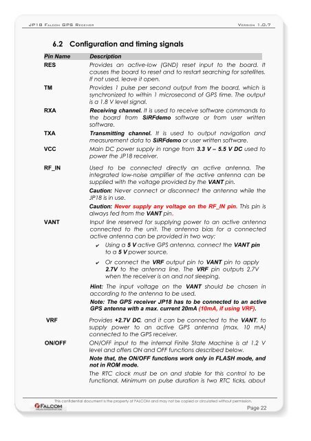
6.2 Configuration and timing signals<br />
Pin Name Description<br />
RES Provides an active-low (GND) reset input to the board. It<br />
causes the board to reset and to restart searching for satellites.<br />
If not used, leave it open.<br />
TM Provides 1 pulse per second output from the board, which is<br />
synchronized to within 1 microsecond of <strong>GPS</strong> time. The output<br />
is a 1.8 V level signal.<br />
RXA Receiving channel. It is used to receive software commands to<br />
the board from SiRFdemo software or from user written<br />
software.<br />
TXA Transmitting channel. It is used to output navigation and<br />
measurement data to SiRFdemo or user written software.<br />
VCC Main DC power supply in range from 3.3 V – 5.5 V DC used to<br />
power the <strong>JP18</strong> <strong>receiver</strong>.<br />
RF_IN Used to be connected directly an active antenna. The<br />
integrated low-noise amplifier of the active antenna can be<br />
supplied with the voltage provided by the VANT pin.<br />
Caution: Never connect or disconnect the antenna while the<br />
<strong>JP18</strong> is in use.<br />
Caution: Never supply any voltage on the RF_IN pin. This pin is<br />
always fed from the VANT pin.<br />
VANT Input line reserved for supplying power to an active antenna<br />
connected to the unit. The antenna bias for a connected<br />
active antenna can be provided in two way:<br />
✔ Using a 5 V active <strong>GPS</strong> antenna, connect the VANT pin<br />
to a 5 V power source.<br />
✔ Or connect the VRF output pin to VANT pin to apply<br />
2.7V to the antenna line. The VRF pin outputs 2.7V<br />
when the <strong>receiver</strong> is on and not sleeping.<br />
Hint: The input voltage on the VANT should be chosen in<br />
according to the antenna to be used.<br />
Note: The <strong>GPS</strong> <strong>receiver</strong> <strong>JP18</strong> has to be connected to an active<br />
<strong>GPS</strong> antenna with a max. current 20mA (10mA, if using VRF).<br />
VRF Provides +2.7V DC, and it can be connected to the VANT, to<br />
supply power to an active <strong>GPS</strong> antenna (max. 10 mA)<br />
connected to the <strong>GPS</strong> <strong>receiver</strong>.<br />
ON/OFF ON/OFF input to the internal Finite State Machine is at 1.2 V<br />
level and offers ON and OFF functions described below.<br />
Note that, the ON/OFF functions work only in FLASH mode, and<br />
not in ROM mode.<br />
The RTC clock must be on and stable for this control to be<br />
functional. Minimum on pulse duration is two RTC ticks, about<br />
This confidential document is the property of <strong>FALCOM</strong> and may not be copied or circulated without permission.<br />
Page 22