FALCOM JP18 GPS receiver - Hardware manual
FALCOM JP18 GPS receiver - Hardware manual
FALCOM JP18 GPS receiver - Hardware manual

You also want an ePaper? Increase the reach of your titles
YUMPU automatically turns print PDFs into web optimized ePapers that Google loves.
<strong>JP18</strong> <strong>FALCOM</strong> <strong>GPS</strong> RECEIVER VERSION 1.0.7<br />
8 MECHANICAL DRAW AND LAYOUT AND<br />
SOLDERING<br />
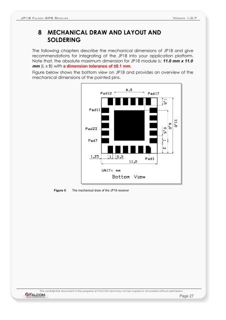
The following chapters describe the mechanical dimensions of <strong>JP18</strong> and give<br />
recommendations for integrating of the <strong>JP18</strong> into your application platform.<br />
Note that, the absolute maximum dimension for <strong>JP18</strong> module is: 11.0 mm x 11.0<br />
mm (L x B) with a dimension tolerance of ±0.1 mm.<br />
Figure below shows the bottom view on <strong>JP18</strong> and provides an overview of the<br />
mechanical dimensions of the pointed pins.<br />
Figure 5: The mechanical draw of the <strong>JP18</strong> <strong>receiver</strong><br />
This confidential document is the property of <strong>FALCOM</strong> and may not be copied or circulated without permission.<br />
Page 27