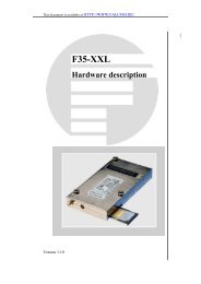
FALCOM JP18 GPS receiver - Hardware manual
FALCOM JP18 GPS receiver - Hardware manual
FALCOM JP18 GPS receiver - Hardware manual

Create successful ePaper yourself
Turn your PDF publications into a flip-book with our unique Google optimized e-Paper software.
<strong>JP18</strong> <strong>FALCOM</strong> <strong>GPS</strong> RECEIVER VERSION 1.0.7<br />
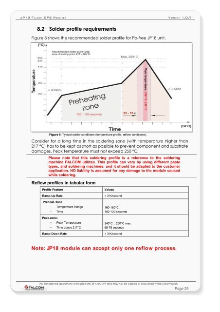
8.2 Solder profile requirements<br />
Figure 8 shows the recommended solder profile for Pb-free <strong>JP18</strong> unit.<br />
Figure 8: Typical solder conditions (temperature profile, reflow conditions).<br />
Consider for a long time in the soldering zone (with temperature higher than<br />
217 °C) has to be kept as short as possible to prevent component and substrate<br />
damages. Peak temperature must not exceed 250 °C.<br />
Please note that this soldering profile is a reference to the soldering<br />
machine <strong>FALCOM</strong> utilizes. This profile can vary by using different paste<br />
types, and soldering machines, and it should be adapted to the customer<br />
application. NO liability is assumed for any damage to the module caused<br />
while soldering.<br />
Reflow profiles in tabular form<br />
Profile Feature Values<br />
Ramp-Up Rate < 3 K/second<br />
Preheat- zone<br />
– Temperature Range<br />
– Time<br />
Peak-zone:<br />
– Peak Temperature<br />
– Time above 217°C<br />
160-180°C<br />
100-120 seconds<br />
240°C .. 250°C max.<br />
65-75 seconds<br />
Ramp-Down Rate < 3 K/second<br />
Note: <strong>JP18</strong> module can accept only one reflow process.<br />
This confidential document is the property of <strong>FALCOM</strong> and may not be copied or circulated without permission.<br />
Page 29