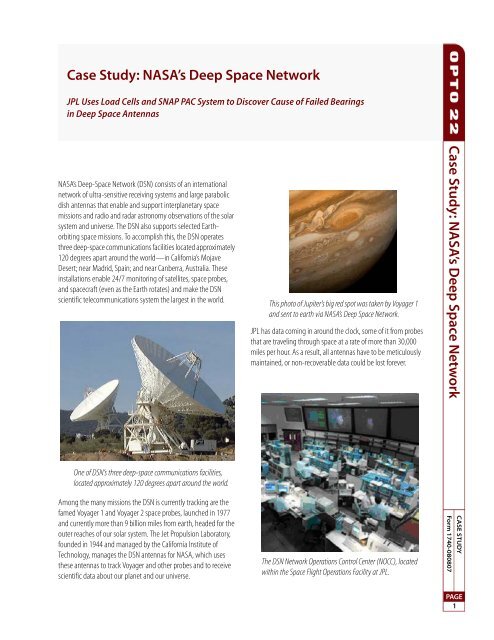
Case Study: NASA's Deep Space Network C ase Study ... - Opto 22
Case Study: NASA's Deep Space Network C ase Study ... - Opto 22
Case Study: NASA's Deep Space Network C ase Study ... - Opto 22

You also want an ePaper? Increase the reach of your titles
YUMPU automatically turns print PDFs into web optimized ePapers that Google loves.
<strong>C<strong>ase</strong></strong> <strong>Study</strong>: NASA’s <strong>Deep</strong> <strong>Space</strong> <strong>Network</strong><br />
JPL Uses Load Cells and SNAP PAC System to Discover Cause of Failed Bearings<br />
in <strong>Deep</strong> <strong>Space</strong> Antennas<br />
NASA’s <strong>Deep</strong>-<strong>Space</strong> <strong>Network</strong> (DSN) consists of an international<br />
network of ultra-sensitive receiving systems and large parabolic<br />
dish antennas that enable and support interplanetary space<br />
missions and radio and radar astronomy observations of the solar<br />
system and universe. The DSN also supports selected Earthorbiting<br />
space missions. To accomplish this, the DSN operates<br />
three deep-space communications facilities located approximately<br />
120 degrees apart around the world—in California’s Mojave<br />
Desert; near Madrid, Spain; and near Canberra, Australia. These<br />
installations enable 24/7 monitoring of satellites, space probes,<br />
and spacecraft (even as the Earth rotates) and make the DSN<br />
scientific telecommunications system the largest in the world.<br />
This photo of Jupiter’s big red spot was taken by Voyager 1<br />
and sent to earth via NASA’s <strong>Deep</strong> <strong>Space</strong> <strong>Network</strong>.<br />
JPL has data coming in around the clock, some of it from probes<br />
that are traveling through space at a rate of more than 30,000<br />
miles per hour. As a result, all antennas have to be meticulously<br />
maintained, or non-recoverable data could be lost forever.<br />
<strong>C<strong>ase</strong></strong> <strong>Study</strong>: NASA’s <strong>Deep</strong> <strong>Space</strong> <strong>Network</strong><br />
One of DSN’s three deep-space communications facilities,<br />
located approximately 120 degrees apart around the world.<br />
Among the many missions the DSN is currently tracking are the<br />
famed Voyager 1 and Voyager 2 space probes, launched in 1977<br />
and currently more than 9 billion miles from earth, headed for the<br />
outer reaches of our solar system. The Jet Propulsion Laboratory,<br />
founded in 1944 and managed by the California Institute of<br />
Technology, manages the DSN antennas for NASA, which uses<br />
these antennas to track Voyager and other probes and to receive<br />
scientific data about our planet and our universe.<br />
The DSN <strong>Network</strong> Operations Control Center (NOCC), located<br />
within the <strong>Space</strong> Flight Operations Facility at JPL.<br />
Form 1740-080807<br />
CASE STUDY<br />
PAGE<br />
1
<strong>C<strong>ase</strong></strong> <strong>Study</strong>: NASA’s <strong>Deep</strong> <strong>Space</strong> <strong>Network</strong><br />
In Madrid, an antenna similar to this one will be equipped with load cell transducers and the<br />
SNAP PAC System to discover why cracks have developed in the large elevation bearing system.<br />
Last summer at the DSN site in Madrid, during a time when a 230-foot<br />
antenna was already out of service for scheduled maintenance and<br />
upgrades, engineers detected cracks in the antenna’s large elevation<br />
bearing system. These bearings support the 4-million-pound weight<br />
of the antenna as it rotates and tilts up and down. The cracks were<br />
detected in two pairs of elevation bearings in June 2006, and the<br />
antenna’s return to service was extended from four to seven months so<br />
repairs could be made.<br />
Having one of the large antennas out of commission created a real but<br />
manageable problem. As a remedy, smaller antennas were arrayed<br />
together to support the higher data rate capabilities of a 70-meter<br />
antenna. Alternatively, spacecraft data rates were lowered so that<br />
these missions could be supported by a 34-meter antenna.<br />
Soon, however, JPL realized they were facing an even more serious<br />
problem. The cracking of the bearings in Madrid marked the second<br />
time this had occurred in approximately 16 years. Scientists and<br />
engineers determined there must be something unusual causing<br />
these premature failures.<br />
To determine the precise nature of the problem, the Madrid 230-foot<br />
antenna’s bearings will be lifted and the existing shim 1 pack removed<br />
and replaced with load cell transducers—devices that convert and<br />
express light, sound, pressure and other non-electrical forces as an<br />
electrical signal. The electrical signal output (normally in the order of a<br />
few millivolts) will then be plugged into an algorithm to calculate the<br />
force applied.<br />
In the c<strong>ase</strong> of the DSN’s Madrid 230-foot antenna, force will be<br />
measured to effectively weigh the antenna as it moves across the<br />
bearings. To accomplish this, JPL entered into a contract with Force<br />
Switch, Corp. of San Dimas, California (http://www.forceswitch.com/)<br />
to design and build custom 5/8” thick plates (each with 35 load cells)<br />
that will fit perfectly underneath the antenna without disturbing the<br />
alignment or compromising its ability to move in any way. In addition<br />
to this size specification, Force Switch (specialists in force-activated,<br />
weight-activated, and liquid level measurement solutions) will have to<br />
meet JPL’s other requirements for the load cells—chief among these<br />
is signal conditioning.<br />
These specially designed load cell plates will output milliamp signals<br />
rather than the typical millivolt type, which is very important because<br />
the load cells will be interfacing with an <strong>Opto</strong> <strong>22</strong> SNAP PAC System.<br />
1. A shim is a thin and often tapered or wedged piece of material, used to fill<br />
small gaps or spaces between objects. Shims are typically used in order to support,<br />
adjust for better fit, or provide a level surface. They may also be used as<br />
spacers to fill gaps between parts subject to wear.<br />
PAGE<br />
2
<strong>C<strong>ase</strong></strong> <strong>Study</strong>: NASA’s <strong>Deep</strong> <strong>Space</strong> <strong>Network</strong><br />
Specifically, SNAP analog input modules will connect the four<br />
individual plates (one for each set of bearings) to SNAP-PAC-EB2<br />
processors (or “brains”), which will receive accurate load cell<br />
readings—expressed as analog current inputs in the –20 mA to<br />
+20 mA range—once every second.<br />
Rele<strong>ase</strong>d this spring, the EB2 is one of the newest additions to<br />
<strong>Opto</strong> <strong>22</strong>’s SNAP PAC family of products for automation, monitoring,<br />
and data acquisition.<br />
“The SNAP-PAC-EB2 processor has dual, switched 10/100 Mbps<br />
Ethernet interfaces, which is perfect for multi-drop architectures like<br />
the one JPL requires,” explains Tom Edwards, Senior Technical Advisor<br />
at <strong>Opto</strong> <strong>22</strong>.<br />
Edwards (and other engineers at <strong>Opto</strong> <strong>22</strong>) provided pre-sales support<br />
for JPL and helped define the requirements for the <strong>Deep</strong> <strong>Space</strong><br />
<strong>Network</strong> antenna project. Together, they determined that the project is<br />
going to require long cable runs (approximately 300 feet) with<br />
distributed I/O at the four load cell/bearing locations. Edwards says<br />
that the SNAP-PAC-EB2 brain is going to give JPL the ability to “daisychain”<br />
1 distributed I/O and bring all of the load cell readings<br />
aggregated by the EB2s back to one intelligent controller, likely<br />
<strong>Opto</strong> <strong>22</strong>’s SNAP-PAC-R2 programmable automation controller. From<br />
there, data will be sent to a JPL datab<strong>ase</strong> via <strong>Opto</strong>DataLink, which<br />
provides multiple connections for exchanging data between the SNAP<br />
PAC System and SQL datab<strong>ase</strong>s.<br />
Currently, JPL is working with <strong>Opto</strong> <strong>22</strong> to design the system to read the<br />
140 analog signals at 1 Hz (once per second) and as close to<br />
synchronously as possible. Eventually, the frequency could be<br />
incre<strong>ase</strong>d to 4 Hz or possibly more.<br />
With the SNAP PAC System continuously monitoring and recording<br />
load cell data from multiple locations as the antenna moves over the<br />
bearings, JPL will soon be studying the data, formulating theories, and<br />
determining why the bearings have been cracking.<br />
1. In electrical and electronic engineering, a daisy chain is a wiring scheme in<br />
which, for example, Device A is wired to Device B, Device B is wired to Device C,<br />
Device C is wired to device D, and so on. Daisy chains may be used for power,<br />
analog signals, digital data, or a combination thereof.<br />
PAGE<br />
3
<strong>C<strong>ase</strong></strong> <strong>Study</strong>: NASA’s <strong>Deep</strong> <strong>Space</strong> <strong>Network</strong><br />
About <strong>Opto</strong> <strong>22</strong><br />
<strong>Opto</strong> <strong>22</strong> develops and manufactures hardware and software for<br />
applications involving industrial automation and control, remote<br />
monitoring, and data acquisition. <strong>Opto</strong> <strong>22</strong> products use standard,<br />
commercially available networking and computer technologies, and<br />
have an established reputation worldwide for simplicity, innovation,<br />
quality, and reliability. <strong>Opto</strong> <strong>22</strong> products are used by automation endusers,<br />
OEMs, and information technology and operations personnel.<br />
The company was founded in 1974 and is privately held in Temecula,<br />
California, USA. <strong>Opto</strong> <strong>22</strong> products are available through a worldwide<br />
network of distributors and system integrators. For more information,<br />
contact <strong>Opto</strong> <strong>22</strong> headquarters at 951-695-3000 or visit<br />
www.opto<strong>22</strong>.com.<br />
PAGE<br />
4<br />
Form 1740-080807 • <strong>Opto</strong> <strong>22</strong> • 43044 Business Park Drive • Temecula, CA 92590-3614 • www.opto<strong>22</strong>.com<br />
SALES 800-321-6786 • 951-695-3000 • FAX 951-695-3095 • sales@opto<strong>22</strong>.com • SUPPORT 800-835-6786 • 951-695-3080 • FAX 951-695-3017 • support@opto<strong>22</strong>.com<br />
© 2008 <strong>Opto</strong> <strong>22</strong>. All rights reserved. Dimensions and specifications are subject to change. Brand or product names used herein are trademarks or registered trademarks of their respective companies or organizations.